WITH AN AUTOCAD DWG DRAWING
←
→
Page content transcription
If your browser does not render page correctly, please read the page content below
Technical Note
                                                                      Structural Concrete Software System

                                                                                            TN246_getting_started_dwg_14
                                                                                                                  052907

                                 GETTING STARTED IN BUILDER1
                                WITH AN AUTOCAD DWG DRAWING

 This Technical Note is intended for the first time users of ADAPT-Modeler or Floor Pro, who want to
 generate a three dimensional structural model, starting from an AutoCAD drawing. The Technical Note
 assumes that the user is not much familiar with AutoCAD. Also, no prior preparation for simplification in
 the creation of a structural model is assumed to have been made in the AutoCad drawing (dwg
 drawing). Following the format of a detailed tutorial, the Technical Note walks you - the user - step by
 step through the generation of a complete model and its validation.

 The Technical Note assumes that you have already reviewed the companion Technical Note2 Design
 Steps Using Builder Floor-Pro, where you find an overview of the modeling and design process along
 with the steps that you have to follow for a complete design, including the generation of structural
 drawings.

 The material presented is organized as follows:

           1 – ADAPT Builder User Interface
           2 – Import AutoCAD Drawing
           3 – Calibrate the Imported Drawing
           4 – Change of Origin
           5 – Automatic Generation of Polygons
           6 – Set Floor-to-Floor Heights
           7 – Transformation of Graphical Entities to Structural Components
           8 – Creation of Structural Components
           9 – Establish Component Connectivity
           10 – Clear the Display From Non-related Entities
           11 – Validate the Structural Model

 1 – ADAPT Builder USER INTERFACE

 ADAPT-Modeler is the program module of the BUILDER platform that you use to generate the
 structural model, be it for analysis and design using finite elements (FLOOR-Pro), or strip method
 (ADAPT-PT/RC). Figure 1-1 shows the screen of the Modeler, with several of the many toolbars
 available opened for display. A detailed description of the user interface is given in the Modeler’s User
 Manual.

 ADAPT-Modeler operates the same way as other Windows programs. Program tools are accessed
 from one of the toolbars provided by the program or through the menus provided in the menu bar at the
 top of the screen. Toolbars may be opened, closed, “docked” to the edge of the screen or dragged

 1
     Copyright ADAPT Corporation 2007
 2
     TN230 PT Design Steps Using Builder Floor Pro

                              www. adaptsoft.com E-Mail support@adaptsoft.com
1733 Woodside Road, Suite 220, Redwood City, California, 94061, USA, Tel: (650) 306-2400 Fax (650) 306 2401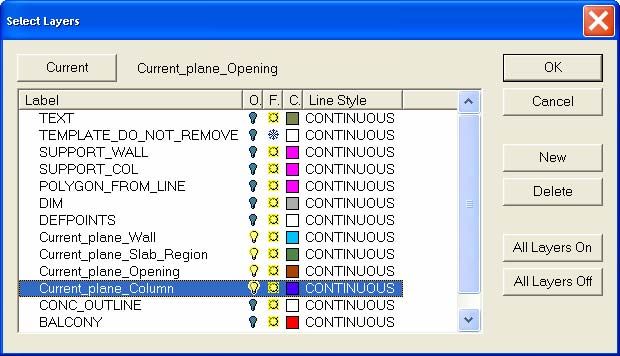
Technical Note
to any position on the screen as View menu item. Tools can also be accessed by clicking the right
mouse button while the cursor is in the Menu Bar or Toolbar areas of the screen.

                            FIGURE 1-1: ADAPT-MODELER USER INTERFACE

The User Information Bar at the bottom of the screen displays tool-specific information and the
information that users may be asked to enter for specific program procedures.

The Status Bar at the bottom, but last, displays information such as mouse cursor coordinates, current
system of units selected, snapping status, and gridline spacing and status. A short hint describing the
function of each tool displays, when the mouse cursor is placed over a tool.

Mouse Function and Operation
The primary function of the mouse is through its left-click. Depending on the mode of the program, as
outlined in the next section, the left-click will result in selecting the entity below the cursor, inserting an
entity or performing an operation at the location of the cursor. The right click of the mouse opens the
following dialog window listing the anticipated most common operations.

                                FIGURE 2-2: MOUSE RIGHT CLICK WINDOW

                                                       2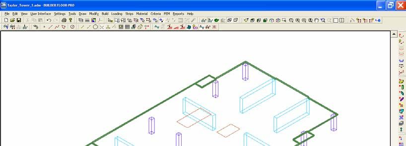
Technical Note
How to Abandon an Operation
To abandon an operation you have already started, such as drawing a polygon, press the Esc key.
How to Close an Operation
When you want to accept and close an operation, such as closing a polygon, or the outline of an
opening you have been drawing, press C or End key
Operation Modes of the Program
At any given instance in its operation, the program is in one of the following modes. You will find, it is
critical to know the program’s current mode and be able to change it from one to the other. The
program’s modes are best identified by the shape of the cursor. They important modes are:
Selection or Pick Mode .
o Left click to select an entity. When an entity is selected, its color changes
o Double left click to open the property window of an entity.
Creation Mode
o In this mode the program is ready to generate a component, such as a slab or rebar.
Press Esc to exit this mode.
Other Modes, such as
o The above and other similar modes are self-explanatory.
Selection Toolbar
Among other toolbars of the program, the Selection Toolbar contains several of the most common tools
you will be using. Hence, it is reproduced below with a short description of the critical tools for model
generation.
FIGURE 3-3: MOUSE RIGHT CLICK WINDOW
Hint Mode. When activated, the arrow displays the identification of the entities to which it
points. In this mode you cannot select an entity by clicking on it.
Window Selection. When this tool is highlighted, the Pick/Select mode is active. You can
select an entity by clicking on it, or a group of entities by opening a window around the items
while the left mouse key is held down. When in this mode, the cursor will be in the form of a
small square ( ). This is the program mode you will be operating in most of the time.
Double-clicking on an entity opens its properties dialog box.
Lasso Selection. This tool allows you to draw an arbitrary polygon around a series of entities.
When the lasso is closed, all entities located within or along the lasso perimeter are selected.
To use this tool, do the following:
3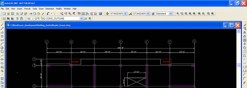
Technical Note

           o   Click on the Lasso Selection      tool.

           o   Draw segments of the polygon around the entities to be selected.

           o   Press C to close the lasso. The entities inside the lasso are selected automatically.

       Path Selection. With this tool you can select entities by drawing a polyline through them. To
       use this tool, do the following:

           o   Click on the Path Selection      tool.

           o   Draw polyline through the entities to be selected.

           o   Press C to end the line. The entities through which the line passes will be selected
               automatically.

       Select All. This tool selects all the entities visible on the screen.

       Move Selection. This tool enables you to move the entire group of entities that are currently
       selected. Pick a vertex of one of the entities in the selection and drag the entire group to the
       new location

       Move Selected Point. With this tool you can move only the vertex of an entity to a new
       location, while the positions of the remainder of the entity’s vertices remain unchanged.

       Item’s Properties. When you select an entity, followed by clicking on this tool, it opens the
       property window of the entity.

2– IMPORT AUTOCAD MODEL INTO BUILDER

In this section you will import an existing floor plan in AutoCAD dwg format to Modeler program. The
same procedure applies, when you import a drawing in DXF format. When imported, the entities such
as columns and walls will be shown by lines, polylines or polygons. In subsequent sections, you will
learn how to convert them to structural components. The plan view of the floor system you will work on
is shown below in a screen shot from AUTOCAD.

.

                                                         4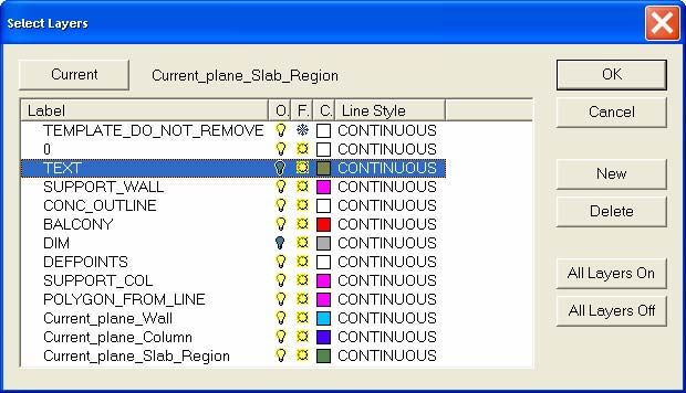
Technical Note
FIGURE 2-1: VIEW OF THE FLOOR PLAN IN AUTOCAD PROGRAM
Import the AutoCAD file into ADAPT Builder
Open Builder and ensure that in the first screen (splash window), you select American as
the system for units, if you wish to generate the model in American system of units.
Otherwise select SI.
In Builder, select File x Import xDWG/DXF. Browse for the AutoCAD file of this Technical
Note. It is called TN246_US.dwg. Select the file. After a short while the AutoCAD drawing
will appear on the Modeler screen.
If the drawing is not displayed, click on the “Zoom-Extents “ tool to have the imported
drawing enlarged and displayed centered on the screen.
3 – CALIBRATE THE IMPORTED FILE
Each time you import a drawing to Builder from AutoCAD you should specify one of its dimensions, in
order to scale the drawing to the correct size, before converting it to a structural model. In the normal
course of model generation, the program will guide you do so3. You will be asked to select two points in
the model and specify the distance between them. The program will scale the remainder of the file to
match the distance you have specified. It is advisable to select points that are far apart, and use
snapping tools. This increases the accuracy of the structural model you create.
3
If you miss this step, you can always you can activate the calibration tool by selecting the menu item “Calibrate
Drawing” from the “Tools” pull-down menu. Also, you can “scale” a structural model, once you have generated it.
5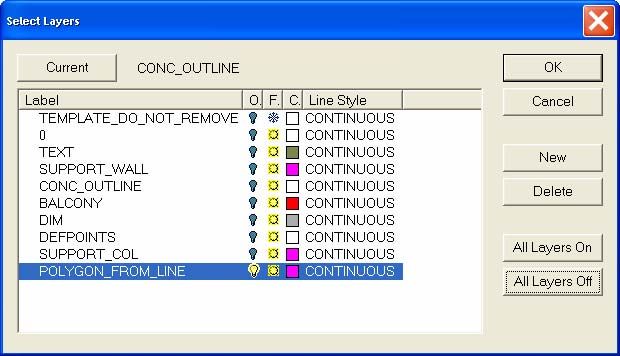
Technical Note
FIGURE 3-1 CALIBRATION DIALOG WINDOW
Calibrate the drawing as follows:
Answer Yes to the above dialog window4.
You will be asked at the bottom of the computer screen on the command line to enter the
information needed for calibration. Use the snap tool during calibration. Consider two points on
the plan, where you know the distance between them. Observe the length of the floor slab in
Fig. 3-2 (114 ft, 49m). This is a good dimension to select
FIGURE 3-2 PLAN CLOSE UP SHOWING LENGTH OF THE FLOOR
o With the snap to perpendicular on, click on the “start” point of the calibration line (Fig.
3-3a);
o next, click on the end point of the dimension line (Fig. 3-3b);
o observe the prompt at the bottom line of the computer screen and enter the distance
between the points (114 ft, 49m); and
o close by pressing Enter key.
The above re-sizes the drawing to the scale you have selected.
Center the model on the computer screen, by pressing the zoom extents tool.
4
Each time you import a drawing to Builder from AutoCAD you should specify one of its dimensions, in order to
scale the imported drawing to the correct size. You will be asked to do so by the program by selecting two points
in the model and specify the distance between them. It is advisable to select points that are far apart and
snapping tools to create an accurate model of the structure.
6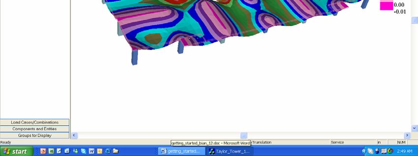
Technical Note

                                 (a) Arrow shows the start of dimension line

                               (b) Arrow shows the end of the dimension line

                             FIGURE 3 -3 SELECTION OF DIMENSION LINE

4 – CHANGE OF ORIGIN

Once you are done with the calibration of the model generated, a dialogue box will appear asking you
whether you want to change the origin of the global coordinates for the project. In most cases it is
acceptable to select No. In the case which you will be importing several DWG drawings into the same
model and have them automatically superimposed, you would select Yes5. In this case select No.

At this stage, the imported model will look as shown below.

                             FIGURE 4 – 1 VIEW OF IMPORTED MODEL

5
 If you plan to import several dwgs into one file and want them to be positioned exactly where you want them,
such as exactly over one another, you should change the origin of the coordinate system to a point chosen by
you. Say Yes and follow instructions. You can change the origin at a later stage if need be from Tools -> Change
Project Origin.
                                                       7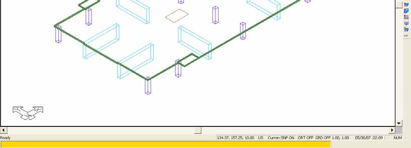
Technical Note
5 – AUTOMATIC CREATION OF POLYGONS
The boundary of slabs, walls, columns and openings are in form of polygons. It is possible that the dwg
you have imported does not delineate the outline of all of these entities by polygons. In many instances,
the Modeler can assist you to detect the boundary of the entities that are intended to represent
structural components, such as columns. This is the first step toward the transformation of graphical
entities of the drawing you have imported to structural components of Modeler. In this step, you will
use the program to convert to polygons as many of such occurrences as the program can detect.
In Builder, select Build x Display Modeling Toolbars, this will display all the toolbars you will be
using to convert the 2D entities into 3D structural components. Most of the operations will be
carried out using the tool bars in Fig. 5-1. One lists the tools that changes (transforms) a
drawing entity to a structural component. The other contains the tools for creating (building) new
structural components.
(a) Transformation Toolbar
(b) Creation Toolbar
FIGURE 5-1 STRCUTURAL COMPONENT GENERATION TOOLS
Click on “Transform Polygon “ Tool. The program prompts the followng, indicating
that it could locate 36 instances where connected lines could be converted to polygons
FIGURE 5 - 2
Next you will display the polygons generated in order to convert them to structural
components. To speed up the conversion, you will hide from display the items that are
not necessary and limit the display to the polygons for conversion to structural
components. From the Layers Setting tool open the layers dialog window.
Click on the button All Layers Off to turn off all the layers.
Locate the layer Polygons_From_Lines, as shown in Fig. 5-3. This will display the polygons
generated by the program (Fig. 5-4). Note that some of the polygons are readily identifiable as
intended to represent structural components, such as columns and walls. The polygons that
were in the original dwg imported, if any, will not be displayed on this view.
8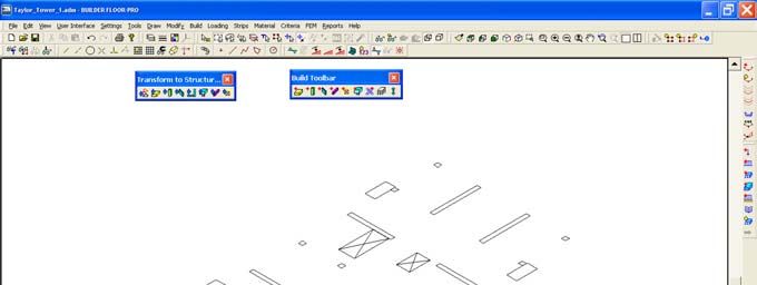
Technical Note
FIGURE 5-3
FIGURE 5-4 DISPLAY OF POLYGONS GENERATED BY THE PROGRAM
6 – SET FLOOR TO FLOOR HEIGHTS
The entities shown on the screen at this time are 2D. There is no height associated with them. You
need to define a default value for the length of these components, such as columns, above and below
the floor you are creating. This is done by you defining a floor-to-floor distance between the current
floor that you are modeling and the floors above and below. This will result in the columns and walls
you create to extend initially from the current level to the levels above and below. You can later change
the length of each of these components, you need be.
From creation toolbar click on Level Assignment Tool . The following window opens. Note
that the distance between the current plane and the one above and below it is given at 10 ft
(3m). Accept the values displayed and close the window. Obviously, you have the option to
change these, where the floor to floor heights are different.
9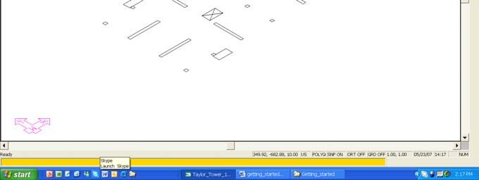
Technical Note
FIGURE 6-1 FLOOR-TO-FLOOR HEIGHT ASSIGNMENT DIALOG WINDOW
7 – TRANSFORMATION OF GRAPHICAL ENTITIEYS TO STRUCTURAL COMPONENTS
At this step, you will convert the polygons that represent structural components, such as columns, to
structural components. It is best to change the display to oblique view to better see the 3D components
that you transform. Do the following.
Click on the Top-front-right-view . The following appears.
FIGURE 7 – 1 OBLIQUE VIEW OF THE PLOYGONS GENERATED
Select a polygon that represents a wall, such as the one shown below.
10Technical Note
FIGURE 7 – 2 SELECTION OF A POLYGON THAT
REPRESENTS A WALL
Click on the Transform Wall tool to create a wall at this location, with a cross-sectional
area defined by this polygon and a height defined by the floor to floor height tool you used
above. The following shows the view of the wall created.
FIGURE 7– 4 VIEW OF WALL TRANSOFRMED FROM A
POLYGON
Check the properties of this wall by double clicking the left mouse on it. The property window of
the wall opens (shown below). Examine the values of the property assigned to the wall. In this
Technical Note tutorial, we are not going to change the wall properties, such as it material and
height.
11Technical Note
FIGURE 7-5 PROPERTY WINDOW OF WALL
Close the property box by clicking on the top right cross on it. However, if you change any of the
wall’s properties, you need to click on the confirmation tool to validate your change.
Similar to the transformation of the wall above, select the polygon at the bottom left of the
display and transform it to a column as shown below.
FIGURE 7 – 6 DISPLAY OF A TRANSFORMED COLUMN
Transform the rest of the walls by selecting the rest of the polygons that represent walls as
detailed below:
o Keep the control key depressed, while you click on the entity that you wish to add to the
selection.
o If you make a mistake and select an entity that you did not intend to be part of the list,
keep the control button depressed and click one more time on the item that you want to
de-select.
12Technical Note
(a) Display of polygons intended to be columns
(b) Display of converted columns
FIGURE 7 – 7 TRANSFORMATION OF WALLS
Next select the polygons that are intended to be transformed to columns. Again, keep the
control key depressed for adding to the selection. If you make the wrong selection, click on the
entity one more time to deselect it. When all the column polygons are selected, the screen looks
as shown below.
13Technical Note
(a) Display of polygons representing columns
(b) Display of columns and walls transformed from polygons
FIGURE 7 – 8 TRANSOFRMED COLUMNS AND WALLS
The four rectangular polygons on the boundary of the image are each a balcony. Select the one
at the bottom left and change it to a slab region using the Transform to Slab Tool .”
14Technical Note
FIGURE 7-9 CONVERSION OF ONE POLYGONE TO BALCONY SLAB REGION
The balconies are 7” (180 mm) thick and are 1” (25mm) lower than the floor slab at the interior
of the building. Next we define the thickness of this balcony and its drop with respect to the rest
of the floor system. Once you define the properties of one entity, such as the balcony slab in
this case, the subsequent entities that you transform will assume the same property.6 Double
click on the transformed balcony to open its property window (shown below).
FIGURE 7-10 PROPERTY WINDOW OF BALCONES
6
If the next entity you transform or create does not assume the properties of the last entity of the same kind you
transformed, do the following starting from Settings pull-down menu Settings -> General Settings and check
mark the item “Use the properties of the last modified component of the same type as default.”
15Technical Note
In the property window of the slab region opened, change the slab thickness to 7” (180mm).
Click on the “Location” tab, and change the “Vertical offset” to 1”. This will bring the balcony 1”
(25mm) below the reference plane (floor slab level at the interior of the building). Later, we will
generate the main floor on the reference plane.
FIGURE 7 – 11 PROPERTY WINDOW OF BALCONY SLAB
Select the remainder three polygons that represent balconies and convert them to balconies as
shown below.
FIGURE 7 – 12 CONVERSION OF REMAINDER OF BALCONIES
Open the property box of one of the balconies converted above and verify that its slab thickness
is 7” and it is offset by 1” (25mm). If this is not the case, make the necessary correction in the
property window of the balcony opened and confirm your entry by clicking on .
16Technical Note
There are three openings in this floor system. Click on one of the polygons that represents an
opening for its transformation. You will note, as shown in the figure below, that the selected
polygon is a triangle. The program did not recognize the boundary of the opening as the
polygon that represents the outline of the opening. Leave for now the conversion of these
polygons to openings. At a later stage, you will create them using the creation tool.
FIGURE 7-13 CONVERSION OF POLYGON TO OPENING
By now, you have handled all the polygons that were created through the Transform Polygon
tool. The dwg file imported may have included polygons that are not displayed on this
view. If any, you will convert those polygons, when other layers are turned on.
View the components created so far for the visual confirmation of the validity of the work done.
Click on the View Model tool to obtain a 3D solid display of the components generated.
Rotate the assembly of the components and visually confirm their validity (Figure below).
FIGURE 7-14 3D VIEW OF STRUCTURAL COMPONENTS
17Technical Note
8 – CREATION OF STRCTURAL COMPONENTS
To create the remainder of the structural components from AutoCad drawing, you have to trace each.
You will find, the tools that are available for you to make the tracing and conversion are fast and simple.
The best is to start by going through the layers that were imported from AutoCAD, and select only those
layers for view that include the components you plan to create. This may not be practical in all cases,
since some layers may have more than what is required, or may not have all that you need, as is the
case in the dwg we have imported. Do the following
Exit the 3D solid viewer
Display the model on plan view
Open the Select layers dialog window (shown below).
FIGURE 8 – 1 SELECT LAYERS DIALOG WINDOW
Turn all layers on. Turn “DIM” and “TEXT” layers off. Click on OK to go back to the model. The
plan shown below appears.
FIGURE 8 – 2 PARTIAL VIEW OF THE FLOOR SYSTEM
18Technical Note
You will use the tools listed below to trace the lines define the boundaries of slabs and
openings:
o Snap tools, in particular snap to intersection, snap to end, snap to nearest
o Insert point
o Move point
o Delete point
In navigating over the drawing to “pan” and “zoom” you can use the mouse middle button
as follows:
o Roll the middle button to “zoom “in and out; and
o keep the middle button depressed and move the mouse to “pan.”
You will now create the main slab of the floor system by tracing its outline on the dwg
drawing. Click on the create slab tool from the Build Toolbar below:
Turn all the snap tools off from the toolbar below:
FIGURE 8-3 SNAP TOOLBAR
Click on the snap to intersection “ to turn it on.
Starting from one corner of the slab outline, such as top left, bring the cursor close to the
slab corner and left click, when the snap sign “yellow X” shows up (Fig. below).
FIGURE 8-4 SNAP TO INTERSECTION AT THE CORNER
OF SLAB OUTLINE
Continue tracing the outline of the slab from vertex to vertex, each time click the left mouse
when the cursor snaps to an intersection point. In the course of your tracing, it is likely that you
would miss a point, or click at the wrong position, or have to quit the tracing prematurely. This is
not critical to your work, since you will subsequently correct the mistakes through the editing
19Technical Note
tools. As an example, the figure shown below illustrates a partially completed slab outline with
several of the points not correctly snapped at the slab outline. In addition, the slab outline drawn
does not cover the entire slab.
FIGURE 8-5 INCOMPLETE CREATION OF SLAB BOUNDARY
To correct a point that is not snapped correctly on the slab outline, such as the two points
shown in the figure above, do the following.
Zoom in on the location
Select the slab you have created (figure below)
FIGURE 8-6 INCOMPLETE SLAB BOUNDARY SELECTED FOR EDITING
20Technical Note
Make sure that the cursor is in pick mode (indicated by a small square)
The vertices of the slab you have created so far are revealed with small squares. Bring
the cursor over one such vertex that needs correction, pick it (left mouse), move it close
to the correct location until the snapping sign shows, left click the mouse to lock the slab
vertex at the correct position.
FIGURE 8-7 VERTEX OF A SLAB BOUNDARY BEING SNAPPED
TO COORECT LOCATION
FIGURE 8-8 VERTEX OF A SLAB BOUNDARY SNAPPED
TO COORECT LOCATION
In the course of completing and editing the outline of the slab, in addition to insert point
you are likely to use the undo tool, if a point you have created is at the wrong
21Technical Note
location; use delete point , add point, and move selected point . Continue with the
tracing of the slab outline, until complete as shown below.
FIGURE 8-9 VIEW OF COMPLETED SLAB BOUNDARY
View the structure in 3D viewer to visually confirm the work you have done so far. The
3D model should look as shown below.
FIGURE 8-10 VIEW OF COMPLETED SLAB BOUNDARY
Next create the openings by clicking on the create opening tool, while the snap to
intersection tool is on. Trace the outline of each opening. When complete, the structure
will look as shown below:
22Technical Note
FIGURE 8-11 VIEW OF COMPLETED STRUCTURE
Check the slab thickness and its elevation by opening the slab’s property box (double
click on its boundary). You will note its slab thickness is 7” (180mm) which is the default
you had for the balcony. Change the slab thickness to 8” (200mm). Next from the
location tab, change the vertical offset to 0 in, This will establish the position of the slab
1” (25mm) above that of the balcony. Click on tool to validate your correction. Close
the slab’s property box.
9 – ESTABLISH COMPONENT CONNECTIVITY
The structural model you have created is complete and ready to be validated. However, the solution
you will obtain will be more accurate, if the top of the walls and columns are shifted below the slab, as
opposed to have them extended to the top of the slab in the model’s current condition. To adjust the
connectivity of the columns and walls to the slab, do the following:
From Build pull down menu ->Preprocessing -> Establish Component Connectivity.
View the model and verify that the columns and walls terminate at the soffit of the slab.
10 – CLEAR THE DISPLAY FROM NON-RELATED ENTITIES
At this stage, it is a good idea to clear from the display of the structural model from the unnecessary
lines, text and information, before proceeding to the validation of the model you have generated. Each
of the structural components you have generated is placed in its own layer. The layers generated by
the program for your current model are:
Current_plane_column
Current_plane_opening
Current_plane_slab_region
Current_plane_wall
Do the following:
Open the layer dialog window (shown below)
Click on the Label tab to organize the list of layers alphabetically
23Technical Note
Turn all layers off
Turn on only the component layers listed above
Press OK
FIGURE 10 – 1 SELECT LAYER DIALOG WINDOW
The model you have created should look like the image below
FIGURE 10 – 2 COMPLETE PLAN OF THE STRUCTURAL MODEL
11 – VALIDATE THE STRUCTURAL MODEL
This stage of the work is applicable if you plan to use FLOOR-Pro program for a finite element analysis
and design of the structure. If you plan to use the model to generate data for ADAPT-PT or ADAPT-RC,
the following is not applicable to your work. For export to ADAPT-PT/RC the validation is achieved by a
close visual examination of the model generated.
For analysis and design using FLOOR-PRO, before moving ahead with the rest of data input, such as
definition of material properties, loads and more, it is important to validate your work. The validation is
done by obtaining a solution for selfweight of the structure using the default values of the program and
visually examining the deflected shape of the floor system. A close scrutiny of deflected shape of a floor
system under selfweight, can reveal many errors in model generation.
24Technical Note
From FEM pull down menu, click on automatic mesh generation. Accept the default settings
of the program. Press OK to close the window (shown below)
FIGURE 11-1 FINITE ELEMNET MESH GENERATION DIALOG WINDOW
Accept all the prompts of the program and respond by OK, continue, and affirmative as the
case may be. The mesh generated by the program is likely to be similar to the one shown
below:
FIGURE 11-2 FINITE ELEMNET MESH OF THE STRUCTURAL MODEL
Save the solution when prompted by the computer.
UP TO HERE ………….
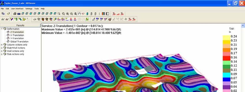
From FEM pull down menu, select view analysis results. Once in solution viewer, select
serviceability load case, deformation in Z-direction, and click on the tool to see the
deflection,
25Technical Note
Examine the deflected shape for the validity of the solution.
26You can also read