FLUXUS G722ST-LT Technical specification - FLEXIM

Page created by Sally Hart
 
CONTINUE READING
FLUXUS G722ST-LT Technical specification - FLEXIM
Technical specification

                                                                                       FLUXUS G722ST-LT

Steam ultrasonic flowmeter for permanent installation
Transmitter for permanent outdoor wall or pipe mounting

Features
• Exact and highly reliable measurement of saturated and su-
  perheated steam for temperatures up to max. 356 °F by
  means of the clamp-on principle
• Synchronized channel averaging to reduce turbulence-
  related fluctuations of the measured value
• Physical quantities volumetric flow rate and mass flow rate
  available in a transmitter without additional steam calculator
• Installation and start-up do not require any pipe work and are
  carried out without any process interruptions and cooling
  down of the steam system
• Non-invasive, wear-free and pressure constant measure-
  ment
• Maintenance-free acoustic coupling using permanent cou-
  pling foil
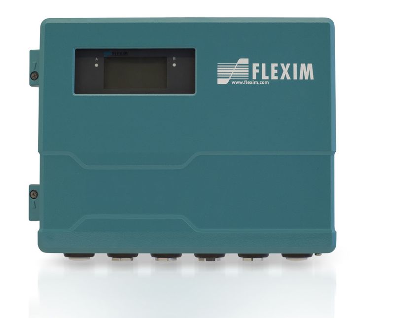
• High measurement accuracy even at very low as well and            FLUXUS G722ST-LT (aluminum housing)

  high flow rates and independent of the flow direction (bidirec-
  tional)
• Automatic loading of calibration data and transducer recogni-
  tion
• Bidirectional communication and support of common bus
  technologies (Modbus, Profibus PA, Foundation Fieldbus,
  BACnet)
• Advanced self-diagnosis and possibilities for event-based
  triggering of data recording for the supervision and control of
  critical processes
• Transmitter and transducers for use in hazardous areas are
  available
• Transmitter and transducers are separately calibrated (trace-
  able to national standards)
• The measurement is zero point stable and drift free
                                                                    FLUXUS G722ST-LT (stainless steel housing)

Applications
• Food and beverage industry
• Pharmaceutical industry
• Chemical industry
• Manufacturing industries

                                                                    PermaRail

TSFLUXUS_G722ST-LTV2-7US_Lus, 2021-07-01
FLUXUS G722ST-LT Technical specification - FLEXIM
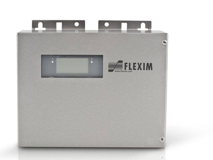
FLUXUS G722ST-LT                                                                                                                                              Technical specification

Function . . . . . . . . . . . . . . . . . . . . . . . . . . . . . . . . . . . . . . . . . . . . . . . . . . . . . . . . . . . . . . . . . . . . . . . . . . . . . . . . . . . . . . . 3
Measurement principle . . . . . . . . . . . . . . . . . . . . . . . . . . . . . . . . . . . . . . . . . . . . . . . . . . . . . . . . . . . . . . . . . . . . . . . . . . . . . 3
Calculation of volumetric flow rate . . . . . . . . . . . . . . . . . . . . . . . . . . . . . . . . . . . . . . . . . . . . . . . . . . . . . . . . . . . . . . . . . . . . 3
Calculation of mass flow rate . . . . . . . . . . . . . . . . . . . . . . . . . . . . . . . . . . . . . . . . . . . . . . . . . . . . . . . . . . . . . . . . . . . . . . . . 4
Number of sound paths . . . . . . . . . . . . . . . . . . . . . . . . . . . . . . . . . . . . . . . . . . . . . . . . . . . . . . . . . . . . . . . . . . . . . . . . . . . . 4
Typical measurement setup . . . . . . . . . . . . . . . . . . . . . . . . . . . . . . . . . . . . . . . . . . . . . . . . . . . . . . . . . . . . . . . . . . . . . . . . . 5

Transmitter . . . . . . . . . . . . . . . . . . . . . . . . . . . . . . . . . . . . . . . . . . . . . . . . . . . . . . . . . . . . . . . . . . . . . . . . . . . . . . . . . . . . . 6
Technical data . . . . . . . . . . . . . . . . . . . . . . . . . . . . . . . . . . . . . . . . . . . . . . . . . . . . . . . . . . . . . . . . . . . . . . . . . . . . . . . . . . . 6
Saturated steam pressure curve . . . . . . . . . . . . . . . . . . . . . . . . . . . . . . . . . . . . . . . . . . . . . . . . . . . . . . . . . . . . . . . . . . . . . 8
Dimensions. . . . . . . . . . . . . . . . . . . . . . . . . . . . . . . . . . . . . . . . . . . . . . . . . . . . . . . . . . . . . . . . . . . . . . . . . . . . . . . . . . . . . . 9
2" pipe mounting kit . . . . . . . . . . . . . . . . . . . . . . . . . . . . . . . . . . . . . . . . . . . . . . . . . . . . . . . . . . . . . . . . . . . . . . . . . . . . . . 10
Terminal assignment . . . . . . . . . . . . . . . . . . . . . . . . . . . . . . . . . . . . . . . . . . . . . . . . . . . . . . . . . . . . . . . . . . . . . . . . . . . . . 11

Transducers . . . . . . . . . . . . . . . . . . . . . . . . . . . . . . . . . . . . . . . . . . . . . . . . . . . . . . . . . . . . . . . . . . . . . . . . . . . . . . . . . . . 12
Transducer selection . . . . . . . . . . . . . . . . . . . . . . . . . . . . . . . . . . . . . . . . . . . . . . . . . . . . . . . . . . . . . . . . . . . . . . . . . . . . . 12
Technical data . . . . . . . . . . . . . . . . . . . . . . . . . . . . . . . . . . . . . . . . . . . . . . . . . . . . . . . . . . . . . . . . . . . . . . . . . . . . . . . . . . 13

Transducer mounting fixture. . . . . . . . . . . . . . . . . . . . . . . . . . . . . . . . . . . . . . . . . . . . . . . . . . . . . . . . . . . . . . . . . . . . . . 14

Coupling materials for transducers . . . . . . . . . . . . . . . . . . . . . . . . . . . . . . . . . . . . . . . . . . . . . . . . . . . . . . . . . . . . . . . . 16

Damping coat . . . . . . . . . . . . . . . . . . . . . . . . . . . . . . . . . . . . . . . . . . . . . . . . . . . . . . . . . . . . . . . . . . . . . . . . . . . . . . . . . . 17

Connection systems . . . . . . . . . . . . . . . . . . . . . . . . . . . . . . . . . . . . . . . . . . . . . . . . . . . . . . . . . . . . . . . . . . . . . . . . . . . . 18

Junction box . . . . . . . . . . . . . . . . . . . . . . . . . . . . . . . . . . . . . . . . . . . . . . . . . . . . . . . . . . . . . . . . . . . . . . . . . . . . . . . . . . . 19
Technical data . . . . . . . . . . . . . . . . . . . . . . . . . . . . . . . . . . . . . . . . . . . . . . . . . . . . . . . . . . . . . . . . . . . . . . . . . . . . . . . . . . 19
Dimensions. . . . . . . . . . . . . . . . . . . . . . . . . . . . . . . . . . . . . . . . . . . . . . . . . . . . . . . . . . . . . . . . . . . . . . . . . . . . . . . . . . . . . 19
2" pipe mounting kit . . . . . . . . . . . . . . . . . . . . . . . . . . . . . . . . . . . . . . . . . . . . . . . . . . . . . . . . . . . . . . . . . . . . . . . . . . . . . . 20

Clamp-on temperature probe (optional). . . . . . . . . . . . . . . . . . . . . . . . . . . . . . . . . . . . . . . . . . . . . . . . . . . . . . . . . . . . . 21
Technical data . . . . . . . . . . . . . . . . . . . . . . . . . . . . . . . . . . . . . . . . . . . . . . . . . . . . . . . . . . . . . . . . . . . . . . . . . . . . . . . . . . 21
Fixation. . . . . . . . . . . . . . . . . . . . . . . . . . . . . . . . . . . . . . . . . . . . . . . . . . . . . . . . . . . . . . . . . . . . . . . . . . . . . . . . . . . . . . . . 21
Junction box . . . . . . . . . . . . . . . . . . . . . . . . . . . . . . . . . . . . . . . . . . . . . . . . . . . . . . . . . . . . . . . . . . . . . . . . . . . . . . . . . . . . 21

2                                                                                                                            2021-07-01, TSFLUXUS_G722ST-LTV2-7US_Lus
Technical specification                                                                                      FLUXUS G722ST-LT

Function
Measurement principle
The transducers are mounted on the pipe which is completely filled with the fluid. The ultrasonic signals are emitted alter-
nately by a transducer and received by the other. The physical quantities are determined from the transit times of the ultra-
sonic signals.

 Path of the ultrasonic signal in the flowing fluid

As the fluid where the ultrasound propagates is flowing, the transit time of the ultrasonic signal in flow direction is shorter
than the one against the flow direction.
The transit time difference Δt is measured and allows the flowmeter to determine the average flow velocity along the prop-
agation path of the ultrasonic signals. A flow profile correction is then performed in order to obtain the area averaged flow
velocity, which is proportional to the volumetric flow rate.
The integrated microprocessors control the entire measuring cycle. The received ultrasonic signals are checked for mea-
surement usability and evaluated for their reliability. Noise signals are eliminated.

 Transit time difference Δt

                                                      t0             Δt

Calculation of volumetric flow rate
ꞏ                     t -
V = kRe · A · ka · ----------
                          2  t

where
ꞏ
V        -    volumetric flow rate
kRe      -    fluid mechanics calibration factor
A        -    cross-sectional pipe area
ka       -    acoustical calibration factor
Δt       -    transit time difference
tγ       -    average of transit times in the fluid

TSFLUXUS_G722ST-LTV2-7US_Lus, 2021-07-01                                                                                     3
FLUXUS G722ST-LT                                                                                                   Technical specification

Calculation of mass flow rate
The mass flow rate is calculated from the operating density and the volumetric flow rate:
mꞏ = ρ . Vꞏ
The operating density of the fluid is calculated as the function of pressure and temperature of the fluid:
ρ = f(p, T)
where
ρ        -    operating density
p        -    fluid pressure
T        -    fluid temperature
mꞏ       -    mass flow rate
 ꞏ
V        -    volumetric flow rate

Number of sound paths
The number of sound paths is the number of transits of the ultrasonic signal through the fluid in the pipe. Depending on the
number of sound paths, the following methods of installation exist:
• reflect arrangement
  The number of sound paths is even. The transducers are mounted on the same side of the pipe. Correct positioning of
  the transducers is easy.
• diagonal arrangement
  The number of sound paths is odd. The transducers are mounted on opposite sides of the pipe.
• direct mode
  Diagonal arrangement with 1 sound path. This should be used in the case of a high signal attenuation by the fluid, pipe
  or coatings.
The preferred method of installation depends on the application. While increasing the number of sound paths increases
the accuracy of the measurement, signal attenuation increases as well. The optimum number of sound paths for the pa-
rameters of the application will be determined automatically by the transmitter.
As the transducers can be mounted with the transducer mounting fixture in reflect arrangement or diagonal arrangement,
the number of sound paths can be adjusted optimally for the application.

 Reflect arrangement, number of sound paths: 2

                                   a

 Diagonal arrangement, number of sound paths: 3

                                       a

 Direct mode, number of sound paths: 1                         Direct mode, number of sound paths: 1, negative transducer distance

                                            a>0                                                            a
Technical specification                                                                          FLUXUS G722ST-LT

Typical measurement setup
 Example of a reflect arrangement

                                                            transmitter

                   external pressure sensor                               temperature probe

                                              transducers

                                                                                          pipe
                          damping coat                       insulation

TSFLUXUS_G722ST-LTV2-7US_Lus, 2021-07-01                                                                        5
FLUXUS G722ST-LT                                                                                                                       Technical specification

Transmitter
Technical data
                                FLUXUS                                          FLUXUS                             FLUXUS
                                G722ST-NN0*A                                    G722ST-A20*A                       G722ST-F20*A
                                G722ST-NN0*S                                    G722ST-A20*S                       G722ST-F20*S

design                          standard field device                           standard field device              standard field device
                                                                                zone 2                             FM Class I Div. 2
application                     steam measurement2
measurement
measurement                     transit time difference correlation principle
principle
synchronized                    x (2 measuring channels necessary)
channel averaging
flow velocity            ft/s depending on pipe diameter and transducer, see diagrams
repeatability                 0.15 % MV ±0.02 ft/s
fluid                         saturated steam, superheated steam
fluid pressure           psia 44 to 145
fluid temperature        °F 275 to 356                                275 to 311 (see pipe surface temperature 275 to 329
                                                                      (Ex) of selected transducer)
temperature com-              corresponding to the recommendations in ANSI/ASME MFC-5.1-2011
pensation
measurement uncertainty (volumetric flow rate)
measurement uncer-      ±0.3 % MV ±0.02 ft/s
tainty of the measu-    includes calibration certificate traceable to NIST
             1
ring system
measurement uncer-      ±1 to 3 % MV ±0.02 ft/s, depending on the application
tainty at the measu-
ring point
transmitter
power supply            • 100 to 230 V/50 to 60 Hz or
                        • 20 to 32 V DC or
                        • 11 to 16 V DC
power consumption W     < 15
number of measuring     1, optional: 2
channels
damping              s  0 to 100 (adjustable)
measuring cycle      Hz 100 to 1000 (1 channel)
response time        s  1 (1 channel), option: 0.02
housing material        aluminum, powder coated or stainless steel 316L
degree of protection    IP66                                                                                       aluminum housing: IP66/NEMA 4X
                                                                                                                   stainless steel housing: IP65
dimensions          inch see dimensional drawing
weight              lb   aluminum housing: 11.9
                         stainless steel housing: 11.2
fixation                 wall mounting, optional: 2" pipe mounting
ambient temperature °F -40 to +140                                                                                 aluminum housing: -40 to +131/140
                         (< -4 °F without operation of the display)                                                (< -4 °F without operation of the display)
                                                                                                                   stainless steel housing: -4 to +131/140
display                         128 x 64 pixels, backlight
menu language                   English, German, French, Spanish, Dutch, Russian, Polish, Turkish, Italian
explosion protection
• ATEX/IECEx
marking                         -                                                             II3G                 -
                                                                                    0637
                                                                                              II2D
                                                                                Ex nA nC ic IIC T4 Gc
                                                                                Ex tb IIIC T120 °C Db
                                                                                Ta -40...+60 °C
certification ATEX              -                                               IBExU11ATEX1015                    -
certification IECEx             -                                               IECEx IBE 11.0008                  -
• FM
marking                         -                                               -                                  G721**-F20*S2,
                                                                                                                   G721**-F20*S3:
                                                                                                                           NI/Cl. I,II,III/Div. 2/
                                                                                                                           GP. A,B,C,D,E,F,G/
                                                                                                                           T5

                                                                                                                   G721**-F20*S1:
                                                                                                                           NI/Cl. I,II,III/Div. 2/
                                                                                                                           GP. A,B,C,D,E,F,G/
                                                                                                                           T4A
1
    with aperture calibration of the transducers
2   test measurement to validate the application required in advance

6                                                                                                            2021-07-01, TSFLUXUS_G722ST-LTV2-7US_Lus
Technical specification                                                                                                                FLUXUS G722ST-LT

                              FLUXUS                                   FLUXUS                                     FLUXUS
                              G722ST-NN0*A                             G722ST-A20*A                               G722ST-F20*A
                              G722ST-NN0*S                             G722ST-A20*S                               G722ST-F20*S
measuring functions
physical quantities         operating volumetric flow rate, mass flow rate, flow velocity
totalizer                   volume, mass
calculation functions       average, difference, sum (2 measuring channels necessary)
diagnostic functions        sound speed, signal amplitude, SNR, SCNR, standard deviation of amplitudes and transit times
communication interfaces
service interfaces          measured value transmission, parametrization of the transmitter:
                            • USB
                            • LAN
process interfaces          max. 1 option:
                            • RS485 (ASCII sender)
                            • Modbus RTU
                            • BACnet MS/TP
                            • Profibus PA
                            • FF H1
                            • Modbus TCP
                            • BACnet IP
accessories
data transmission kit       USB cable
software                    • FluxDiagReader: reading of measured values and parameters, graphical presentation
                            • FluxDiag (optional): reading of measurement data, graphical presentation, report generation, parametrization of the transmitter
data logger
loggable values             all physical quantities, totalized physical quantities and diagnostic values
capacity                    max. 800 000 measured values
outputs
                            The outputs are galvanically isolated from the transmitter.
• switchable current output
                            All switchable current outputs are jointly switched to active or passive.
number                      2 (1 measuring channel), optional: 4 (2 measuring channels)
range                 mA 4 to 20 (3.2 to 22)
accuracy                    0.04 % MV ±3 μA
active output               Rext < 350 Ω
passive output              Uext = 8 to 30 V, depending on Rext (Rext < 1 kΩ at 30 V)
• digital output
functions                   • frequency output
                            • binary output
                            • pulse output
number                      3
operating parame-           5 to 30 V/< 100 mA
ters
frequency output
• range               kHz 0 to 5
binary output
• binary output as          limit, change of flow direction or error
  alarm output
pulse output
• functions                 mainly for totalizing
• pulse value         units 0.01 to 1000
• pulse width         ms 0.05 to 1000
inputs
                            The inputs are galvanically isolated from the transmitter.
• temperature input
number                      1 (1 measuring channel), optional: 2 (2 measuring channels)
type                        Pt100/Pt1000
connection                  4-wire
range                 °F -238 to +1040
resolution            K     0.01
accuracy                    ±0.01 % MV ±0.03 K
• current input
number                      1 (1 measuring channel), optional: 2 (2 measuring channels)
accuracy                    0.1 % MV ±10 μA
active input                Uint = 24 V, Rint = 50 Ω, Pint < 0.5 W, not short-circuit proof
• range               mA 0 to 20
passive input               Rint = 50 Ω, Pint < 0.3 W
• range               mA -20 to +20
1
    with aperture calibration of the transducers
2
    test measurement to validate the application required in advance

TSFLUXUS_G722ST-LTV2-7US_Lus, 2021-07-01                                                                                                                    7
FLUXUS G722ST-LT                                                                           Technical specification

Saturated steam pressure curve

                     T [°F]                application range
                       380
                       360
                       340
                       320
                       300
                       280
                       260
                       240
                       200                                        pabs [psi]
                           20    45   70   95      120         145

8                                                                     2021-07-01, TSFLUXUS_G722ST-LTV2-7US_Lus
Technical specification                                                                                              FLUXUS G722ST-LT

Dimensions
 *72***-****A

                                                          3.7

                                                                                                            .24 .2
                                                                                                         ø0 5 x 0
                                                                                         wall mount

                                                                                                          0.3

                                                                                                                             3.66
                                                                                                                                    6.52
                                                          10.04
                                                                               .2
                                                                      5   x0
                                 12.6                             0.3                                 7.49

                                           thread: 6x M20 x 1.5
 in inch                                   cable gland: max. 6x 1/2 NPT

 *72***-****S
                                                3.43

                                                        fixing holes for wall mounting
                          9.45
                                                         11.02
                                                10.04

                          12.6

                                            cable gland: max. 6x 1/2 NPS with counter nut
  in inch

TSFLUXUS_G722ST-LTV2-7US_Lus, 2021-07-01                                                                                                   9
FLUXUS G722ST-LT                            Technical specification

2" pipe mounting kit
*72***-****A
                               order code:
                               ACC-PE-*721-/PMK4

*72***-****S
                               order code:
                               ACC-PE-*721-/PMK6

10                     2021-07-01, TSFLUXUS_G722ST-LTV2-7US_Lus
Technical specification                                                                                                                                 FLUXUS G722ST-LT

Terminal assignment
    *72*

                                                                                                 LAN                           USB

                         AGN

                                             BGN
                         ARS

                                             BRS
                                             BVS
                         AVS

                                                                         T1A
                                                                         T1B

                                                                         T2A
                                                                         T2B
                                                                         T3A
                                                                         T3B

                                                                         T4A
                                                                         T4B

                                                                                                                P1+
                                                                                                                P2+
                                                                                                                P3+
                                                                                                                P4+
                                                                                                                P5a
                                                                                                                P6a
                                                                                                                P7a
                         AR

                                             BR
                                             BV

                                                                         S1

                                                                         S3
                         AV

                                                                                                                A+
                                                                                                                B-

                                                                                                                                                     L(+)
                                                                                                                                              N(-)
                                                                                                                                         PE
                        X_AV         X_AR   X_BV          X_BR
                                X2                   X3

                                                                                                                P5b
                                                                                                                P6b
                                                                                                                P7b
                                                                         T1a
                                                                         T1b

                                                                         T2a
                                                                         T2b
                                                                         T3a
                                                                         T3b

                                                                         T4a
                                                                         T4b

                                                                                                                P1-
                                                                                                                P2-
                                                                                                                P3-
                                                                                                                P4-
                                                                         S1

                                                                         S3

                                                                                                                S
                                                                                                                S
                                                                                                              *72***-****S                         *72***-****A
                                                                                                                       equipotential bonding terminal

power supply1
terminal                                                         connection (AC)                                    connection (DC)
PE                                                               earth                                              earth

N(-)                                                             neutral                                            -

L(+)                                                             phase                                              +

transducers

extension cable                                                                                              transducer cable
measuring channel A                             measuring channel B                                          measuring chan- measuring chan-
                                                                                                             nel A            nel B
terminal              connection                terminal                 connection        transducer        terminal                        connection
AV                    signal                    BV                       signal                              X_AV             X_BV           SMB connector

AVS                   shield                    BVS                      shield

ARS                   shield                    BRS                      shield                              X_AR                X_BR                       SMB connector

AR                    signal                    BR                       signal

outputs1
terminal                       connection                                                  terminal                 connection                  communication inter-
                                                                                                                                                face
P1+ to P4+                     current output                                              A+                       signal +                    • RS4851
P1- to P4-                                                                                                                                      • Modbus RTU1
                                                                                           B-                       signal -                    • BACnet MS/TP1
                                                                                                                                                • Profibus PA1
P5a to P7a                     digital output                                              101                      shield
P5b to P7b                                                                                                                                      • FF H11

                                                                                           USB                      type B                      • service (FluxDiag/
                                                                                                                    Hi-Speed USB 2.0              FluxDiagReader)
                                                                                                                    Device
                                                                                           LAN                      RJ45                        • service (FluxDiag/
                                                                                                                    10/100 Mbps Ethernet          FluxDiagReader)
                                                                                                                                                • BACnet IP
                                                                                                                                                • Modbus TCP
analog inputs1
                                temperature probe                                                       passive sensor                  active sensor
terminal                        direct connection                          connection with extension    connection                      connection
                                                                           cable
T1a to T2a                      red                                        white                        not connected                   not connected
T1A to T2A                      red                                        black                        -                               +
T1b to T2b                      white                                      red                          +                               not connected
T1B to T2B                      white                                      green                        not connected                   -
S1, S3                          shield                                     shield                       not connected                   not connected
1
    сable (by customer):
    - e.g., flexible wires, with insulated wire ferrules, wire cross-section: AWG14 to 24
    - outer diameter of the cable (*72***-****S with ferrite nut): max. 0.3 inch

TSFLUXUS_G722ST-LTV2-7US_Lus, 2021-07-01                                                                                                                                    11
FLUXUS G722ST-LT                                                                                                                         Technical specification

Transducers
Transducer selection
Step 1
pipe wall thickness
transducer order code

GLG                                                    0.4                                                 0.93

GLH                                      0.28                              0.62

GLK                        0.17                       0.37

GLM               0.08            0.19

GLP                      0.04 to 0.09

                                  0.2                0.4             0.6                   0.8                1                  1.2                   1.4
                                                                                                                                       pipe wall thickness [inch]

Step 2
inner pipe diameter d dependent on the flow velocity v of the fluid in the pipe

Direct mode, number of sound paths: 1                                             Reflect arrangement, number of sound paths: 2

     d [inch]                                                                      d [inch]
                                                               GLG                                                                        GLG
        40                                                                            40
        30                                                                            30
        20                                                                            20
        10                                                                            10
          0                                         v [Ō/s]                            0                                     v [Ō/s]
              0     40      80      120     160   200                                      0     40   80      120   160    200

     d [inch]                                                                      d [inch]
                                                               GLH                                                                        GLH
        40                                                                            40
        30                                                                            30
        20                                                                            20
        10                                                                            10
         0                                          v [Ō/s]                            0                                     v [Ō/s]
              0     40      80     120      160   200                                      0     40   80     120    160    200

     d [inch]                                                                      d [inch]
                                                               GLK                                                                        GLK
        16                                                                            16
        12                                                                            12
         8                                                                             8
         4                                                                             4
         0                                          v [Ō/s]                            0                                     v [Ō/s]
             0      40      80     120      160   200                                      0     40   80      120   160    200

     d [inch]                                                                      d [inch]
                                                               GLM                                                                        GLM
         8                                                                             8
         6                                                                             6
         4                                                                             4
         2                                                                             2
         0                                          v [Ō/s]                            0                                     v [Ō/s]
             0      40      80     120      160   200                                      0     40   80      120   160    200

     d [inch]                                                                      d [inch]                               GLP
                                                               GLP                                                                        GLP
         8                                                                             8
         6                                                                             6
         4                                                                             4
         2                                                                             2
         0                                          v [ft/s]                           0                                     v [Ō/s]
             0      40      80     120      160   200                                      0     40   80      120   160    200

inner pipe diameter and max. flow velocity for a steam application

12                                                                                                           2021-07-01, TSFLUXUS_G722ST-LTV2-7US_Lus
Technical specification                                                                                        FLUXUS G722ST-LT

Technical data
Lamb wave transducers (zone 2 - FM Class I Div. 2 - nonEx, steam measurement, TS)
order code                   GLG-S**TS/**      GLH-S**TS/**     GLK-S**TS/**     GLM-S**TS/**   GLP-SNNTS/**
technical type               G(RT)G1S52        G(RT)H1S52       G(RT)K1S52       G(RT)M1S52     G(RT)P1S52
transducer frequency MHz     0.2               0.3              0.5              1              2
fluid pressure               see saturated steam pressure curve
inner pipe diameter d
min.                  inch   8.9               5.9                3.5            1.8            0.91
max.                  inch   39.4              26.3               15.7           7.9            3.9
pipe wall thickness
min.                  inch   0.42              0.28               0.17           0.08           0.04
max.                  inch   0.93              0.62               0.37           0.19           0.09
material
housing                      PPSU with stainless steel cover 316Ti
contact surface              PPSU
degree of protection         IP65
transducer cable
type                         1699
length                ft     16                                                  13
length (***-*****/LC) ft     29                                                  29
dimensions
length l              inch   5.06                                                2.91
width b               inch   2.01                                                1.3
height h              inch   2.66                                                1.59
dimensional drawing
                                           h

                                                                                            h
                                    l                                                   l
                                           b

                                                                                            b
weight (without      lb    1.8                                                   0.35
cable)
storing temperature
min.                 °F -40
max.                 °F +356
operating temperature1
min.                 °F 212
max.                 °F 356
warm-up time         h     3                                                     1
temperature com-           x
pensation
explosion protection
• ATEX/IECEx
order code                 GLG-SA2TS/** GLH-SA2TS/**              GLK-SA2TS/**   GLM-SA2TS/**   -
pipe surface temperature (Ex)
• min.               °C -50                                                                     -
• max.               °C gas: +165, dust: +155                                                   -
marking
                               0637
                                          II3G                                                  -
                                          II2D
                           Ex nA IIC T6...T3 Gc
                           Ex tb IIIC T80 °C...T160 °C Db
certification ATEX         IBExU10ATEX1163 X                                                    -
certification IECEx        IECEx IBE 12.0005X                                                   -
• FM
order code                 GLG-SF2TS/**          GLH-SF2TS/**     GLK-SF2TS/**   GLM-SF2TS/**   -
pipe surface temperature (Ex)
• min.               °F -40                                                                     -
• max.               °F +329                                                                    -
degree of protection       IP66                                                                 -
marking                                NI/Cl. I,II,III/Div. 2 /                                 -
                                       GP A,B,C,D,E,F,G/
                                       Temp. Codes dwg 3860
completely thermically insulated transducer installation necessary

TSFLUXUS_G722ST-LTV2-7US_Lus, 2021-07-01                                                                                     13
FLUXUS G722ST-LT                                                                                                                                                Technical specification

Transducer mounting fixture
Order code

1, 2                  3                4             5          6          7 to 9                             no. of character
transducer mounting

                                                                           outer pipe diameter
                                       measurement
                                       arrangement

                                                                                                              description
                      transducer

                                                                fixation
fixture

                                                                                                     option
                                                     size

                                   -                        -                                    /
PL                                                                                                            PermaLok
VL                                                                                                            PermaRail
                      K                                                                                       transducers with transducer frequency G, H, K
                      M                                                                                       transducers with transducer frequency M, P
                                       D                                                                      reflect arrangement or diagonal arrangement/direct mode
                                       R                                                                      reflect arrangement
                                                     S                                                        small
                                                     L                                                        large
                                                                S                                             tension straps
                                                                           T36                                1.6 to 14.2 inch
                                                                           013                                0.39 to 5.1 inch
                                                                           036                                5.1 to 14.2 inch
                                                                           092                                14.2 to 36.2 inch
                                                                           200                                36.2 to 78.7 inch
                                                                           450                                78.7 to 177.2 inch
                                                                           SK1                                0.5 to 2.5 inch
                                                                           SK2                                3 to 6 inch
                                                                           SK3                                8 to 10 inch
                                                                           SK4                                12 to 18 inch
                                                                           SK5                                20 to 36 inch
                                                                           SK6                                42 to 100 inch
                                                                                                     OS       housing with stainless steel 316
                                                                                                     Z        special design

14                                                                                                                                    2021-07-01, TSFLUXUS_G722ST-LTV2-7US_Lus
Technical specification                                       FLUXUS G722ST-LT

 PermaRail (VLK, VLM)
                                           material: stainless steel 304, 301, 410
                                           option OS: 316Ti, 316L, 17-7PH
                                           inner length:
                                           VLK: 13.7 inch,
                                           VLM: 9.2 inch
                                           dimensions:
                                           VLK: 16.65 x 3.54 x 3.66 inch
                                           VLM: 12.17 x 2.24 x 2.48 inch

 PermaLok PL
                                           material: stainless steel 316
                                           dimensions:
                                           PLK-RL: 19.25 x 3.9 x 3.95 inch
                                           PLK-DS: 13.25 x 3.85 x 3.95 inch
                                           PLM: 25.25 x 3.08 x 3.15 inch
                                           PLQ: 13.37 x 2.68 x 2.4 inch
                                           weight:
                                           PLK-RL: 6 lb
                                           PLK-DS: 4.2 lb
                                           PLM: 6.6 lb
                                           PLQ: 2.8 lb

 quick release clasps and tension straps
                                           material: stainless steel 410, 200

TSFLUXUS_G722ST-LTV2-7US_Lus, 2021-07-01                                         15
FLUXUS G722ST-LT                                                             Technical specification

Coupling materials for transducers
type                              ambient temperature
                                  °F
coupling pad type VT1             14 to +392
coupling compound type E2         -22 to +392
1
    fluid temperature 392 °F: min. 2 years
2
    in combination with type VT only

16                                                      2021-07-01, TSFLUXUS_G722ST-LTV2-7US_Lus
Technical specification                                                                          FLUXUS G722ST-LT

Damping coat
The damping coat will be used to reduce acoustic noise influences on the measurement.

 Example (diagonal arrangement)

                                                                                        damping coat

                                                                                        transducer

Technical data
order code                  ACC-PE-GNNN-/DPL1
material                    multipolymeric matrix/inorganic ceramic coating
packing drum          gal   1
properties                  heat resistant, inert
fluid temperature     °F    50 to 392
when applying
drying time                 approx. 3 h at 68 °F
(example)                   approx. 15 min at 302 °F
temperature resis-    °F    max. 1202
tance in dry state
durability of the           2 years
packing drum
(unopened)
Observe installation instructions (TI_DampingCoat).

Dimensioning
transducer            number of packing drums
frequency
                      outer pipe diameter
                      ≤11.8                 ≤19.7                 ≤27.6
                      inch
G                     1                     1                     2
H                     1                     1                     1
K                     1                     1                     -
M                     1                     -                     -
P                     1                     -                     -

TSFLUXUS_G722ST-LTV2-7US_Lus, 2021-07-01                                                                       17
FLUXUS G722ST-LT                                                                                                                       Technical specification

Connection systems
connection system TS
connection with extension cable                                                               direct connection                         transducers
                                                                                                                                        technical type
                                                                                                                                        *****52
     JB02, JB03, JB04                                                                                                   x
                                                              x

                                                                                                transmitter
                                                                                transmitter
                                                          l

Cable
transducer cable
type                          1699
weight                  lb/ft 0.06
ambient temperature     °F -67 to +392
cable jacket
material                     PTFE
outer diameter          inch 0.11
thickness               inch 0.01
color                        brown
shield                       x
sheath
material                      stainless steel 316Ti

outer diameter          inch 0.31

extension cable
type                      2615                                    5245
weight              lb/ft 0.12                                    0.26
ambient temperature °F -22 to +158                                -22 to +158
properties                halogen free                            halogen free
                          fire propagation test according         fire propagation test according
                          to IEC 60332-1                          to IEC 60332-1
                          combustion test according to            combustion test according to
                          IEC 60754-2                             IEC 60754-2
cable jacket
material                  PUR                                     PUR
outer diameter      inch max. 0.47                                max. 0.47
thickness           inch 0.08                                     0.08
color                     black                                   black
shield                    x                                       x
sheath
material                  -                                       steel wire braid with copolymer
                                                                  sheath
outer diameter          inch -                                    max. 0.61

Cable length
transducer                    G, H, K                             M, P
frequency
transducers                   x                       l           x                                 l
technical type
*R***5*                 ft    16                      ≤ 984       13                                ≤ 984
option LC:              ft    29                      ≤ 984       29                                ≤ 984
*T***5*

x = transducer cable length
l = max. length of extension cable (depending on the application)

18                                                                                                                2021-07-01, TSFLUXUS_G722ST-LTV2-7US_Lus
Technical specification                                                                                                                  FLUXUS G722ST-LT

Junction box
Technical data
JB02, JB03, JB04
weight                lb   2.6 lb
                                                                Connection
fixation                   wall mounting
                           optional: 2" pipe mounting
material
housing                    stainless steel 316L
gasket                     silicone
degree of protection       IP67
ambient temperature
min.                 °F    -40
max.                 °F    +176
explosion protection
• ATEX
junction box               JB02
marking

                           II3G Ex nA IIC (T6)...T4 Gc
                           II3D Ex tc IIIC T 100 °C Dc
                           Ta -40...+(70)80 °C                  Transducers
• FM
junction box               JB04                                                         terminal               connection           transducer
marking                              NI/Cl. I,II,III/Div. 2 /                           XV                     SMB connector
                                     GP A,B,C,D,E,F,G/
                                     T6 Ta = -40...+60 °C                               XR                     SMB connector

                                                                Extension cable

                                                                terminal strip          terminal               connection
                                                                KL2                     TV                     signal
                                                                                        TVS                    internal shield
                                                                                        TRS                    internal shield
                                                                                        TR                     signal

Dimensions
 JB0*, JBP*

                                                                         wall mounting holder
                                                                                                   6.85
                                                        6.14

                                          Ø
                                              0.                                                          thread: 3x M20 x 1.5
                           2.76                    35             0.08
                                                                                                          cable gland: max. 2x 1/2 NPT
                           6.44                                                  4.69

 in inch

TSFLUXUS_G722ST-LTV2-7US_Lus, 2021-07-01                                                                                                               19
FLUXUS G722ST-LT                            Technical specification

2" pipe mounting kit
JB**
                               order code:
                               ACC-PE-GNNN-/JBPMK4

20                     2021-07-01, TSFLUXUS_G722ST-LTV2-7US_Lus
Technical specification                                                                                                          FLUXUS G722ST-LT

Clamp-on temperature probe (optional)
Technical data
PT13N
design                     clamp-on                             Connection system
type                       Pt1000
connection                 4-wire                               connection with extension cable                direct connection
measuring range       °F   -40 to +392
accuracy T                 ±(0.27 °F + 2 . 10-3 . (|T [°F]| -   extension cable
                           32 °F))
                           class A                                                   junction box
accuracy ΔT                ≤ 0.03 °F (at 50 °F)
(2x Pt matched                                                  Connection
according to
EN 1434-1)                                                                 temperature probe
housing                   360 brass alloy
                                                                           red
degree of protection      NEMA 4
dimensions                                                                 red
length l             inch 0.79
width b              inch 0.59                                             white
height h             inch 0.49
dimensional drawing                                                        white
                              b                      l
                                                                Cable
                                                           h

                                                                                          temperature probe         extension cable
weight               lb    0.437                                type                      4 x 24 AWG                4 x 18 AWG
accessories                                                     standard length      ft   20                        -
                                                                max. length          ft   -                         656
thermal conductivity       x
foil 482 °F                                                     cable jacket              PTFE                      LS PVC

Fixation
 tension strap PT13N

                                                                                                              material: stainless steel 301, 410
                                                                                                              thermal insulation necessary

Junction box

              1.18”                       4.72”                         1.18”         Connection

                                                                                      temperature probe        extension cable
                                                                                      red                      white
                                                                                      red                      black
                                                                                      white                    green
                                         Top View
                                                                                      white                    red
  ½” NPT

     1.34"

                                         Side View

TSFLUXUS_G722ST-LTV2-7US_Lus, 2021-07-01                                                                                                           21
FLEXIM AMERICAS Corporation
                            Edgewood, NY 11717
                                          USA
                                 Tel.:(631) 492-2300
                                 Fax:(631) 492-2117
                           internet: www.flexim.com
                          e-mail: usinfo@flexim.com
                                     1-888-852-7473
              Subject to change without prior notice.
                                   Errors excepted.
FLUXUS is a registered trademark of FLEXIM GmbH.
                  Copyright (©) FLEXIM GmbH 2021

  2021-07-01, TSFLUXUS_G722ST-LTV2-7US_Lus
You can also read