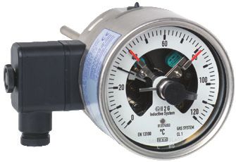
Gas-actuated thermometer with switch contacts Stainless steel version Model TGS73
←
→
Page content transcription
If your browser does not render page correctly, please read the page content below
Temperature

Gas-actuated thermometer with switch contacts
Stainless steel version
Model TGS73
                                                                                                      WIKA data sheet TV 27.01

                                                                 for further approvals
                                                                 see page 9

 Applications
■ Control and regulation of industrial processes
■ Monitoring of plants and switching of circuits
■ Universally suitable for machine building, plant, tank,
    equipment manufacturing and food industry
■ Temperature measurement without medium contact
■ Mounting in instrument boards, control cabinets, control
    panels

 Special features
■ Instruments meet the highest standards of measurement
    technology
■ Case and stem from stainless steel
■ For external mounting on pipes and tanks
■ Instruments with inductive contacts for use in hazardous
    areas
■ Instruments with contacts for PLC applications
                                                                 Fig. top: with capillary
                                                                 Fig. bottom: Back mount

Description

Wherever the process temperature has to be indicated             Switch contacts (electrical alarm contacts) make or break
on-site or in places that are difficult to access and, at the    circuits dependent upon the pointer position of the indicating
same time, circuits need to be switched, the gas-actuated        measuring instrument. The switch contacts are adjustable
thermometer with switch contacts finds its use.                  over the full measuring range. The instrument pointer (actual
                                                                 value pointer) moves freely across the entire scale range,
Due to the wide variety of possible designs, the                 independent of the setting. The set pointer can be adjusted
model TGS73 gas-actuated thermometers can be perfectly           via the window using a removable adjustment key (mounted
adapted to any process connection or location. With the          on the terminal box). Switch contacts consisting of several
adjustable stem and dial version, the case can be adjusted       contacts can also be set to a single set point. Contact
precisely to the desired viewing angle.                          actuation is made when the actual value pointer travels
With the contact bulb version (without direct contact with the   beyond or below the desired set point.
medium), the temperature can be measured and controlled
even when the pipe diameter is extremely small. The contact      As switch contacts, magnetic snap-action contacts, inductive
bulb is intended for external mounting on pipes and tanks.       contacts and electronic contacts are available. Inductive
When mounting this thermometer version, it must be ensured       contacts can be used in hazardous areas. For triggering
that the contact bulb is in contact with the measuring point     programmable logic controllers (PLC), electronic contacts
over its complete length.                                        can be used.

 WIKA data sheet TV 27.01 ∙ 03/2020                                                                               Page 1 of 18

Data sheets showing similar products and accessories:
Electrical switch contacts; model 8xx; see data sheet AC 08.01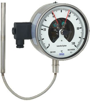
Specifications

 Gas-actuated thermometer, model TGS73
 Measuring element                                Gas-pressure inert gas filling, physiologically safe
 Nominal size in mm                               ■ 100
                                                  ■ 160

 Instrument version                               ■    Back mount (axial)
                                                  ■    Lower mount (radial)
                                                  ■    Back mount, adjustable stem and dial
                                                  ■    Version with capillary
 Connection designs                               ■ S, Standard (threaded connection) 1)
                                                  ■ 1, Plain stem (without thread)
                                                  ■ 2, Male nut
                                                  ■ 3, Union nut
                                                  ■ 4, Compression fitting (sliding on stem)
                                                  ■ 5, Union nut and loose threaded connection
                                                  ■ 6, Compression fitting (can be adjusted on either capillary or spiral protective sleeve)
                                                  ■ 7, Compression fitting at the case

 Unit (scale range)                               °C
                                                  Option:
                                                  ■ °F
                                                  ■ °C/°F (dual scale)

 Process connection                               ■  Plain, without thread
                                                  ■  G½B
                                                  ■  ½ NPT
                                                  ■  G ½ female
                                                  ■  ½ NPT female
                                                  ■  M20 x 1.5
                                                  ■  M24 x 1.5 female
                                                  others on request
 Accuracy class per DIN 16196                     Class 1
                                                  at 23 °C ±10 °C ambient temperature
 Rated operating ranges and conditions            DIN 16196 (EN 13190)
 Stem diameter                                    8 mm
                                                  Option:
                                                  ■ 6 mm
                                                  ■ 10 mm
                                                  ■ 12 mm
                                                  others on request
 Working range
      Continuous load (1 year)                    Measuring range (DIN 16196)
      Short time (max. 24 h)                      Scale range (DIN 16196)
 Window                                           Laminated safety glass
 Contact bulb                                     120 x 22 x 12 mm
 Adjustable stem and dial                         Swivelling 90°
                                                  360° rotatable
 Capillary                                        Ø 2 mm
                                                  Minimum curve radius: 6 mm
                                                  Length to customer specification
                                                  Option:
                                                  Armoured coating for capillary (Ø 7 mm spiral protective sleeve, flexible or PVC-
                                                  coated)
 Mounting types for instruments with capillary    ■ Surface mounting flange, stainless steel
                                                  ■ Instrument mounting bracket, aluminium die-casting
                                                  ■ Panel mounting flange, stainless steel

 Dampening (option)                               ■ With liquid dampening
                                                  ■ With food-compatible liquid dampening

1) Not applicable to instruments with capillary

 WIKA data sheet TV 27.01 ∙ 03/2020                                                                                            Page 2 of 18
Gas-actuated thermometer, model TGS73
Wetted materials
Stem, process connection Stainless steel 316SS
Non-wetted materials
Case, bayonet ring Stainless steel 304SS (option: stainless steel 316SS)
Contact bulb, capillary Stainless steel 316SS
Dial Aluminium, white, black lettering
Pointer Aluminium, black, adjustable pointer
Ingress protection per IEC/EN 60529 IP65
Option:
IP66
Permissible temperatures 2)
Ambient (at the case) -20 … +60 °C [-4 ... +140 °F] without/with liquid dampening
Storage and transport
Without liquid dampening -50 … +70 °C [-58 ... +158 °F]
With liquid dampening -40 … +70 °C [-40 ... +158 °F]
Permissible operating pressure at the stem max. 25 bar, static
Electrical connection Cable socket PA 6, black
According to VDE 0110 insulation group C/250 V
Cable gland M20 x 1.5
Strain relief
6 screw terminals + PE for conductor cross-section 2.5 mm²
Dimensions see page 12
others on request
2) For hazardous areas, the permissible temperatures of the contact model 831 shall apply exclusively (for permissible temperature ranges see page 5). These must not be exceeded at
the instrument either (for details see operating instructions). If necessary, measures for cooling (e.g. measuring point insulation) have to be taken.
WIKA data sheet TV 27.01 ∙ 03/2020 Page 3 of 18Scale range, measuring range, error limit (DIN 16196) Scale graduation per WIKA standard Scale range in °C Measuring range in °C 3) Scale spacing in °C Error limit in °C -80 ... +60 -60 ... +40 2 3.0 -60 ... +40 -50 ... +30 1 1.5 -40 ... +60 -30 ... +50 1 1.5 -30 ... +50 -20 ... +40 1 1.5 -20 ... +60 -10 ... +50 1 1.5 -20 ... +80 -10 ... +70 1 1.5 -20 ... +120 0 ... 100 2 3.0 -20 ... +140 0 ... 120 2 3.0 0 ... 60 10 ... 50 1 1.5 0 ... 80 10 ... 70 1 1.5 0 ... 100 10 ... 90 1 1.5 0 ... 120 10 ... 110 2 3.0 0 ... 160 20 ... 140 2 3.0 0 ... 200 20 ... 180 2 3.0 0 ... 250 30 ... 220 5 3.75 0 ... 300 30 ... 270 5 7.5 0 ... 400 50 ... 350 5 7.5 0 ... 500 50 ... 450 5 7.5 0 ... 600 100 ... 500 10 15.0 0 ... 700 100 ... 600 10 15.0 3) The measuring range is indicated on the dial by two triangular marks. Only within this range is the stated error limit valid per DIN 16196. Please indicate switch points! Unless otherwise specified, the instrument will be delivered with the adjustable switching points factory-set as follows: ■ Single contact Start of measuring range ■ Double contact Start and end of the measuring range WIKA data sheet TV 27.01 ∙ 03/2020 Page 4 of 18
Switch contacts                                                  Other versions
Magnetic snap-action contact model 821                           ■ Contact model 821 with separate circuits
■ No control unit and no power supply required                   ■ Contact model 821 as change-over contact (break or
■ Direct switching up to 250 V, 1 A                                make simultaneously at the set point)
■ Up to 4 switch contacts per measuring instrument               ■ Contact model 821 with cable break monitoring (parallel
                                                                   resistance 47 kΩ and 100 kΩ)
Inductive contact model 831                                      ■ Contact materials for contact model 821: Platinum-iridium
■ Suitable for use in hazardous areas with corresponding           alloy and gold-silver alloy
   control unit (model 904.xx)                                   ■ Contacts fixed, without contact adjustment lock
■ Long service life due to non-contact sensor                    ■ Contact adjustment lock leaded
■ Low influence on the indication accuracy                       ■ Contact adjustment key fixed
■ Fail-safe switching at high switching frequency                ■ Connector (instead of cable or cable socket)
■ Insensitive to corrosion
■ Also available in safety version
■ Up to 3 switch contacts per measuring instrument

Electronic contact model 830 E
■ For direct triggering of a programmable logic controller
   (PLC)
■ 2-wire system (option: 3-wire system)
■ Long service life due to non-contact sensor
■ Low influence on the indication accuracy
■ Fail-safe switching at high switching frequency
■ Insensitive to corrosion
■ Up to 3 switch contacts per measuring instrument

Switching function
The switching function of the switch is indicated by index 1,
2 or 3.
Model 8xx.1: Normally open (clockwise pointer motion)
Model 8xx.2: Normally closed (clockwise pointer motion)
Model 8xx.3: Change-over; one contact breaks and one
             contact makes simultaneously when pointer
             reaches set point

Please indicate switch points!
Unless otherwise specified, the instrument will be delivered
with the adjustable switching points factory-set as follows:
■ Single contact     Start of measuring range
■ Double contact Start and end of the measuring range
■ Triple contact     Start, middle and end of the measuring
                     range

Note
For magnetic snap-action contacts, it does not make sense
to test the display, around the set limit values, in the range
±5 % of the measuring span, because the magnet has an
influence on the indication accuracy.

For further information on switch contacts, see data sheet
AC 08.01

WIKA data sheet TV 27.01 ∙ 03/2020                                                                                Page 5 of 18
Specifications for instruments with magnetic snap-action contact model 821
The recommended setting range of the contacts is 25 ... 75 % of the scale (0 ... 100 % on request).
Contact material (standard): Silver-nickel, gold-plated
Setting of contacts to identical set point
The recommended minimum clearance between two contacts is 20 % of the scale range.
The switch hysteresis is 2 ... 5 % (typical).
Characteristics Unfilled instruments Filled instruments
Resistive load Resistive load
Switch version “L” Switch version “L”
Rated operating voltage Ueff ≤ 250 V ≤ 250 V
Rated operating current
Switch-on current ≤ 0.5 A ≤ 0.5 A
Switch-off current ≤ 0.5 A ≤ 0.5 A
Continuous current ≤ 0.3 A ≤ 0.3 A
Switching power ≤ 30 W / ≤ 50 VA ≤ 20 W / ≤ 20 VA
Recommended contact load with resistive and inductive loads
Operating voltage Unfilled instruments Filled instruments
Resistive load Inductive load Resistive load Inductive load
Direct Alternating cos ϕ > 0.7 Direct Alternating cos ϕ > 0.7
current current current current
DC 220 V / AC 230 V 100 mA 120 mA 65 mA 65 mA 90 mA 40 mA
DC 110 V / AC 110 V 200 mA 240 mA 130 mA 130 mA 180 mA 85 mA
DC 48 V / AC 48 V 300 mA 450 mA 200 mA 190 mA 330 mA 130 mA
DC 24 V / AC 24 400 mA 600 mA 250 mA 250 mA 450 mA 150 mA
WIKA data sheet TV 27.01 ∙ 03/2020 Page 6 of 18Specifications for instruments with inductive contact model 831 The recommended setting range of the contacts is 10 ... 90 % of the scale (0 ... 100 % on request). Setting of contacts to identical set point Up to 2 contacts can be set to an identical set point. For a version with 3 contacts this is not possible. The left (no. 1) or right (no. 3) contact may not be set to the same set point as the other 2 contacts. The required displacement is approx. 30°, optionally to the right or to the left. Available contact versions ■ 831-N ■ 831-SN, safety version 1) ■ 831-S1N, safety version 1), inverted signal 1) only operate with a corresponding isolating amplifier (model 904.3x) Permissible temperature range T6 T5 ... T1 T135°C -20 ... +60 °C -20 ... +70 °C -20 ... +70 °C For further information on hazardous areas, see operating instructions. Associated isolating amplifiers and control units Model Version Ex version 904.28 KFA6 - SR2 - Ex1.W 1 contact yes 904.29 KFA6 - SR2 - Ex2.W 2 contacts yes 904.30 KHA6 - SH - Ex1 1 contact yes - safety equipment 904.33 KFD2-SH-Ex1 1 contact yes - safety equipment 904.25 MSR 010-I 1 contact no 904.26 MSR 020-I 2 contacts no 904.27 MSR 011-I Two-point control no WIKA data sheet TV 27.01 ∙ 03/2020 Page 7 of 18
Specifications for instruments with electronic contact model 830 E

The recommended setting range of the contacts is 10 ... 90 % of the scale (0 ... 100 % on request).

Setting of contacts to identical set point
Up to 2 contacts can be set to an identical set point. For a version with 3 contacts this is not possible.
The left (no. 1) or right (no. 3) contact may not be set to the same set point as the other 2 contacts.
The required displacement is approx. 30°, optionally to the right or to the left.

 Characteristics
 Contact version                           Normally open, normally closed
 Type of output                            PNP transistor
 Operating voltage                         DC 10 ... 30 V
 Residual ripple                           max. 10 %
 No-load current                           ≤ 10 mA
 Switching current                         ≤ 100 mA
 Residual current                          ≤ 100 µA
 Voltage drop (with Imax.)                 ≤ 0.7 V
 Reverse polarity protection               Conditional UB (the switched output 3 or 4 must never be set directly to minus)
 Anti-inductive protection                 1 kV, 0.1 ms, 1 kΩ
 Oscillator frequency                      approx. 1,000 kHz
 EMC                                       per EN 60947-5-2

2-wire system (standard)                                              3-wire system

        Measuring instrument                   PLC                             Measuring instrument                       PLC
                                      4                                                                         2
                                                            +UB                                                                         +UB

                                      1                                                                         1
                                                            -                                                                           -

                     PNP                     RL (load)                                      PNP                 3

                                                                                                                       RL (load)

    With double contact                                                     With double contact

             2nd contact                                                             2nd contact

                                      2

                     PNP                   RL (2nd load)                                    PNP                 4

                                                                                                                      RL (2nd load)

WIKA data sheet TV 27.01 ∙ 03/2020                                                                                                 Page 8 of 18
Approvals
Logo Description Country
EU declaration of conformity European Union
■ EMC directive
■ Low voltage directive
■ RoHS directive
■ ATEX directive (option) 1)
Hazardous areas
- Ex ia Zone 1 gas [II 2G Ex ia IIC T6/T5/T4 * Gb]
Zone 21 dust [II 2D Ex ia IIIB T85°C/T95°C/T100°C/T135°C * Db]
IECEx (option) 1) International
Hazardous areas
- Ex ia Zone 1 gas [Ex ia IIC T6/T5/T4 * Gb]
Zone 21 dust [Ex ia IIIB T85°C/T95°C/T100°C/T135°C * Db]
EAC (option) Eurasian Economic Community
■ Import certificate
■ EMC directive
■ Hazardous areas 1)
GOST (option) Russia
Metrology, measurement technology
KazInMetr (option) Kazakhstan
Metrology, measurement technology
- MTSCHS (option) Kazakhstan
Permission for commissioning
BelGIM (option) Belarus
Metrology, measurement technology
Uzstandard (option) Uzbekistan
Metrology, measurement technology
- CRN (option) Canada
Safety (e.g. electr. safety, overpressure, ...)
1) Only for instruments with inductive contact model 831
Certificates (option)
■ 2.2 test report
■ 3.1 inspection certificate with 3 test points
(optionally with 5 test points)
■ DKD/DAkkS calibration certificate
Approvals and certificates, see website
WIKA data sheet TV 27.01 ∙ 03/2020 Page 9 of 18Connection designs
Standard design (male threaded connection) 1) Design 1, plain stem (without thread)
3073050.05
Standard insertion length l1 = 63, 100, 160, 200, 250 mm Standard insertion length l1 = 100, 140, 200, 240, 290 mm
Nominal Process Dimensions in mm Nominal size Dimensions in mm
size connection NS d1 2) Ød a for a for
NS G i SW d4 Ød axial adjustable stem and dial
100, 160 G½B 14 27 26 8 100, 160 18 8 15 25
G¾B 16 32 32 8 2) Not applicable to version with capillary
½ NPT 19 22 - 8
¾ NPT 20 30 - 8
1) Not applicable to instruments with capillary
Design 2, male nut Design 3, union nut
Standard insertion length l1 = 80, 140, 180, 230 mm Standard insertion length l1 = 89, 126, 186, 226, 276 mm
Nominal Process Dimensions in mm Nominal Process Dimensions in mm
size connection size connection
NS G i SW Ød NS G i SW Ød
100, 160 G½B 20 27 8 100, 160 G½B 8.5 27 8
M20 x 1.5 15 22 8 G¾B 10.5 32 8
M24 x 1.5 13.5 32 8
WIKA data sheet TV 27.01 ∙ 03/2020 Page 10 of 18Design 4, compression fitting (sliding on stem) Design 5, union nut and loose threaded connection
3073050.05
Sealing ring
Insertion length l1 = variable Standard insertion length l1 = 63, 100, 160, 200, 250 mm
Length L = l1 + 40 mm
Nominal Process Dimensions in mm
Nominal Process Dimensions in mm size connection
size connection NS G i SW d4 Ød
NS G i SW d4 Ød 100, 160 G½B 14 27 26 8
100, 160 G½B 14 27 26 8 G¾B 16 32 32 8
G¾B 16 32 32 8 M18 x 1.5 12 24 23 8
M18 x 1.5 12 24 23 8 ½ NPT 19 22 - 8
½ NPT 19 22 - 8 ¾ NPT 20 30 - 8
¾ NPT 20 30 - 8
Option: Connection with union nut M24 x 1.5
and loose threaded connection M18 x 1.5
Nominal size Process Dimensions in mm
connection
NS G i SW Ø d4 Ød
100, 160 M18 x 1.5 12 32 23 8
Design 6.1, compression fitting sliding on capillary Design 6.2, compression fitting sliding on capillary
(compression fitting is leak-proof) with spiral protective sleeve (compression fitting is
3073300.12
leak-proof)
Sealing ring Sealing ring
Insertion length l1 = variable Insertion length l1: ≥ 300 mm with Ø d = 6 or 8 mm
Probe length L: Standard 200 mm with Ø d = 6 mm ≥ 200 mm with Ø d = ≥ 10 mm
Standard 170 mm with Ø d = 8 mm Probe length L: Standard 200 mm with Ø d = 6 mm
Standard 100 mm with Ø d ≥ 10 mm Standard 170 mm with Ø d = 8 mm
Nominal Process Dimensions in mm Standard 100 mm with Ø d ≥ 10 mm
size connection Nominal Process Dimensions in mm
NS G i SW d4 Ød size connection
100, 160 G½B 14 27 26 8 NS G i SW d4 Ød
G¾B 16 32 32 8 100, 160 G½B 14 27 26 8
½ NPT 19 22 - 8 G¾B 16 32 32 8
¾ NPT 20 30 - 8 ½ NPT 19 22 - 8
¾ NPT 20 30 - 8
WIKA data sheet TV 27.01 ∙ 03/2020 Page 11 of 18Design 6.3, compression fitting sliding on spiral Design 7, compression fitting at the case
protective sleeve (compression fitting is not
14042662.02
leak-proof)
3073300.12
Sealing ring
Ferrule
Insertion length l1 = variable Insertion length l1: ≥ 400 mm
Probe length L: Standard 200 mm with Ø d = 6 mm Probe length L: Standard 200 mm with Ø d = 6 mm
Standard 170 mm with Ø d = 8 mm Standard 170 mm with Ø d = 8 mm
Standard 100 mm with Ø d ≥ 10 mm Standard 100 mm with Ø d ≥ 10 mm
IB = standard 100 mm (others on request)
Nominal Process Dimensions in mm
size connection Nominal Process Dimensions in mm
NS G i SW d4 Ød
size connection
100, 160 G½B 14 27 26 8 NS G i SW d4 Ød
G¾B 16 32 32 8 100, 160 G½B 14 27 26 8
½ NPT 19 22 - 8 G¾B 16 32 32 8
¾ NPT 20 30 - 8 ½ NPT 19 22 - 8
¾ NPT 20 30 - 8
Note for designs 6.1, 6.2, 6.3 and 7:
With some combinations, the active length l2 can correspond to the probe length L.
If an additional compression fitting is desired, the probe length L increases by at least 60 mm.
Legend:
G Male thread Ød Stem diameter
G1 Female thread l1 Insertion length
i Thread length (incl. collar) l2 Active length
a Distance to the case/articulated joint lF Capillary length
Ø d4 Diameter of the sealing collar lB Mounting shaft
SW Spanner width
Dimensions in mm
Cable socket
Contact model: 821 Contact models: 831 and 830 E
14062234.01
14336089.01
Only use cable with a Only use cable with a
diameter of 5 ... 10 mm diameter of 7 ... 13 mm
49.5
68
M20x1,5
M20x1,5
WIKA data sheet TV 27.01 ∙ 03/2020 Page 12 of 18Back mount
11442522.02
Lower mount Back mount
11442850.01
Adjustable stem and dial
11443171.01
Back mount, lower mount
Nominal Dimensions in mm Weight
size Switch contact model 821 or 831 in kg
1- or 2-way 3-way
NS b b1 1) b b1 1) d d4 D1 D2 F 1) G SW
100 88 121 - - 8 2) 26 101 99 83 G½B 27 1.3
160 88 121 96 129 8 2) 26 161 159 113 G½B 27 1.5
Back mount, adjustable stem and dial
Nominal Dimensions in mm Weight
size Switch contact model 821 or 831 in kg
1- or 2-way 3-way
NS b b1 b b1 d D1 D2 F
100 88 131 - - 8 2) 101 99 68 1.5
160 88 131 97 140 8 2) 161 159 68 1.7
1) With scale ranges ≥ 0 ... 300 °C the dimensions increase by 40 mm
2) Option: Stem diameter 6, 10, 12 mm
WIKA data sheet TV 27.01 ∙ 03/2020 Page 13 of 18Dimensions in mm for instruments with capillary
Surface mounting flange Instrument mounting bracket
11443872.01
1144674.01
Instruments NS 100 with panel mounting flange Instruments NS 160 with panel mounting flange
11444274.01
11444509.02
Nominal Dimensions in mm Weight
size Switch contact model 821 or 831 in kg
1- or 2-way 3-way
NS b b1 b b1 d d1 d2 d3 D1 D2 D3 h
100 88 91 - - 8 2) 116 132 4.8 101 99 107 107 1.6
160 88 91 97 100 8 2) 178 196 5.8 161 159 166 172 2,0
2) Option: Stem diameter 6, 10, 12 mm
WIKA data sheet TV 27.01 ∙ 03/2020 Page 14 of 18Dimensions in mm for instruments with contact bulb
Back mount
11443413.01
Lower mount Back mount, adjustable stem and dial
11443723.01
11443812.01
Connection Nominal Dimensions in mm Weight
location size Switch contact model 821 or 831 in kg
1- or 2-way 3-way
NS b b1 b b1 D1 D2
Back mount 100 88 - - - 101 99 1.0
160 88 - 97 - 161 159 1.1
Lower mount 100 88 - - - 101 99 1.0
160 88 - 97 - 161 159 1.1
Adjustable stem 100 88 131 - - 101 99 1.1
and dial
160 88 131 97 140 161 159 1.2
WIKA data sheet TV 27.01 ∙ 03/2020 Page 15 of 18Dimensions in mm for instruments with contact bulb and capillary
Surface mounting flange Instrument mounting bracket
11445092.01
11445165.01
Instruments NS 100 with panel mounting flange Instruments NS 160 with panel mounting flange
11445114.01
11445149.02
Nominal Dimensions in mm Weight
size Switch contact model 821 or 831 in kg
1- or 2-way 3-way
NS b b1 b b1 d1 d2 d3 D1 D2 D3 h
100 88 91 - - 116 132 4.8 101 99 107 107 1.6
160 88 91 97 100 178 196 5.8 161 159 166 172 2,0
WIKA data sheet TV 27.01 ∙ 03/2020 Page 16 of 18Mounting instructions for contact bulb
General information Capillary
The contact bulb has been designed for mounting on pipes
3107876.01
or tanks. When mounting this thermometer version, it must be Bend protection
ensured that the contact bulb is in contact with the measuring
point over its complete length. The basic requirements to
ensure a perfect measuring result is to retain good thermal
contact between the contact bulb and the outside wall of the
pipe or tank with minimal heat loss to the environment from
the contact bulb and measuring point.
■ Mounting on pipes ■ Mounting on tanks
The geometry of the contact bulb has been designed for The geometry of the contact bulb has been designed for
pipes with external diameters between 20 and 160 mm. For tanks with an external radius up to 80 mm. If the mounting
fixing the contact bulb to the pipe, pipe clamps are sufficient. point of the contact bulb on the tank has an external
The contact bulb should have direct metallic contact with the radius greater than 80 mm, we recommend the use of an
measuring point and have firm contact with the surface of intermediate piece designed for the respective tank diameter,
the pipe. Where temperatures under 200 °C are expected, a made of a material with good thermal conductivity. The
thermal compound can be used to optimise the heat transfer contact bulb can be fastened to the tank by means of an
between contact bulb and pipe. Insulation must be applied angle bracket with clamping screws, or any similar method.
at the mounting point to avoid error due to heat loss. This The contact bulb should have direct metallic contact with the
insulation must have sufficient temperature resistance and is measuring point and have firm contact with the surface of the
not included in the scope of delivery. tank.
Pipe clamp mounting A thermal compound can be used to optimise the heat
3107922.01
transfer between contact bulb and tank, if temperatures
Insulation
under 200 °C are expected. Insulation must be applied at the
mounting point to avoid error due to heat loss. This insulation
must have sufficient temperature resistance and is not
included in the scope of delivery.
Angle bracket mounting
3107930.01
Insulation
WIKA data sheet TV 27.01 ∙ 03/2020 Page 17 of 18Thermowell
In principle, the operation of a mechanical thermometer is
possible without a thermowell with low process-side loading
(low pressure, low viscosity and low flow velocities).
However, in order to enable exchanging the thermometer
during operation (e.g. instrument replacement or calibration)
and to ensure a better protection of the measuring instrument
and also the plant and the environment, it is advisable to use
a thermowell from the extensive WIKA thermowell portfolio.
For further information on the wake frequency calculation,
see Technical information IN 00.15.
Ordering information
Model / Nominal size / Type of contact and switching function / Scale range / Connection design / Process connection /
Length I1 / Capillary length IF / Options
© 06/2009 WIKA Alexander Wiegand SE & Co. KG, all rights reserved.
The specifications given in this document represent the state of engineering at the time of publishing.
We reserve the right to make modifications to the specifications and materials.
WIKA data sheet TV 27.01 ∙ 03/2020 Page 18 of 18
03/2020 DE
WIKA Alexander Wiegand SE & Co. KG
Alexander-Wiegand-Straße 30
63911 Klingenberg/Germany
Tel. +49 9372 132-0
Fax +49 9372 132-406
info@wika.de
www.wika.deYou can also read