AWR2243 Evaluation Module (AWR2243BOOST) mmWave Sensing Solution - User's Guide - Texas Instruments
←
→
Page content transcription
If your browser does not render page correctly, please read the page content below
AWR2243 Evaluation Module
(AWR2243BOOST) mmWave Sensing
Solution

User’s Guide

                     Literature Number: SPRUIT8D
               FEBRUARY 2020 – REVISED FEBRUARY 2021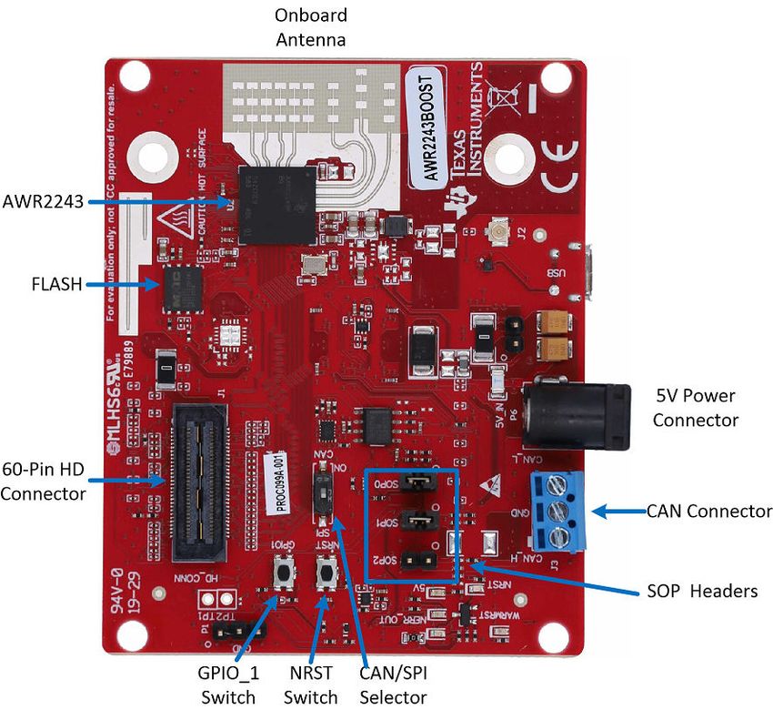
www.ti.com                                                                                                                                                            Table of Contents

                                                                                                                                            Table of Contents

1 Getting Started........................................................................................................................................................................7
  1.1 Introduction........................................................................................................................................................................ 7
  1.2 Key Features......................................................................................................................................................................7
  1.3 What is Included.................................................................................................................................................................7
2 Hardware................................................................................................................................................................................. 9
  2.1 Block Diagram..................................................................................................................................................................10
  2.2 Connecting BoosterPack™ to LaunchPad™ or MMWAVE-DEVPACK............................................................................ 11
  2.3 Power Connections.......................................................................................................................................................... 12
  2.4 Connectors.......................................................................................................................................................................12
  2.5 PC Connection................................................................................................................................................................. 16
  2.6 Antenna............................................................................................................................................................................17
  2.7 Jumpers, Switches, and LEDs......................................................................................................................................... 19
3 Design Files and Software Tools.........................................................................................................................................23
  3.1 LDO Bypass Requirement............................................................................................................................................... 23
4 Design Revision History...................................................................................................................................................... 25
5 Mechanical Mounting of PCB.............................................................................................................................................. 27
6 PCB Storage and Handling Recommendations.................................................................................................................29
7 Regulatory Information........................................................................................................................................................ 31
Revision History.......................................................................................................................................................................32

                                                                              List of Figures
Figure 2-1. EVM Front View.........................................................................................................................................................9
Figure 2-2. EVM Rear View....................................................................................................................................................... 10
Figure 2-3. BoosterPack™ Block Diagram................................................................................................................................ 10
Figure 2-4. 3V3 and 5-V Mark on the LaunchPad™ (White Triangle)....................................................................................... 11
Figure 2-5. Power Connector.....................................................................................................................................................12
Figure 2-6. 20-Pin BoosterPack™ Connectors (J5 and J6).......................................................................................................13
Figure 2-7. High Density Connector (60 Pin).............................................................................................................................15
Figure 2-8. XDS110 Ports.......................................................................................................................................................... 16
Figure 2-9. PCB Antenna...........................................................................................................................................................17
Figure 2-10. Antenna Pattern in H-Plane...................................................................................................................................18
Figure 2-11. Antenna Pattern in E-Plane................................................................................................................................... 18
Figure 2-12. SOP Jumpers........................................................................................................................................................ 19
Figure 2-13. Current Measurement Point.................................................................................................................................. 19
Figure 2-14. S1 Switch to Select Between SPI or CAN Interface..............................................................................................21
Figure 3-1. LDO Bypass Enable................................................................................................................................................ 24
Figure 5-1. Vertical Assembly of the EVM................................................................................................................................. 27

                                                                                List of Tables
Table 2-1. 20-Pin Connector Definition (J6)...............................................................................................................................14
Table 2-2. 20-Pin Connector Definition (J5)...............................................................................................................................14
Table 2-3. HD Connector Pin Definition..................................................................................................................................... 15
Table 2-4. SOP Modes...............................................................................................................................................................19
Table 2-5. Push Buttons.............................................................................................................................................................20
Table 2-6. LEDs......................................................................................................................................................................... 20
Table 4-1. Design Revision History............................................................................................................................................25

SPRUIT8D – FEBRUARY 2020 – REVISED FEBRUARY 2021                AWR2243 Evaluation Module (AWR2243BOOST) mmWave Sensing Solution                                                                3
Submit Document Feedback
                                           Copyright © 2021 Texas Instruments Incorporated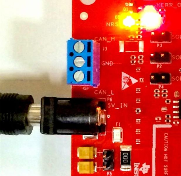
Table of Contents                                                                                                            www.ti.com

                                               This page intentionally left blank.

4     AWR2243 Evaluation Module (AWR2243BOOST) mmWave Sensing Solution                SPRUIT8D – FEBRUARY 2020 – REVISED FEBRUARY 2021
                                                                                                                 Submit Document Feedback
                                             Copyright © 2021 Texas Instruments Incorporated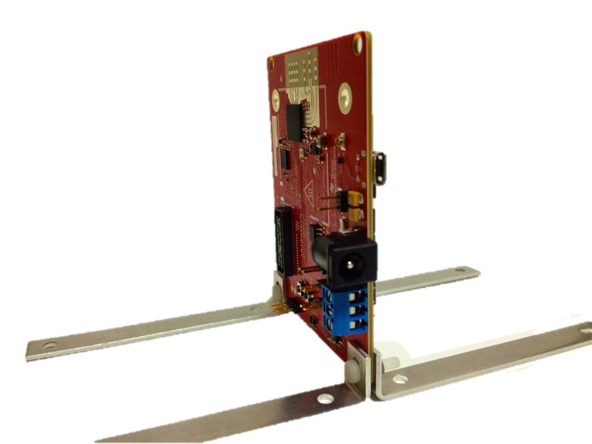
www.ti.com                                                                                                               Trademarks

Trademarks
BoosterPack™ and LaunchPad™ are trademarks of Texas Instruments.
Windows® is a registered trademark of Microsoft Corporation.
All trademarks are the property of their respective owners.

SPRUIT8D – FEBRUARY 2020 – REVISED FEBRUARY 2021                AWR2243 Evaluation Module (AWR2243BOOST) mmWave Sensing Solution      5
Submit Document Feedback
                                           Copyright © 2021 Texas Instruments Incorporated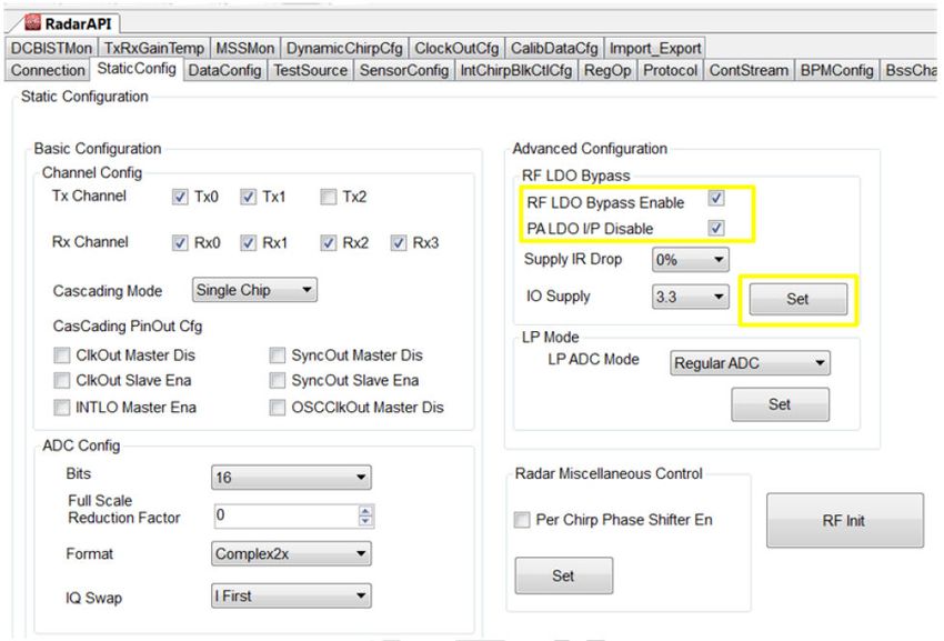
Trademarks                                                                                                                  www.ti.com

                                              This page intentionally left blank.

6    AWR2243 Evaluation Module (AWR2243BOOST) mmWave Sensing Solution                SPRUIT8D – FEBRUARY 2020 – REVISED FEBRUARY 2021
                                                                                                                Submit Document Feedback
                                            Copyright © 2021 Texas Instruments Incorporated
www.ti.com                                                                                                            Getting Started

                                                                                                                      Chapter 1
                                                                                                       Getting Started

1.1 Introduction
The AWR2243 BoosterPack™ is an evaluation board for the AWR2243 mmWave high-performance front end.
The evaluation platform enables raw capture of ADC data from the front end and evaluation of RF performance.
1.2 Key Features
•   40-pin LaunchPad™ standard that leverages the LaunchPad ecosystem
•   Backchannel UART through USB to PC, for logging purposes
•   Onboard antenna
•   60-pin high density (HD) connector, for raw ADC data over CSI, or the high-speed debug interface
•   One button and two LEDs, for user interaction
•   5-V power jack, to power the board
1.3 What is Included
1.3.1 Kit Contents
•   AWR2243BOOST
•   Mounting brackets, screws, and nuts, to allow placing the PCB vertical
•   Micro USB cable to connect to the PC

                                                               Note
      Not included: 5 V, >2.5-A supply brick with 2.1-mm barrel jack (center positive). TI recommends using
      an external power supply that complies with applicable regional safety standards such as UL, CSA,
      VDE, CCC, PSE, and so on. The cable length of the power cord must be < 3 m.

1.3.2 mmWave Proximity Demo
TI provides sample demo codes to easily get started with the AWR2243 evaluation module and experience the
functionality of the AWR2243 mmWave sensor. For details on getting started with these demos, see the
mmWave SDK User Guide.

SPRUIT8D – FEBRUARY 2020 – REVISED FEBRUARY 2021                AWR2243 Evaluation Module (AWR2243BOOST) mmWave Sensing Solution        7
Submit Document Feedback
                                           Copyright © 2021 Texas Instruments Incorporated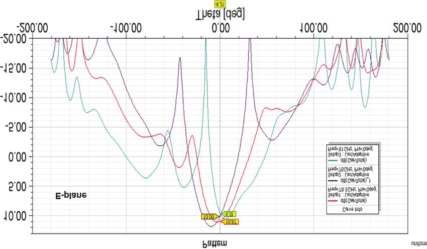
Getting Started                                                                                                               www.ti.com

                                                This page intentionally left blank.

8      AWR2243 Evaluation Module (AWR2243BOOST) mmWave Sensing Solution                SPRUIT8D – FEBRUARY 2020 – REVISED FEBRUARY 2021
                                                                                                                  Submit Document Feedback
                                              Copyright © 2021 Texas Instruments Incorporated
www.ti.com Hardware
Chapter 2
Hardware
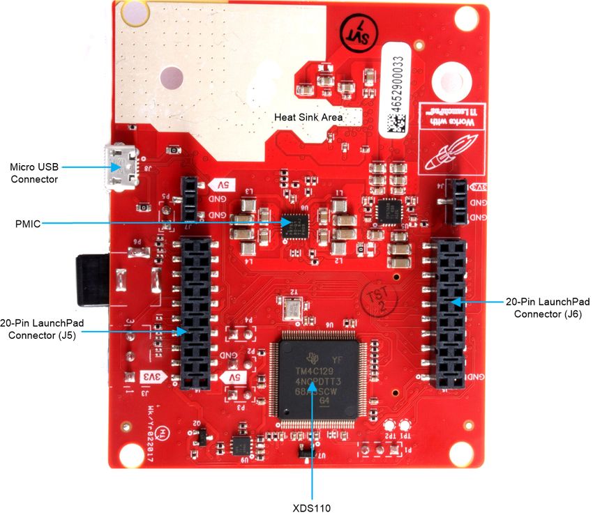
Figure 2-1 and Figure 2-2 show the front and rear views of the evaluation board, respectively.
Figure 2-1. EVM Front View
SPRUIT8D – FEBRUARY 2020 – REVISED FEBRUARY 2021 AWR2243 Evaluation Module (AWR2243BOOST) mmWave Sensing Solution 9
Submit Document Feedback
Copyright © 2021 Texas Instruments Incorporated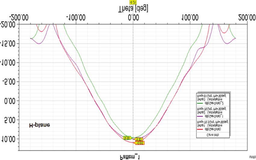
Hardware                                                                                                                    www.ti.com

                                                Figure 2-2. EVM Rear View

2.1 Block Diagram

                                       Figure 2-3. BoosterPack™ Block Diagram

10   AWR2243 Evaluation Module (AWR2243BOOST) mmWave Sensing Solution                SPRUIT8D – FEBRUARY 2020 – REVISED FEBRUARY 2021
                                                                                                                Submit Document Feedback
                                            Copyright © 2021 Texas Instruments Incorporated
www.ti.com Hardware
Note
The AWR2243 does not support CAN communication. Because the AWR2243BOOST shares the
same PCB as the AWR1443BOOST, the PCB contains a CAN connector (J3) and CAN PHY (U3);
however, the connector and PHY are not functional. The SPI/CAN selector switch (refer to Section
2.7.4 for more details) should always be set to ‘SPI’ mode on the AWR2243BOOST.
2.2 Connecting BoosterPack™ to LaunchPad™ or MMWAVE-DEVPACK
This BoosterPack can be stacked on top of the Launchpad, or the MMWAVE-DEVPACK, using the two 20-pin
connectors. The connectors do not have a key to prevent the misalignment of the pins or reverse connection.
Therefore, ensure reverse mounting does not take place. On the AWR2243 BoosterPack, we have provided 3V3
marking near pin 1 (see Figure 2-4). This same marking is provided on compatible LaunchPads which must
aligned before powering up the boards.
Figure 2-4. 3V3 and 5-V Mark on the LaunchPad™ (White Triangle)
SPRUIT8D – FEBRUARY 2020 – REVISED FEBRUARY 2021 AWR2243 Evaluation Module (AWR2243BOOST) mmWave Sensing Solution 11
Submit Document Feedback
Copyright © 2021 Texas Instruments IncorporatedHardware www.ti.com
2.3 Power Connections
The BoosterPack is powered by the 5-V power jack (>2.5-A current limit). As soon as the power is provided, the
NRST and 5-V LEDs glow, indicating that the board is powered up (see Figure 2-5).
Figure 2-5. Power Connector
Note
After the 5-V power supply is provided to the EVM, TI recommends pressing the NRST switch (SW2)
once to ensure a reliable boot up state.
2.4 Connectors
2.4.1 20-Pin BoosterPack™ Connectors
The BoosterPack has the standard LaunchPad connectors (J5 and J6) which enable the BoosterPack to be
directly connected to all TI MCU LaunchPads (see Table 2-1). While connecting the BoosterPack to other
LaunchPads, ensure the pin 1 orientation is correct by matching the 3V3 and 5-V signal marking on the boards
(see Figure 2-6).
12 AWR2243 Evaluation Module (AWR2243BOOST) mmWave Sensing Solution SPRUIT8D – FEBRUARY 2020 – REVISED FEBRUARY 2021
Submit Document Feedback
Copyright © 2021 Texas Instruments Incorporatedwww.ti.com Hardware
Figure 2-6. 20-Pin BoosterPack™ Connectors (J5 and J6)
SPRUIT8D – FEBRUARY 2020 – REVISED FEBRUARY 2021 AWR2243 Evaluation Module (AWR2243BOOST) mmWave Sensing Solution 13
Submit Document Feedback
Copyright © 2021 Texas Instruments IncorporatedHardware www.ti.com
Table 2-1 and Table 2-2 provide the connector-pin information.
Table 2-1. 20-Pin Connector Definition (J6)
Pin Number Description Pin Number Description
1 NERROUT 2 GND
3 NERRIN 4 NC
5 MCUCLK OUT 6 SPI_CS
7 NC 8 GPIO1
9 MSS LOGGER 10 nRESET
11 WARMRST 12 SPI_MOSI
13 BSS LOGGER 14 SPI_MISO
15 SOP2 16 HOSTINT
17 SOP1 18 GPIO2
19 SOP0 20 NC
Table 2-2. 20-Pin Connector Definition (J5)
Pin Number Description Pin Number Description
1 3V3 2 5V
3 NC 4 GND
5 RS232TX (Tx from IWR device) 6 ANA1
7 RS232RX (Rx into IWR device) 8 ANA2
9 SYNC_IN 10 ANA3
11 NC 12 ANA4
13 SPI_CLK 14 PGOOD (onboard VIO)
15 GPIO0 16 PMIC Enable
17 SCL 18 SYNC_OUT
19 SDA 20 PMIC CLK OUT
• PGOOD – This signal indicates the state of the onboard VIO supply for the AWR device coming from the
onboard PMIC. A high on the PGOOD signal (3.3 V) indicates that the supply is stable. Because the IOs are
not failsafe, the MCU must ensure that it does not drive any IO signals to the AWR device before this IO
supply is stable. Otherwise, there could be leakage current into the IOs.
• PMIC Enable – This signal goes onboard PMIC enable. The MCU can use this signal to completely shut
down the PMIC and AWR device to save power. The power up of the PMIC takes approximately 5 ms once
the Enable signal is released.
Note
To enable this feature, the R102 resister must be populated on the EVM.
14 AWR2243 Evaluation Module (AWR2243BOOST) mmWave Sensing Solution SPRUIT8D – FEBRUARY 2020 – REVISED FEBRUARY 2021
Submit Document Feedback
Copyright © 2021 Texas Instruments Incorporatedwww.ti.com Hardware
2.4.2 60-Pin High Density (HD) Connector
The 60-pin HD connector provides high speed data over CSI or the HS_DEBUG interface, and controls signals
(SPI, UART, I2C, NRST, NERR, and SOPs) and JTAG debug signals (see Table 2-3). This connector can be
connected to the MMWAVE-DEVPACK board and interface with the TSW1400 (see Figure 2-7).
Figure 2-7. High Density Connector (60 Pin)
Table 2-3. HD Connector Pin Definition
Pin Number Description Pin Number Description
1 5V 2 5V
3 5V 4 TDO
5 TDI 6 TCK
7 SPI_CS 8 TMS
9 SPI_CLK 10 HOSTINT
11 SPI_MOSI 12 SPI_MISO
13 PGOOD (onboard VIO) 14 NERROUT
15 NC 16 SYNC_IN
17 NC 18 GND
19 NC 20 DEBUG_VALIDP
21 NC 22 DEBUG_VALIDM
23 NC 24 GND
25 NC 26 DEBUG_FRCLKP
27 NC 28 DEBUG_FRCLKM
29 NC 30 GND
31 NC 32 DEBUG/CSI_3P
33 NC 34 DEBUG/CSI_3M
35 NC 36 GND
37 NC 38 DEBUG/CSI_2P
39 NC 40 DEBUG/CSI_2M
41 NC 42 GND
SPRUIT8D – FEBRUARY 2020 – REVISED FEBRUARY 2021 AWR2243 Evaluation Module (AWR2243BOOST) mmWave Sensing Solution 15
Submit Document Feedback
Copyright © 2021 Texas Instruments IncorporatedHardware www.ti.com
Table 2-3. HD Connector Pin Definition (continued)
Pin Number Description Pin Number Description
43 NC 44 DEBUG/CSI_CLKP
45 NC 46 DEBUG/CSI_CLKM
47 NC 48 GND
49 NC 50 DEBUG/CSI_1P
51 I2C_SDA 52 DEBUG/CSI_1M
53 I2C_SCL 54 GND
55 RS232RX (Rx into AWR device) 56 DEBUG/CSI_0P
57 RS232TX (Tx from AWR device) 58 DEBUG/CSI_0M
59 nRESET 60 GND
PGOOD – This signal indicates that the state of the onboard VIO supply for the AWR device coming from the
onboard PMIC. A high on the PGOOD signal (3.3 V) indicates the supply is stable. Because the I/Os are not
failsafe, the MCU must ensure that it does not drive any I/O signals to the AWR device before this I/O supply is
stable, to avoid leakage current into the I/Os.
2.5 PC Connection
Connectivity is provided using the micro USB connector over the onboard XDS110 (TM4C1294NCPDT)
emulator. This connection provides the following interfaces to the PC:
• JTAG for CCS connectivity
• UART1 for flashing the onboard serial flash, downloading FW using RADAR studio, and getting application
data sent over the UART
• MSS logger UART, which can be used to get MSS code logs on the PC
When the USB is connected to the PC the device manager recognizes the following COM ports, as shown in
Figure 2-8:
• XDS110 Class Application/User UART → the UART1 port
• XDS110 Class Auxiliary Data port → the MSS logger port
Figure 2-8. XDS110 Ports
If Windows® is unable to recognize the COM ports previously shown, install the emupack available here
2.5.1 Erasing Onboard Serial Flash
Before loading the code to the serial flash or connecting the board to RADAR Studio, TI recommends completely
erasing the onboard serial flash. The instructions to erase the onboard serial flash are in the mmWave SDK User
Guide.
16 AWR2243 Evaluation Module (AWR2243BOOST) mmWave Sensing Solution SPRUIT8D – FEBRUARY 2020 – REVISED FEBRUARY 2021
Submit Document Feedback
Copyright © 2021 Texas Instruments Incorporatedwww.ti.com Hardware
2.5.2 Connection With MMWAVE-DEVPACK
Mmwave SDK demos and released labs do not require the DevPack to be used with the BoosterPack. Users
may be required to use the DevPack along with the BoosterPack for the following use cases:
• Connecting to RADAR studio. This tool provides capability to configure the mmWave front end from the PC.
This tool is available in the DFP package.
• Capturing high-speed LVDS data using the TSW1400 platform from TI. This device allows the user to capture
raw ADC data over the high-speed debug interface and post process it in the PC. The RADAR Studio tool
provides an interface to the TSW1400 platform as well, so that the front end configurations and data capture
can be done using a single interface. Details on this board can be found at http://www.ti.com/tool/
tsw1400evm
For details on these use cases, see the mmWave-DevPack User Guide.
2.5.3 Connecting the BoosterPack to the DCA1000
The BoosterPack can be connected to the DCA1000 FPGA platform for LVDS streaming over Ethernet. For
detailed information on how to capture LVDS data using the DCA1000, see the following resources:
• DCA1000 Product Page
• DCA1000 User's Guide
• DCA1000 Training Video
2.6 Antenna
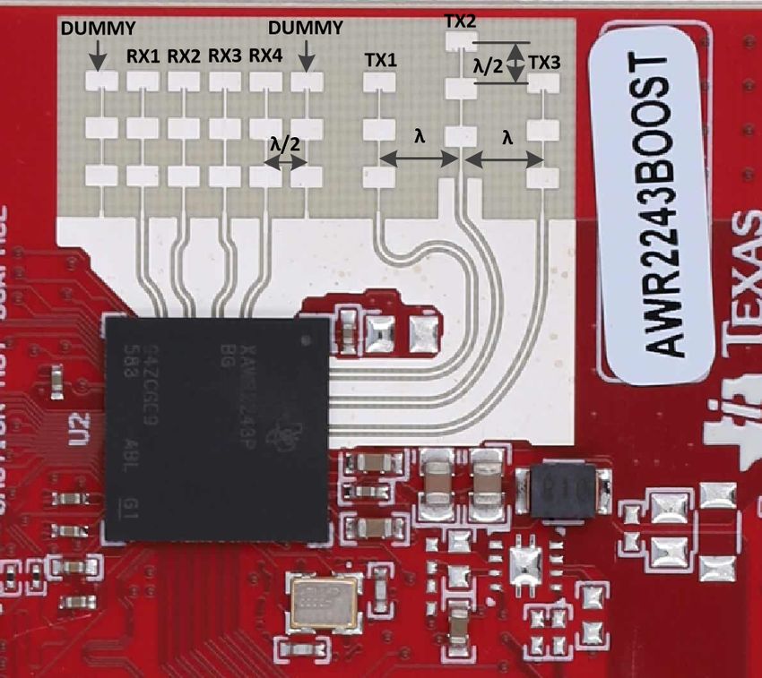
The BoosterPack includes onboard etched antennas for the four receivers and three transmitters, which enables
tracking multiple objects with their distance and angle information. This antenna design enables estimation of
both azimuth and elevation angles, which enables object detection in a 3-D plane (see Figure 2-9).
Figure 2-9. PCB Antenna
The antenna peak gain is > 10.5 dBi across the frequency band of 76 to 81 GHz. The radiation pattern of the
antenna in the horizontal plan (H-plane) and elevation plan (E-plane) is as shown in Figure 2-10 and Figure 2-11.
SPRUIT8D – FEBRUARY 2020 – REVISED FEBRUARY 2021 AWR2243 Evaluation Module (AWR2243BOOST) mmWave Sensing Solution 17
Submit Document Feedback
Copyright © 2021 Texas Instruments IncorporatedHardware www.ti.com
Figure 2-10. Antenna Pattern in H-Plane
Figure 2-11. Antenna Pattern in E-Plane
18 AWR2243 Evaluation Module (AWR2243BOOST) mmWave Sensing Solution SPRUIT8D – FEBRUARY 2020 – REVISED FEBRUARY 2021
Submit Document Feedback
Copyright © 2021 Texas Instruments Incorporatedwww.ti.com Hardware
2.7 Jumpers, Switches, and LEDs
2.7.1 Sense On Power Jumpers
The AWR2243 device can be set to operate in three different modes, based on the state of the SOP (sense on
power) lines (see Figure 2-12). These lines are only sensed during boot up of the AWR device. The state of the
device is described by Table 2-4.
A closed jumper refers to a 1 and an open jumper refers to a 0 state of the SOP signal going to the AWR device.
Table 2-4. SOP Modes
Reference Use Comments
P3 (SOP 2)
101 (SOP mode 5) = Flash programming
P2 (SOP 1) SOP[2:0] 001 (SOP mode 4) = Functional mode
011 (SOP mode 2) = Dev mode
P4 (SOP 0)
Figure 2-12. SOP Jumpers
2.7.2 Current Measurement
The P5 jumper enables measurement of the current being consumed by the reference design (AWR device +
PMIC + LDOs) at the 5-V level.
To measure the current, R118 must be removed and a series ammeter can be put across the P5 pins (see
Figure 2-13).
Figure 2-13. Current Measurement Point
SPRUIT8D – FEBRUARY 2020 – REVISED FEBRUARY 2021 AWR2243 Evaluation Module (AWR2243BOOST) mmWave Sensing Solution 19
Submit Document Feedback
Copyright © 2021 Texas Instruments IncorporatedHardware www.ti.com
2.7.3 Push Buttons and LEDs
Table 2-5 and Table 2-6 list the push button and LED uses, respectively.
Table 2-5. Push Buttons
Reference Use Comments Image
This button is used to reset the
radar device. This signal is also
brought out on the 20-pin
connector and 60-pin HD
SW2 RESET connector, so that an external
processor can control the AWR
device.
The onboard XDS110 can also
use this reset.
When this button is pushed, the
SW1 GPIO_1
GPIO_1 is pulled to Vcc.
Table 2-6. LEDs
Reference Color Use Comments Image
This LED indicates the
DS2 Red 5-V supply indication
presence of the 5-V supply.
This LED is used to indicate
the state of nRESET pin. If
this LED is on, the device is
DS4 Yellow nRESET
out of reset. This LED glows
only after the 5-V supply is
provided.
This LED turns on if there is
DS1 Red NERR_OUT any hardware error in the
AWR device.
This LED turns on when the
DS3 Yellow GPIO_1
GPIO is logic-1.
2.7.4 Selection Between SPI and CAN Interface
The AWR2243BOOST contains a SPI/CAN selector switch (S1) shown in Figure 2-14. However, the AWR2243
does not support CAN communication, so this switch should always be set to the ‘SPI’ position to bring out the
SPI interface to the HD connector (J1). For more details on the HD connector,refer to Section 2.4.2.
20 AWR2243 Evaluation Module (AWR2243BOOST) mmWave Sensing Solution SPRUIT8D – FEBRUARY 2020 – REVISED FEBRUARY 2021
Submit Document Feedback
Copyright © 2021 Texas Instruments Incorporatedwww.ti.com Hardware
Figure 2-14. S1 Switch to Select Between SPI or CAN Interface
SPRUIT8D – FEBRUARY 2020 – REVISED FEBRUARY 2021 AWR2243 Evaluation Module (AWR2243BOOST) mmWave Sensing Solution 21
Submit Document Feedback
Copyright © 2021 Texas Instruments IncorporatedHardware www.ti.com
This page intentionally left blank.
22 AWR2243 Evaluation Module (AWR2243BOOST) mmWave Sensing Solution SPRUIT8D – FEBRUARY 2020 – REVISED FEBRUARY 2021
Submit Document Feedback
Copyright © 2021 Texas Instruments Incorporatedwww.ti.com Design Files and Software Tools
Chapter 3
Design Files and Software Tools
For Rev A boards:
• AWR2243BOOST Schematics, Assembly, and BOM Details
• AWR2243BOOST Design Database and Layout Details
Note
Boards with a Rev 'B' sticker have had capacitor C56 (VBGAP decoupling capacitor) changed from
0.22 µF to 0.047 µF (part number CGA2B3X7R1H473K050BB). TI recommends that customers
incorporate this change with an equivalent capacitor in their designs.
3.1 LDO Bypass Requirement
The AWR2243BOOST uses a 1.0-V supply on the RF1 and RF2 power rails. To support the third transmitter, the
VOUT_PA output is connected to the RF2 power rail. For best performance and to prevent damage to the
device, select the 'RF LDO Bypass Enable' and 'PA LDO I/P Disable' options in the Static Configuration when
using mmWave Studio. Additionally, the LDO bypass can be configured using the AWR_RF_LDO_BYPASS_SB
API. To enable the RF LDO Bypass and PA LDO I/P Disable through the API, issue an
ar1.RfLdoBypassConfig(0x3) command.
SPRUIT8D – FEBRUARY 2020 – REVISED FEBRUARY 2021 AWR2243 Evaluation Module (AWR2243BOOST) mmWave Sensing Solution 23
Submit Document Feedback
Copyright © 2021 Texas Instruments IncorporatedDesign Files and Software Tools www.ti.com
Figure 3-1. LDO Bypass Enable
24 AWR2243 Evaluation Module (AWR2243BOOST) mmWave Sensing Solution SPRUIT8D – FEBRUARY 2020 – REVISED FEBRUARY 2021
Submit Document Feedback
Copyright © 2021 Texas Instruments Incorporatedwww.ti.com Design Revision History
Chapter 4
Design Revision History
Table 4-1. Design Revision History
PCB Revision Notes
Added switch control to move between SPI and CAN interface
Enabled, by default, the 5-V supply from the 60-pin HD connector
Enabled, by default, the SYNC_IN signal connection to the J6 connector
B Serial flash part number updated to MX25V1635FZNQ
Added series resistors on I2C lines
Removed the series diode on the NRST signal
Enabled, by default, the LDO bypass option
SPRUIT8D – FEBRUARY 2020 – REVISED FEBRUARY 2021 AWR2243 Evaluation Module (AWR2243BOOST) mmWave Sensing Solution 25
Submit Document Feedback
Copyright © 2021 Texas Instruments IncorporatedDesign Revision History www.ti.com
This page intentionally left blank.
26 AWR2243 Evaluation Module (AWR2243BOOST) mmWave Sensing Solution SPRUIT8D – FEBRUARY 2020 – REVISED FEBRUARY 2021
Submit Document Feedback
Copyright © 2021 Texas Instruments Incorporatedwww.ti.com Mechanical Mounting of PCB
Chapter 5
Mechanical Mounting of PCB
The field of view of the radar sensor is orthogonal to the PCB. The L-brackets provided with the AWR2243 EVM
kit, along with the screws and nuts help in the vertical mounting of the EVM. Figure 5-1 shows how the L-
brackets can be assembled.
Figure 5-1. Vertical Assembly of the EVM
SPRUIT8D – FEBRUARY 2020 – REVISED FEBRUARY 2021 AWR2243 Evaluation Module (AWR2243BOOST) mmWave Sensing Solution 27
Submit Document Feedback
Copyright © 2021 Texas Instruments IncorporatedMechanical Mounting of PCB www.ti.com
This page intentionally left blank.
28 AWR2243 Evaluation Module (AWR2243BOOST) mmWave Sensing Solution SPRUIT8D – FEBRUARY 2020 – REVISED FEBRUARY 2021
Submit Document Feedback
Copyright © 2021 Texas Instruments Incorporatedwww.ti.com PCB Storage and Handling Recommendations
Chapter 6
PCB Storage and Handling Recommendations
The immersion silver finish of the PCB provides a better high-frequency performance but is also prone to
oxidation in an open environment. This oxidation causes the surface around the antenna region to blacken. To
avoid this effect, store the PCB in an ESD cover and keep it at controlled room temperature with low humidity
conditions. All ESD precautions must be taken while using and handling the EVM.
SPRUIT8D – FEBRUARY 2020 – REVISED FEBRUARY 2021 AWR2243 Evaluation Module (AWR2243BOOST) mmWave Sensing Solution 29
Submit Document Feedback
Copyright © 2021 Texas Instruments IncorporatedPCB Storage and Handling Recommendations www.ti.com
This page intentionally left blank.
30 AWR2243 Evaluation Module (AWR2243BOOST) mmWave Sensing Solution SPRUIT8D – FEBRUARY 2020 – REVISED FEBRUARY 2021
Submit Document Feedback
Copyright © 2021 Texas Instruments Incorporatedwww.ti.com Regulatory Information
Chapter 7
Regulatory Information
Developers and integrators that incorporate the chipset in any end products are responsible for obtaining
applicable regulatory approvals for such an end product.
The European RF exposure radiation limit is fulfilled if a minimum distance of 5 cm between the users body and
the radio transmitter is respected.
Note
The EUT has been tested in the 76 – 77 GHz band (2 Tx at a time) at a maximum peak power of 26
dBm EIRP, and in the 77 – 81 GHz band (1 Tx at a time) with maximum peak power of 21 dBm EIRP
across the temperature range of –20°C to 60°C.
SPRUIT8D – FEBRUARY 2020 – REVISED FEBRUARY 2021 AWR2243 Evaluation Module (AWR2243BOOST) mmWave Sensing Solution 31
Submit Document Feedback
Copyright © 2021 Texas Instruments IncorporatedRevision History www.ti.com
Revision History
NOTE: Page numbers for previous revisions may differ from page numbers in the current version.
Changes from May 1, 2020 to February 28, 2021 (from Revision C (April 2020) to Revision D
(February 2021)) Page
• Added Note.......................................................................................................................................................10
• Updated Selection Between SPI and CAN Interface section............................................................................20
32 AWR2243 Evaluation Module (AWR2243BOOST) mmWave Sensing Solution SPRUIT8D – FEBRUARY 2020 – REVISED FEBRUARY 2021
Submit Document Feedback
Copyright © 2021 Texas Instruments IncorporatedIMPORTANT NOTICE AND DISCLAIMER
TI PROVIDES TECHNICAL AND RELIABILITY DATA (INCLUDING DATASHEETS), DESIGN RESOURCES (INCLUDING REFERENCE
DESIGNS), APPLICATION OR OTHER DESIGN ADVICE, WEB TOOLS, SAFETY INFORMATION, AND OTHER RESOURCES “AS IS”
AND WITH ALL FAULTS, AND DISCLAIMS ALL WARRANTIES, EXPRESS AND IMPLIED, INCLUDING WITHOUT LIMITATION ANY
IMPLIED WARRANTIES OF MERCHANTABILITY, FITNESS FOR A PARTICULAR PURPOSE OR NON-INFRINGEMENT OF THIRD
PARTY INTELLECTUAL PROPERTY RIGHTS.
These resources are intended for skilled developers designing with TI products. You are solely responsible for (1) selecting the appropriate
TI products for your application, (2) designing, validating and testing your application, and (3) ensuring your application meets applicable
standards, and any other safety, security, or other requirements. These resources are subject to change without notice. TI grants you
permission to use these resources only for development of an application that uses the TI products described in the resource. Other
reproduction and display of these resources is prohibited. No license is granted to any other TI intellectual property right or to any third party
intellectual property right. TI disclaims responsibility for, and you will fully indemnify TI and its representatives against, any claims, damages,
costs, losses, and liabilities arising out of your use of these resources.
TI’s products are provided subject to TI’s Terms of Sale (https:www.ti.com/legal/termsofsale.html) or other applicable terms available either
on ti.com or provided in conjunction with such TI products. TI’s provision of these resources does not expand or otherwise alter TI’s
applicable warranties or warranty disclaimers for TI products.IMPORTANT NOTICE
Mailing Address: Texas Instruments, Post Office Box 655303, Dallas, Texas 75265
Copyright © 2021, Texas Instruments IncorporatedYou can also read