Oracle's SPARC T8 and SPARC M8 Server Architecture - Software in Silicon: Enabling Secure Infrastructures for the Real-Time Enterprise
←
→
Page content transcription
If your browser does not render page correctly, please read the page content below
Oracle’s SPARC T8 and SPARC M8 Server Architecture
Software in Silicon: Enabling Secure Infrastructures
for the Real-Time Enterprise
ORACLE WHITE PAPER   |   JANUARY 2022
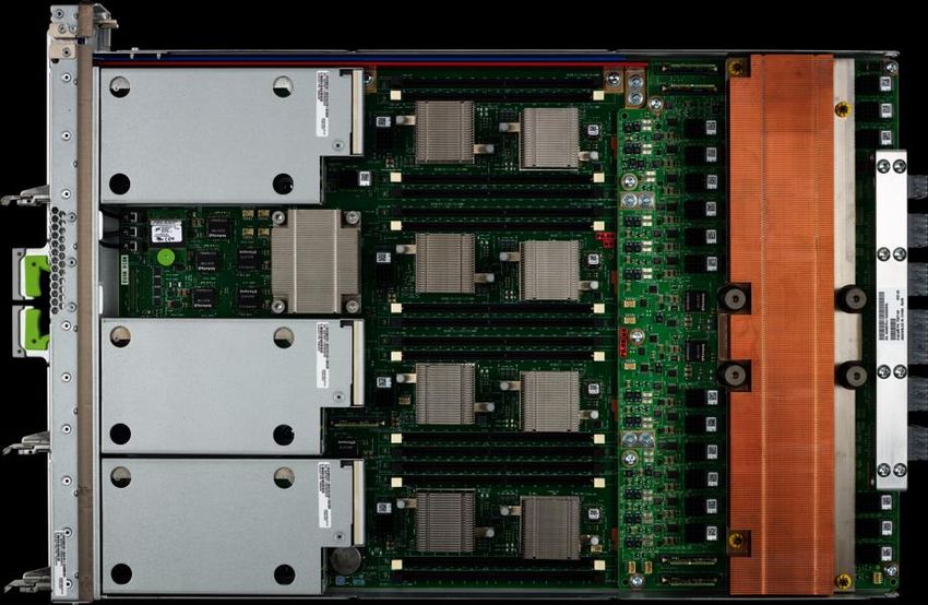
Table of Contents

Introduction                                                 1

Comparison of Features                                       3

SPARC M8 Processor                                           5

    SPARC M8 Processor Architecture                          6

    Processor Core and Cache Architecture                    7

    Software in Silicon Technology                           8

         In-Memory Query Acceleration                        9

         In-Line Decompression                               10

         Java Stream Acceleration                            10

         Oracle Numbers Acceleration                         11

         Cryptographic Acceleration                          11

         Silicon Secured Memory                              12

SPARC M8 Processor–Based Server Family Overview              14

    Memory Subsystem                                         14

    I/O Subsystem                                            15

         I/O Controller ASIC                                 15

         NVM Express Technology                              15

         Embedded USB Storage and Oracle Solaris Boot Pool   16

    PCIe Adapter Cards                                       16

SPARC T8-1, T8-2, and T8-4 Servers                           16

    SPARC T8-1 Server                                        17

    SPARC T8-2 Server                                        19

ORACLE’S SPARC T8 AND SPARC M8 SERVER ARCHITECTURE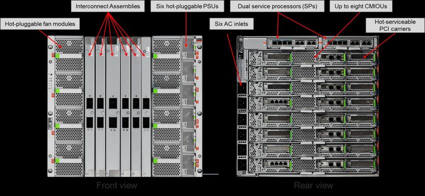
SPARC T8-4 Server                                       21

SPARC M8-8 Server                                           24

    Server Components                                       24

         CPU, Memory, and I/O Unit Chassis                  24

         CPU, Memory, and I/O Unit Boards                   25

         Interconnect Assembly                              26

         Service Processors and Service Processor Modules   26

         System Rack and Power Distribution Units           26

    SPARC M8-8 Server Architecture                          26

         SPARC M8-8 Server with a Single Physical Domain    27

         SPARC M8-8 Server with Two Physical Domains        28

Oracle Solaris                                              30

Virtualization                                              32

Systems Management                                          34

    Oracle ILOM and Service Processor                       34

    Power Management                                        35

    Oracle Enterprise Manager Ops Center                    36

Reliability, Availability, and Serviceability               36

    Advanced Reliability Features                           37

    Error Detection, Diagnosis, and Recovery                37

    Redundant and Hot-Serviceable Components                37

Conclusion                                                  38

For More Information                                        39

ORACLE’S SPARC T8 AND SPARC M8 SERVER ARCHITECTURE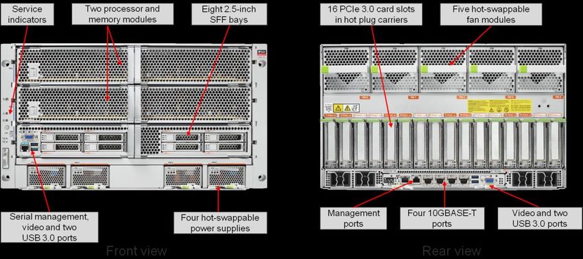
Introduction
Modern technology initiatives are driving IT infrastructure in a new direction. Big data, social business,
mobile applications, the cloud, and real-time analytics all require forward-thinking solutions and
enough compute power to deliver the performance required in a rapidly evolving digital marketplace.
Customers increasingly drive the speed of business, and organizations need to engage with customers
on their terms. The need to manage sensitive information with high levels of security as well as
capture, analyze, and act upon massive volumes of data every hour of every day has become critical.

These challenges will dramatically change the way that IT systems are designed, funded, and run
compared to the past few decades. Databases and Java have become the de facto language in which
modern, cloud-ready applications are written. The massive explosion in the volume, variety, and
velocity of data increases the need for secure and effective analytics so that organizations can make
better and quicker decisions. Complex IT infrastructure poses an impediment by becoming more
difficult and expensive to maintain at precisely the moment that organizations are under pressure to
drive down costs, increase operating efficiencies, and deliver innovative technologies that can
generate new revenue streams. Data security can no longer be treated as an afterthought, because
billions of dollars are lost each year to computer intrusions.

1 | ORACLE’S SPARC T8 AND SPARC M8 SERVER ARCHITECTURE

Oracle’s new SPARC M8 processor–based servers take server technology to new levels with Oracle’s
second generation Software in Silicon technology. Offering both database and Java application
acceleration and security, these servers offer Data Analytics Acceleration (DAX) units for in-memory
analytics on compressed data, as well as Silicon Secured Memory technology and full-speed wide-key
encryption. The SPARC M8 processor further improves efficiency with an architecture that supports up
to 256 threads in as little as 2U of space. The SPARC M8 processor also sports improved per-thread
performance; reliability, availability, and serviceability (RAS) capabilities; and power efficiency, plus
higher memory and I/O bandwidths than competitors’ designs.

Oracle’s SPARC M8 processor–based servers power the real-time enterprise with the most efficient
platforms in the world, allowing organizations to compete in today’s digital marketplace, save money
and time, and boost their bottom line. At the same time, Oracle’s technology innovation creates value
and drives lower costs and higher ROI for organizations. Based on SPARC M8 processor advances,
the new SPARC server family from Oracle (Figure 1) scales from one to eight SPARC M8 processors.
These servers constitute a flexible and extensible product family with very high levels of integration to
help improve security, lower costs, and increase reliability. An optimized system design provides
support for all enterprise services and application types. Uniformity of management interfaces and
adoption of standards also help reduce administrative costs, while innovative chassis design provides
improved density, efficiency, and economy for modern data centers.

       SPARC T8-1 server           SPARC T8-2 server            SPARC T8-4 server   SPARC M8-8 server

Figure 1. Oracle’s SPARC M8 processor–based server product family.

2 | ORACLE’S SPARC T8 AND SPARC M8 SERVER ARCHITECTURE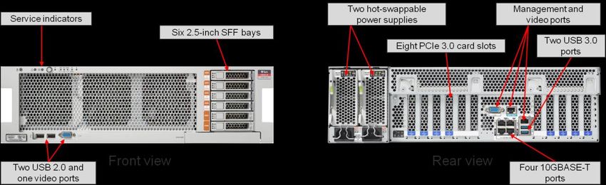
Comparison of Features
Table 1 provides a feature comparison of the SPARC T8-1, T8-2, T8-4, and M8-8 servers.

TABLE 1. SPARC M8 PROCESSOR–BASED SERVER FEATURES COMPARISON.

                            SPARC T8-1                 SPARC T8-2                SPARC T8-4                          SPARC M8-8
Feature
                                Server                     Server                    Server                               Server

Form factor                      2U,                       3U,                       6U,                              System Rack:
                           737 mm / 29” deep        753 mm / 29.6” deep       835 mm / 32.9” deep                     600 mm wide,
                                                                                                                     1,200 mm deep,
                                                                                                                     2 m / 78.7” high
                                                                                                                       Standalone:
                                                                                                                           10U,
                                                                                                                    813 mm / 32” deep

Physical domains                                              1                                                        1 or 2 (static)

                                                  32-core 5.0 GHz SPARC M8 processor, 64 MB level 3 shared cache
                                                                      Up to 256 threads per processor
                                                                          Silicon Secured Memory
Processor                     32 DAX engines for In-Memory Query Acceleration, In-Line Decompression, and Java streams acceleration
                         Encryption instruction accelerators in each core with direct support for 16 industry-standard cryptographic algorithms
                         plus random number generation: AES, Camellia, CRC32c, DES, 3DES, DH, DSA, ECC, MD5, RSA, SHA-1, SHA-3,
                                                                SHA-224, SHA-256, SHA-384, SHA-512

Processor quantity                  1                         2                       2 or 4                                2–8

Maximum cores                      32                        64                        128                                  256

Maximum threads                    256                       512                      1,024                                2,048

                          16 GB, 32 GB, 64 GB, or 128 GB DDR4-2400
                                                                                    32 GB, 64 GB, or 128 GB DDR4-2400 memory DIMMs
                                       memory DIMMs
Memory
                              8 or 16 DIMMs per processor, DIMM sparing is a standard feature increasing system reliability and uptime.1

                               Max. 2 TB                 Max. 4 TB                  Max. 8 TB                           Max. 16 TB
Memory capacity1
                              Min. 128 GB               Min. 256 GB               Min. 256 GB                          Min. 512 GB

Internal 2.5-inch
                                    8                         6                         8                                   NA
disk drive bays

                         One integrated SAS3
                            HBA with RAID           Two integrated SAS3       Two integrated SAS3
SAS support for          0/1/10/1E supporting         HBAs with RAID            HBAs with RAID
internal 2.5-inch         up to eight 2.5-inch      0/1/10/1E supporting      0/1/10/1E supporting                          NA
disk drive bays          SAS hard-disk drives       up to six (2 + 4) SAS    up to eight (4 + 4) SAS
                         (HDDs) or solid-state         HDDs or SSDs              HDDs or SSDs
                             drives (SSDs)

                              One optional           One or two optional
                                                                               Two optional PCIe
NVMe support for           factory-configured         factory-configured
                                                                             switches supporting up
internal 2.5-inch             PCIe switch               PCIe switches                                                       NA
                                                                                 to eight (4 + 4)
disk drive bays          supporting up to four      supporting up to four
                                                                              2.5-inch NVMe SSDs
                         2.5-inch NVMe SSDs         2.5-inch NVMe SSDs

      1.      Raw memory capacities. DIMM sparing is enabled with fully populated memory and reserves one sixteenth of memory capacity. DIMM
              sparing enables automatic retirement of an entire DIMM without interrupting system operation, causing loss of memory capacity, or
              changing error protection capability.

3 | ORACLE’S SPARC T8 AND SPARC M8 SERVER ARCHITECTURE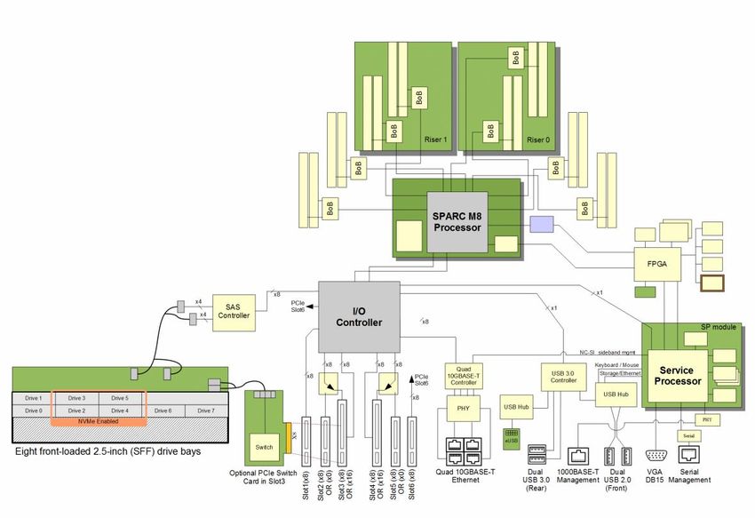
TABLE 1. SPARC M8 PROCESSOR–BASED SERVER FEATURES COMPARISON (CONTINUED).

                            SPARC T8-1                 SPARC T8-2                  SPARC T8-4                        SPARC M8-8
Feature
                                Server                     Server                     Server                              Server

Maximum number
of Oracle Flash
Accelerator F640                   6                          6                          8                                   12
PCIe Cards
(NVMe)

Removable media                               External DVD connected via USB                             No DVD (accessed via USB and rKVMS)

                                                                                                             Two Ethernet 1000Base-T ports2
                                               One Ethernet 1000Base-T port2
Management ports                                                                                                    (active/standby)
                                                     One serial RJ45 port
                                                                                                          Two serial RJ45 ports (active/standby)

                        One HD-15 VGA video                  Two HD-15 VGA video ports
Video ports                                                                                                                 NA
                               port

                                       Two USB 2.0 (front) and
USB ports                                                                       Four USB 3.0 ports                          NA
                                       two USB 3.0 (rear) ports

                                              Four integrated 10GBase-T ports3
Ethernet                                                                                                         Via PCIe adapters cards
                                              One integrated Ethernet controller

                                6 slots                     8 slots           16 hot-pluggable slots
                                                                                                                          Up to 24
                        Six x8 slots, or two x16     Four x8 and four x16     Eight x8 and eight x16                 hot-pluggable slots
PCIe 3.0
                            and two x8 slots                 slots                     slots
low-profile slots                                                                                              Three x16 slots per processor
                         Supported by 4 PCIe         Supported by 8 PCIe      Supported by 12 PCIe
                                                                                                              One PCIe root complex per slot
                           root complexes              root complexes            root complexes

Total PCIe root
                                   5                          10                         20                                Up to 32
complexes

                          2 redundant (1+1)           2 redundant (1+1)         4 redundant (N+N)
Redundant power           hot-swappable AC            hot-swappable AC          hot-swappable AC             6 redundant (N+N) hot-swappable
supplies                   1,200 W power               2,000 W power              3,000 W power                 AC 3,000 W power supplies
                               supplies                    supplies                  supplies

N+1 redundant
                         4 dual-fan modules,                                   5 dual-fan modules,
hot-swappable                                         6 fans, top loading                                     8 dual-fan modules, front loading
                             top loading                                           rear loading
fans

                       Oracle recommends Oracle Solaris 11.3 or later for enhanced performance and functionality, including features
                       enabled by Software in Silicon technology
                       Control, root, and I/O domains: Oracle Solaris 11.3 SRU 24 or later4
                       The following versions are supported within guest domains:
Operating system
                       » Oracle Solaris 11.3 SRU 24 or later4
                       » Oracle Solaris 10 1/135
                       Applications certified for Oracle Solaris 8 or Oracle Solaris 9 only may run in an Oracle Solaris 8 or Oracle Solaris 9
                       branded zone running within an Oracle Solaris 10 guest domain.

      2.      1000Base-T auto-negotiates to 10 Mb/sec, 100 Mb /sec, and 1 Gb/sec, full-duplex only.

      3.      10GBase-T auto-negotiates to 100 Mb/sec, 1 Gb/sec, and 10 Gb/sec, full-duplex only. Jumbo frames are supported, up to 15,500 bytes.
      4.      Versions of Oracle Solaris 11 prior to 11.3 SRU 23 are not supported on SPARC M8 processor–based servers.
      5.      Plus required patches.

4 | ORACLE’S SPARC T8 AND SPARC M8 SERVER ARCHITECTURE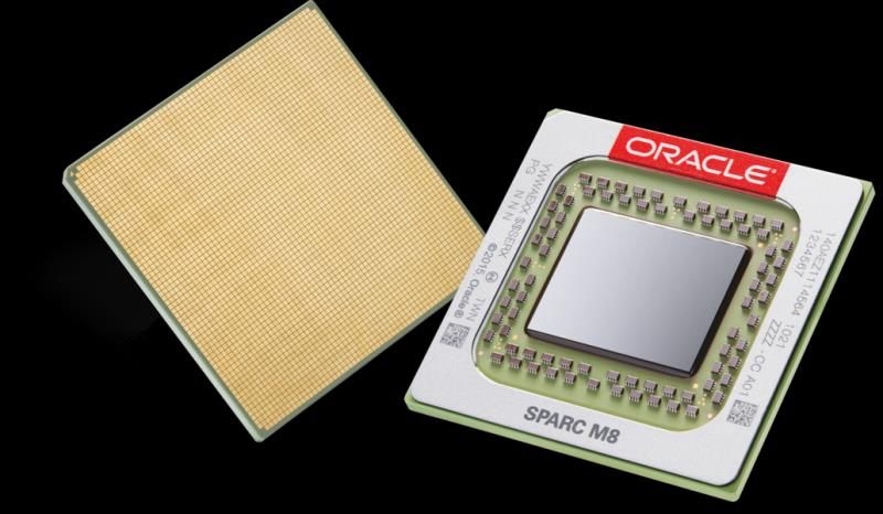
SPARC M8 Processor
With its second-generation Software in Silicon capabilities coupled with a new core design, Oracle’s SPARC M8
processor delivers world-record processing speed and revolutionary protection against malware and software errors.

The SPARC M8 processor incorporates hardware units that accelerate specific software functions or primitives.
These on-chip Data Analytics Accelerator (DAX) units offload database query processing, perform real-time data
decompression, and accelerate Java streams. In-Memory Query Acceleration delivers performance that is up to
seven times faster compared to other processors. The In-Line Decompression feature allows up to two times more
data to be stored in the same memory footprint, without a performance penalty. The new core in the SPARC M8
processor also includes Oracle Numbers units that accelerate processing of real numbers in Oracle Database.

The Silicon Secured Memory feature of the SPARC M8 processor (Figure 2) provides real-time data integrity
checking to guard against pointer-related software errors and malware. It replaces very costly software
instrumentation with low-overhead hardware monitoring. Silicon Secured Memory enables applications to identify
erroneous or unauthorized memory access, diagnose the cause, and take appropriate recovery actions. The
SPARC M8 processor has enhanced cryptographic instruction accelerators integrated directly into each processor
core. These accelerators enable high-speed encryption for 16 industry-standard ciphers and hashes, eliminating the
performance and cost barriers typically associated with secure computing.

                                                                            .

Figure 2. The SPARC M8 processor combines 32 cores along with second-generation Software in Silicon features to accelerate
application and database performance.

The per-thread performance is improved with the new core, enhanced on-chip L2 and L3 cache design, and
increased processor frequency. The 64 MB L3 cache is fully shared and hot cache lines are migrated to the closest
partition to minimize latency and maximize performance. The architecture of the core and caches is ideal for server
virtualization and pluggable databases. System administration and performance tuning are easier, because the
design minimizes interaction between logical domains or between databases. The processor can dynamically trade
per-thread performance for throughput by running up to 256 threads, or it can run fewer higher-performance threads
by devoting more resources to each thread. This flexibility allows the system to balance overall throughput versus
per-thread performance for optimal results.

5 | ORACLE’S SPARC T8 AND SPARC M8 SERVER ARCHITECTURE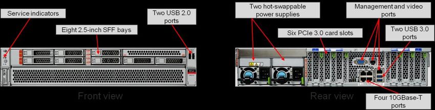
The 32-core SPARC M8 processor is binary-compatible with earlier SPARC processors. It is ideal for virtualized
cloud computing environments, supporting a large number of virtual machines and delivering excellent multithreaded
performance. This processor enables organizations to rapidly scale the delivery of new network services with
maximum efficiency and predictability.

Table 2 provides a comparison between Oracle’s SPARC M8, SPARC M7, SPARC M6, and SPARC T5 processors.

TABLE 2. SPARC M8, SPARC M7, SPARC M6, AND SPARC T5 PROCESSOR FEATURE COMPARISON.

                                      SPARC M8                SPARC M7                  SPARC M6                 SPARC T5
Feature
                                       Processor               Processor                 Processor                Processor

CPU frequency                            5.0 GHz                4.13 GHz                  3.6 GHz                   3.6 GHz

Out-of-order execution                      Yes                    Yes                       Yes                      Yes
Instruction issue width                      4                      2                         2                        2
Data/instruction prefetch                   Yes                    Yes                       Yes                      Yes

SPARC core                           Fifth generation       Fourth generation          Third generation         Third generation

Cores per processor                         32                      32                       12                        16
Threads per core                             8                      8                         8                        8
Threads per processor                       256                    256                       96                       128

Sockets in systems                        Up to 8                Up to 16                 Up to 32                  Up to 8

Memory per processor             Up to 16 DDR4 DIMMs      Up to 16 DDR4 DIMMs      Up to 32 DDR3 DIMMs       Up to 16 DDR3 DIMMs

                                                            16 KB L1 four-way
                                    32 KB L1 four-way
                                                             instruction cache
                                     instruction cache                                16 KB L1 four-way        16 KB L1 four-way
                                                          16 KB L1 four-way data       instruction cache        instruction cache
                                 16 KB L1 four-way data
                                                                  cache
                                         cache                                     16 KB L1 four-way data    16 KB L1 four-way data
                                                             Shared 256 KB L2              cache                     cache
                                    Shared 256 KB L2
Caches                                                      four-way instruction
                                   four-way instruction                             128 KB L2 eight-way       128 KB L2 eight-way
                                                          cache (per quad cores)
                                 cache (per quad cores)                                   cache                     cache
                                                             Shared 256 KB L2
                                128 KB L2 eight-way data
                                                         eight-way data cache (per Shared 48 MB L3 twelve-      Shared 8 MB L3
                                    cache (per core)                                     way cache             sixteen-way cache
                                                                 core pair)
                                Shared 64 MB (L3) cache
                                                         Shared 64 MB (L3) cache

Large page support1                       16 GB                   16 GB                     2 GB                     2 GB

Power management
                                      Half of the chip     A quarter of the chip         Entire chip               Entire chip
granularity

Technology                          20 nm technology        20 nm technology          28 nm technology         28 nm technology

1. Large page support with Oracle Solaris 11.3

SPARC M8 Processor Architecture
In order to deliver commercial workloads with appropriate levels of throughput, the SPARC M8 processor
implements a new core and cache hierarchy coupled with other improvements that can provide up to twice the
processing speed of the competition. Power management continues to be key to the increased in-system
performance, and dynamic voltage frequency scaling (DVFS) is provided.

6 | ORACLE’S SPARC T8 AND SPARC M8 SERVER ARCHITECTURE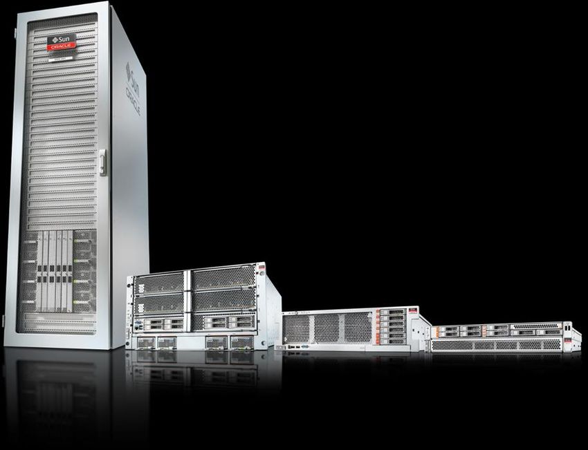
Figure 3 illustrates the architecture of the SPARC M8 processor. The processor contains 32 cores with fully shared
L3 cache. Four memory controller units (MCUs) are provided, with each connecting to the buffer-on-board (BoB)
ASICs via high-speed links. The BoB has two DDR4 channels each connecting to a single memory DIMM. A total of
up to 16 DDR4 DIMMs are supported per SPARC M8 processor.

SPARC M8 processor is capable of eight-way glueless scaling using an inclusive directory. Eight coherency links
(CLs) are provided for connectivity and coherency with other SPARC M8 processors. Two I/O links (ILs) connect to
the I/O controller ASICs in the SPARC M8 processor–based servers. Up to eight SPARC M8 processors can be
connected in a single symmetric multiprocessing (SMP) system without additional logic.

Figure 3. The SPARC M8 processor features 32 cores, which are grouped in two partitions, four memory controller units (MCUs),
and eight Data Analytics Accelerators (DAX) units.

Processor Core and Cache Architecture
The SPARC M8 processor core is four-wide issue, out-of-order with up to 192 instructions in-flight, and supports up
to eight hardware threads. The core provides dynamic threading to optimize for the highest possible per-thread
performance. Software can activate up to eight hardware threads (strands) on each core via critical threads
optimization. The processor hardware then dynamically and seamlessly allocates core resources among the active
strands.

Processor cores and the last level cache are organized as two partitions each containing 16 cores and 32 MB of L3
cache. Each core has its own 32 KB L1 instruction cache, 16 KB L1 data cache, and 128 KB L2 data cache. Four
cores then share a 256 KB L2 instruction cache. There is total of 64 MB L3 cache per processor that is fully shared,
16-way set-associative, and inclusive of all inner caches. Any L3 partition may serve a request from any of the 32
cores of the SPARC M8 processor. Hot cache lines are migrated to the closest L3 cache partition to optimize for
performance.

7 | ORACLE’S SPARC T8 AND SPARC M8 SERVER ARCHITECTURE
The memory management unit (MMU) in the core provides a hardware table walk (HWTW) and supports 8 KB,
64 KB, 4 MB, 256 MB, and 16 GB pages.

Software in Silicon Technology
Most processor chip development focuses on better and faster general-purpose processing. Several years ago,
Oracle initiated a revolutionary project to move in-memory database functions directly onto the chip, with hardwired
protection for data in memory. By innovating at the processor, system, and application levels, Oracle is in a unique
position to optimize application performance through this approach. The SPARC M7 processor was the first design
to capitalize on this ability by introducing Software in Silicon functionality integrated into the processor itself. The
SPARC M8 processor builds on that and delivers second-generation Software in Silicon technology.

The SPARC M8 processor incorporates on-chip accelerators to offload in-memory database query processing,
perform real-time data decompression, and accelerate Java streams. The enhanced cryptographic instruction
accelerators and the new Oracle Numbers units are integrated directly into each processor core. Together, the
following Software in Silicon features deliver significant advantages for security, performance, and efficiency,
including the following:

» In-Memory Query Acceleration provided by DAX units delivers performance that is up to seven times faster
  compared to other processors.
» In-Line Decompression enables storing up to two times more data in the same memory footprint, without a
  performance penalty.
» Java stream acceleration allows Java 8 applications to use a new Stream library to leverage the DAX units,
  improving streamline analytics and providing significant performance gains on Java streams operations.
» Oracle Numbers units leverage unique on-chip accelerators to improve the performance of arithmetic
  operations done on the Oracle Number data type, which is a primitive data type unique to Oracle Database.
» Silicon Secured Memory provides real-time data integrity checking to guard against pointer-related software
  errors and malware, replacing very costly software instrumentation with low-overhead hardware monitoring.
  Silicon Secured Memory enables applications to identify erroneous or unauthorized memory access, diagnose the
  cause, and take appropriate recovery actions.
» Cryptographic acceleration helps eliminate the performance and cost barriers typically associated with secure
  computing—which is increasingly essential for modern business operation.

In addition to the cryptographic instruction accelerators and the Oracle Numbers units in every core, the SPARC M8
processor contains eight second-generation DAX units, each with four pipelines (engines). These engines can
process 32 independent data streams, offloading the processor cores to do other work. The DAX engines can
process query functions such as decompress, scan, filter, and join.

The DAX units use very low-overhead interprocess communication and extremely fast atomic operations. For
example, DAX units located on different processors can exchange messages and access remote memory locations,
exchanging locks without CPU involvement. Utilizing this functionality requires Oracle Database 12c with the
Oracle Database In-Memory option and Oracle Solaris 11.3 or later. The sections that follow describe Software in
Silicon features enabled by the on-chip accelerators.

Existing applications can be enabled with Silicon Secured Memory, without recompiling, by linking with the correct
Oracle Solaris libraries and being verified in a test environment. Open Oracle Solaris APIs are available for software
developers to leverage Silicon Secured Memory and DAX technologies.

8 | ORACLE’S SPARC T8 AND SPARC M8 SERVER ARCHITECTURE
In-Memory Query Acceleration
In-Memory Query Acceleration was designed to work with Oracle Database In-Memory, which was architected with
fast analytics response as its primary design tenet. The traditional way of storing and accessing data in a database
employs a row format. This approach works well for transactional workloads that are subject to frequent inserts and
updates as well as for reporting style queries. However, analytics run best on a columnar format. With Oracle
Database In-Memory, it is possible to have a dual-format architecture that provides both row format for online
transaction processing (OLTP) operations and column format for analytic operations.1

Oracle Database In-Memory populates the data in an in-memory column store. A set of compression algorithms is
automatically run on the data being stored in the in-memory column, providing storage economies. Moreover, when
a query is run, it scans and filters data in its compressed format, eliminating the need to decompress the data. The
in-memory column store creates in-memory compression units (IMCUs), as shown in Figure 4. The in-memory
columnar data is fragmented into these smaller IMCUs so that parallelization is possible when a query is run on the
overall data.

Figure 4. In-memory columnar data is fragmented into smaller IMCUs to enable parallelization.

When a core in the SPARC M8 processor receives a database query, the query can be offloaded to the on-chip
accelerator. Accelerated database operations include the following:

      » Select: Filter to reduce a column
      » Scan: Search (“where” clause)
      » Extract: Decompression
      » Translate: Lookup to accelerate big-to-small joins
After the query is offloaded, the core is free to resume other jobs such as higher-level SQL functions. Meanwhile,
the accelerator runs the query and places the result in the L3 cache for fast access by the core. Once the relevant
core is informed of the completion of the query, it picks up the result.

Beyond accelerating operations, the other advantage of this query offload mechanism is the massive parallelization
that is facilitated by the 32 accelerator engines within each SPARC M8 processor. Each of the 32 cores in the
processor has access to all of these accelerator engines and can use them simultaneously to run a single query in a
completely parallel fashion.

1 In-Memory Query Acceleration is supported on SPARC M8 processor–based servers with these prerequisites: Oracle Solaris 11.3 or later, Oracle
Database 12c 12.1.0.2 Bundle Patch, and the Oracle Database In-Memory option.

9 | ORACLE’S SPARC T8 AND SPARC M8 SERVER ARCHITECTURE
The mechanics of this parallelism are achieved by the processor and do not require the application code or the database to perform any extra operations. The accelerators can take data streams directly from the memory subsystem through the processor’s extremely high-bandwidth interfaces. As a result, queries can be performed on in-memory data at speeds determined by the memory interface, rather than being controlled by the cache architecture that connects to the processor cores. In-Line Decompression Compression is absolutely key to placing more data in memory and in storage. The speed of decompression is most important for database applications, where reading typically outweighs writing. Unfortunately, although the performance of decompression on today’s processors is adequate for disk access, it is slow for flash memory, and it presents an enormous bottleneck for in-memory database applications. To address this challenge, the In-Line Decompression feature is implemented in the DAX units as an integral step of the query process. The accelerators decompress data and run the query function in a single step, thus eliminating multiple reads and writes. The result is no-penalty, in-line decompression that can run at memory speeds—greater than 120 GB/second. The decompression sequence involves the following steps: » The processor core offloads query work to the accelerator, which reads the full compressed data (OZIP compression is used). » The accelerator decompresses data on the fly and evaluates the query in a single step without any additional read or write operations. » The processor core then writes out the final result as uncompressed data. Java Stream Acceleration The Java programming language has always been a pioneer in object-oriented programming, as well as in the execution of analytics applications and frameworks. Today, many Java applications make use of Collections, a Java class that allows the grouping and processing of large amounts of data efficiently in a programmer friendly manner by leveraging predefined data structures and methods. However, many of the methods from the Collections class can be very compute-intensive, especially when it comes to analyzing large amounts of in-memory data, because every element in a collection has to be computed before it can be added to the collection. As an alternative to using collections, Java 8 introduced the concept of Java streams. Java streams are conceptually fixed data structures in which elements are computed on demand and do not modify the source data. Using Java streams allows applications to process data in a declarative way, similar to SQL statements. There are many advantages on using Java streams. Doing so simplifies coding as well as the execution of operations, because streams perform computations on data only when necessary, which avoids unnecessary memory copying. Moreover, because of their underlying design, Java streams can take advantage of multithread and multicore architectures. Following are the characteristics of a stream: » Sequence of elements: A stream provides a set of elements of a specific type in a sequential manner. A stream gets/computes elements on demand. It never stores the elements. » Source: A stream takes collections, arrays, or I/O resources as its input source. » Aggregate operations: A stream supports aggregate operations such as filter, map, limit, reduce, find, match, and so on. » Pipelining: Most of the stream operations return a stream, which allows pipelining. These operations are called intermediate operations, and their function is to take input, process it, and return the output to the next stream operation. 10 | ORACLE’S SPARC T8 AND SPARC M8 SERVER ARCHITECTURE
» Automatic iterations: Stream operations do iterations internally over the source elements that are provided, in
  contrast to collections, where explicit iteration is required.
The DAX units of SPARC processors are designed to perform specialized functions—including Scan, Select,
Extract, Fill, and Translate—at blindingly fast speeds. Based on the implementation and functionality of Java
streams, they are a perfect fit for leveraging the unique features of DAX units.

Oracle has released a new Stream API to take advantage of DAX units. The library, which is available as part of the
Oracle Solaris packages, allows Java programmers to use the DAX units of the SPARC M8 processor while
leveraging the same interface as that of the standard Stream API, requiring only a minor change to the import
statement in the source files. Moreover, the library is designed to offload integer stream functions to DAX units only
when that is profitable; otherwise it will execute the normal stream operations.

DAX units provide significant advantages for processing Java streams: performance gains up to 20x on some
operations, depending on the size of the datasource and the type of operations executed on the data.

Oracle Numbers Acceleration
Oracle Database has a unique implementation of primitive data types. Each column value and constant in a SQL
statement has a data type, which is associated with a specific storage format, constraints, and a valid range of
values. The data type must always be specified for each column of a table in Oracle Database.

Specifically for fixed and floating-point numbers, Oracle Database has a unique data type called Oracle Numbers,
which can store fixed and floating-point numbers. Numbers of virtually any magnitude can be stored and are
guaranteed to be portable among different systems operating Oracle Database with up to 38 digits of precision.

Each of the 32 cores in the SPARC M8 processor includes an Oracle Numbers unit, which is specifically designed to
accelerate Oracle Numbers arithmetic performance. The Oracle Numbers data type provides four new instructions
(ONadd, ONsub, ONmul, and ONdiv) and supports natively all lengths of fixed and floating-point numbers up to 22
bytes.

Processing arithmetic operations for Oracle Numbers data is a compute-intensive task, because every operation
requires multiple instructions, and database arithmetic processes can require millions of arithmetic operations per
task. The new Oracle Numbers unit of the SPARC processor speeds up processing, taking only one instruction per
operation. This translates into significant performance gains: over a 10x improvement for large Oracle Numbers bit
lengths (over 16 bytes), thereby reducing the amount of time required to process operations and freeing the cores to
do other work.

For arithmetic-intensive workloads, such as reporting and data warehousing, this feature can provide significant
savings in resource utilization and decrease the total amount of compute nodes required for a deployment.

Cryptographic Acceleration
Enhanced security has never been more important, and SPARC processors and systems have a long history of
providing processor-based cryptographic acceleration. Each of the 32 cores in the SPARC M8 processor includes a
cryptographic instruction accelerator with the largest suite of cryptographic ciphers, hashes, key operations, and
checksums in the industry. The core supports 16 industry-standard cryptographic algorithms plus random number
generation. Accelerated cryptography is supported through the Cryptographic Framework of Oracle Solaris.

The SPARC M8 processor permits access to cryptographic cypher hardware implementations with supported
algorithms that include AES, Camellia, CRC32c, DES, 3DES, DH, DSA, ECC, MD5, RSA, SHA-1, SHA-3, SHA-224,
SHA-256, SHA-384, and SHA-512. The cyphers are implemented within the appropriate pipeline itself rather than as
a coprocessor. This approach yields a more efficient implementation of the hardware-based cyphers as well as no
privilege-level changes, resulting in a large increase in efficiency in cryptographic algorithm calculations.

11 | ORACLE’S SPARC T8 AND SPARC M8 SERVER ARCHITECTURE
In addition, database operations can make much more efficient use of the various cryptographic cyphers that are
implemented within the instruction pipeline itself. Using the built-in encryption on the SPARC M8 processor across
all layers of the Oracle stack provides greater data security with almost no loss in performance.

Silicon Secured Memory
Silicon Secured Memory in the SPARC M7 and SPARC M8 processors provides hardware-based memory
protection by placing dynamic pointer checking in hardware. Silicon Secured Memory detects and reports memory
reference errors and stops unintentional or malicious accesses to the data in memory.

Some programming languages, such as C and C++, remain vulnerable to memory corruption caused by software
errors. These kinds of memory reference bugs are extremely hard to find, and victims usually notice corrupted data
only long after the corruption has taken place. Complicating matters, databases and applications can have tens of
millions of lines of code and thousands of developers. Importantly, errors such as buffer overflows are a major
source of security exploits that can put an organization at risk.

Modern applications use many threads working on large shared-memory segments. Bugs or pointer problems in
these applications can cause highly unpredictable behavior and consume excessive amounts of an application
developer’s time to troubleshoot and diagnose. Silent data corruption and buffer overruns are two of these
difficult-to-diagnose problems. For both problems, Silicon Secured Memory dramatically reduces the time it takes for
application developers to troubleshoot memory reference bugs. For silent data corruption, Silicon Secured Memory
can facilitate immediate action to be taken by the application, preventing costly recovery efforts.

Figure 5 illustrates the problem of silent data corruption where two application threads (A and B) accidentally access
the same memory location. The color coding demarcates the memory areas that each thread should be accessing,
respectively. However, a software programming error can mean that Thread A erroneously writes into the
red-outlined area of Thread B. This error is typically not caught immediately, and it is potentially detected only when
that memory is read by Thread B. Thread B now has data that has been silently corrupted by Thread A, and the
source of the corruption is often extremely difficult to trace. This problem is extremely hard to diagnose and typically
is manifest as a software bug with potentially serious consequences.

Figure 5. Silent data corruption occurs when two threads mistakenly write to the same memory location.

12 | ORACLE’S SPARC T8 AND SPARC M8 SERVER ARCHITECTURE
Buffer overruns are an additional problem that can occur in applications. Simply stated, buffer overruns imply that an
application has erroneously started writing data beyond its allocated area (Figure 6). Through this error, sensitive
data could be leaked into other memory locations and the application would not be aware of it. An application with
malicious intent could then read all this sensitive information. Buffer overruns can present a catastrophic security
nightmare, often seen in today’s world in the form of malicious virus attacks.

Figure 6. Buffer overruns can represent a significant security risk.

Silicon Secured Memory combats these problems by using a key for each (memory) pointer to serve as the memory
version. During the process of memory allocation, a corresponding code is written into the memory as its version.
When this memory is accessed by any pointer, the key and code are compared by the hardware. If they match, the
access is legal. If they do not match, there is a memory reference error, which is caught immediately.

13 | ORACLE’S SPARC T8 AND SPARC M8 SERVER ARCHITECTURE
SPARC M8 Processor–Based Server Family Overview
The SPARC M8 processor-based servers are designed for cloud infrastructures that required high levels of security,
performance, and efficiency. These SPARC servers are ideal for database, Java, middleware, and enterprise
applications, and they offer exceptional throughput performance and memory bandwidth. This server product family
provides support for one to eight SPARC M8 processors, supporting a very broad range of applications, capabilities,
and capacities.

Common hardware features of the servers include the following:
» SPARC M8 32-core 5.0 GHz processor with second-generation Software in Silicon technology
» 32 GB, 64 GB, and 128 GB DDR4-2400 memory DIMMs (16 GB DIMMs are also available with the SPARC T8-1
  and T8-2 servers)
» PCIe 3.0 x16–capable expansion slots
» Support for NVM Express (NVMe) flash devices
» Onboard 12 Gb/sec SAS3 I/O controllers with the SPARC T8-1, T8-2, and T8-4 servers
» Embedded USB (eUSB) storage device supporting booting over InfiniBand network

Memory Subsystem
Each SPARC M8 processor supports up to16 DDR4 memory DIMMs via eight buffer-on-board (BoB) ASICs. Up to
2 TB of memory is supported per processor with sixteen 128 GB DIMMs each supported by a dedicated memory
channel. The memory links of the SPARC M8 processor have a raw bandwidth of 374 GB/sec, which is more than
enough for the raw aggregated bandwidth of 307 GB/sec that 16 DDR4-2400 channels might require.
Half-populated and fully populated memory configurations are supported. Detailed configuration policies are
discussed later in the model-specific sections of this paper.

The physical address space provided by the memory DIMMs and controlled by an individual SPARC M8 processor
is interleaved to maximize performance. Half-populated memory configurations are 8-way interleaved, and fully
populated configurations with16 DIMMs per processor are 16-way interleaved. The SPARC M8 processor also
supports a 15-way interleaved configuration. The switch from a 16-way to 15-way configuration can be done
dynamically. This capability is the basis of the feature called DIMM sparing, first introduced with the SPARC M7
processor–based servers. DIMM sparing increases system uptime by reducing the need to perform DIMM
replacement service work.

DIMM sparing is the function of removing a faulty DIMM from the configuration, thus preventing it from causing an
unplanned system interruption. By leaving one-sixteenth of the capacity of each DIMM unused, the bad DIMM can
be retired and its content remapped into the remaining 15 DIMMs. DIMM sparing is done automatically when a
DIMM is determined to be faulty, with no interruption to application services. Through this process, the system
memory capacity is unchanged and error protection remains intact after DIMM sparing is performed. The system
simply continues to run with no loss of capacity and no increased exposure to failures. Consequently, there is no
need to take the system down to service the hardware. The actual DIMM replacement process can wait until a
second DIMM in the same memory bank needs to be replaced.

DIMM sparing is enabled in SPARC M8 processor–based servers with fully populated memory configurations (16
DIMMs per processor). DIMM sparing is not supported in half-populated memory configurations. While not
recommended, it is possible to disable DIMM sparing in fully populated memory configurations.

14 | ORACLE’S SPARC T8 AND SPARC M8 SERVER ARCHITECTURE
I/O Subsystem
The SPARC M8 processor–based servers share the same basic design for the I/O subsystem. Each SPARC M8
processor is connected to one or two I/O controller ASICs via I/O links (ILs). There are two ILs on the SPARC M8
processor as well as in the I/O controller ASIC.

There are two different implementations of the connection between the SPARC M8 processor and the I/O controller
ASIC being used. In the SPARC T8-1 and SPARC M8-8 servers, each SPARC M8 processor is connected to a
single I/O controller ASIC using both ILs. The SPARC T8-2 and SPARC T8-4 servers utilize a crossover connection
scheme in order to provide connectivity to two I/O controller ASICs (and PCIe devices) even if one of the processors
or ILs is not available. In the crossover connection, one IL in the processor connects to one I/O controller, and the
other IL connects to another I/O controller. See more details in the model-specific sections of this paper.

I/O Controller ASIC
The PCIe infrastructure is provided by the I/O controller ASICs. Each ASIC provides five PCIe 3.0 root complexes
with an aggregated bandwidth of 72 GB/sec. Because the I/O controller ASIC hosts the entire PCIe fabric, it remains
intact when processors are added or removed. As a result, the PCIe device paths do not change, because the
connection to the device is fixed within the root complex provided by the I/O controller ASIC. The I/O controller ASIC
utilized in SPARC M8 processor–based servers provides significant innovation, including the following:
» Two x16 ILs connect to the SPARC M8 processor, and each IL comprises two x8 connections.
» A single lane failure is supported on each x8 IL connection.
» Each IL participates in hardware cache coherency.
» Dual-host processor failover is used in the SPARC T8-2 and T8-4 servers.
» SR-IOV compliance is provided.
» Address translation per DMA stream is provided.
» Relaxed packet ordering per DMA stream is provided.
» There are four PCIe 3.0 x16 ports, which are quadfurcatable and can be implemented as a single x16, four x4, or
  two x8 PCIe ports.
» There is one PCIe 3.0 x8 port, which is bifurcatable and can be implemented as a single x8 or two x4 PCIe ports.
» Each of the five PCIE 3.0 ports is an independent root complex.

NVM Express Technology
SPARC M8 processor–based servers provide support for the emerging flash storage technology known as NVM
Express (NVMe). The NVMe specification defines an optimized PCIe-based interface for solid-state drives (SSDs).
Utilizing nonvolatile memory, NVMe-based SSDs provide both lower latency and better throughput performance
relative to SAS or SATA-based SSDs. NVMe utilizes PCIe signaling and provides an 8 gigatransfers per second
(GT/second) x4 interface per drive, yielding approximately 4 GB/sec full-duplex bandwidth to the drive.

All SPARC M8 processor–based servers support the Oracle Flash Accelerator F640 PCIe Card—which provides an
NVMe-based SSD device on a low-profile PCIe card. The SPARC T8-1, T8-2, and T8-4 servers support internal
2.5-inch small form factor (SFF) NVMe SSDs in select drive bays that can also support SAS-based HDDs and
SSDs. A factory-configured NVMe PCIe switch card and cables are required when the SFF NVMe drives are used.
The switch card uses a x8 PCIe 3.0 interface and provides fan-out and electrical retiming functions for up to four x4
downstream links (one per NVMe drive).

NVMe devices are hot-plug capable, but OS-specific hot-plug procedures must be followed. An nvmeadm command
is provided that lets administrators list drive health and firmware level, check temperatures, get error logs, and
access SMART data, as well as conduct a security erase and perform low-level formatting.

15 | ORACLE’S SPARC T8 AND SPARC M8 SERVER ARCHITECTURE
Embedded USB Storage and Oracle Solaris Boot Pool
SPARC M7 and SPARC M8 processor–based servers support a specific boot process that allows booting from a
greater variety of devices. A conventional boot process requires that the boot devices be accessible by the system
firmware. For example, a network boot over InfiniBand has previously not been supported for that reason.

The alternate Oracle Solaris boot process includes a concept called a boot pool. A boot pool is a boot device that is
used to store boot archives. In SPARC M8 processor–based servers, one or more embedded USB (eUSB) storage
devices are grouped together to form a boot pool, making the boot pool accessible to the OpenBoot PROM
firmware. The eUSB storage is an internal USB flash memory device that is installed into the system at the factory.
SPARC T8-1, T8-2, and T8-4 servers include one eUSB device. The SPARC M8-8 server includes one eUSB
device for every CPU, memory, and I/O unit (CMIOU) chassis board, allowing the boot pool to consist of multiple,
striped eUSB storage devices.

The existence of the local boot pool allows the OpenBoot PROM firmware to load the boot archive and subsequently
mount the root file system in the root pool using iSCSI over IP over InfiniBand (IPoIB). SPARC M8 processor–based
servers also provide a fall-back mechanism for the new boot process, which can be used when the eUSB-based
boot archives are not available. A boot archive exists in the flash memory of the system service processor (SP). This
boot archive is loaded onto the SP at the factory and is intended to be used only when other means of booting are
not available.

PCIe Adapter Cards
SPARC M8 processor–based servers feature both PCIe 3.0 x8 and x16 expansion card slots. Supported options
and requirements vary by server models. At the time of this writing, available adapter cards from Oracle include the
following:

» Oracle Flash Accelerator F640 PCIe Card v2: 6.4 TB, NVMe PCIe 3.0
» Oracle Storage Dual Port 16 Gb or 32 Gb Fibre Channel PCIe HBA
» Sun Storage 16 Gb FC PCIe Universal HBA
» Oracle Dual 100 Gb Ethernet Adapter
» Oracle Quad 10 Gb or Dual 40 Gb Ethernet Adapter
» Oracle Dual Port 25 Gb Ethernet Adapter
» Sun Dual 10 GbE SFP+ PCIe 2.0 Low Profile adapter
» Oracle Quad Port 10GBase-T Adapter
» Sun Quad Port GbE PCIe 2.0 Low Profile Adapter, UTP
» Oracle Storage 12 Gb SAS PCIe HBA, external: 8 port

SPARC T8-1, T8-2, and T8-4 Servers
The SPARC T8-1, T8-2, and T8-4 servers are designed to provide breakthrough security and performance while
maximizing reliability and minimizing power consumption and complexity. These systems are ideal for scale-out
applications where high availability is provided by replicating systems with applications that support failover between
systems. With common, shared components and subsystems, a separate design is used in each of the
SPARC T8-1, SPARC T8-2, and SPARC T8-4 servers to optimize each system for its particular design point and
capabilities. The servers feature a robust chassis, component, and subassembly design; enhanced system and
component serviceability; and minimized cabling for maximized airflow.
» The SPARC T8-1 server is the entry model with a single processor. However, with 256 hardware threads and
  1 TB of memory it outperforms dual-processor alternatives. Like all the models in this server family, the

16 | ORACLE’S SPARC T8 AND SPARC M8 SERVER ARCHITECTURE
SPARC T8-1 server features the full suite of Software in Silicon features, including secure operation with Silicon
  Secured Memory and high performance with in-memory database query acceleration and In-Line Decompression.
» The SPARC T8-2 server offers twice the capacity and more resources compared to the SPARC T8-1 server. The
  dual-processor SPARC T8-2 server also includes additional availability features, such as innovative
  cross-connections between the processor and the I/O controller ASICs, dual integrated SAS controllers, and
  optional dual NVMe PCIe switches for internal NVMe SSDs.
» The SPARC T8-4 server supports up to four processors, which are mounted on the front-accessible processor
  modules. The entry configuration with two processors can easily be expanded to four processors, if needed. The
  SPARC T8-4 server also offers individually hot-pluggable PCIe cards supported with a large number of dedicated
  PCIe root complexes, making the server ideal for workload consolidation into a virtualized private cloud.

SPARC T8-1 Server
The SPARC T8-1 server is the entry model and features a single SPARC M8 processor in a 2U enclosure. Standard
features include eight onboard memory DIMM slots that are expandable to a total of 16 with optional dual mezzanine
cards (memory risers)—yielding up to 1 TB of system memory. Figure 7 illustrates the front and rear perspectives of
the SPARC T8-1 server. The server includes six low-profile PCIe 3.0 expansion slots, accessible from the rear of the
system.

The eight 2.5-inch small form factor (SFF) front-loading drive bays are all supported by an onboard 12 Gb/sec SAS
HBA, which provides RAID 0, 1, 10, and 1E protection. Oracle Solaris ZFS provides higher levels of RAID support. A
factory-configured option is available to support up to four 2.5-inch SFF NVMe SSDs. The option includes an NVMe
PCIe switch card installed in PCIe slot #3 and internal cabling to the drive cage. Mixing SAS and NVMe drives is
supported. Other standard features of the SPARC T8-1 server include the following:

» Four 10GBase-T Ethernet ports (RJ45) are provided on the back of the system, supported via an onboard
  network interface controller (NIC). Ports auto negotiates to speeds of 100 Mb/sec, 1 Gb/sec, and 10 Gb/sec, full-
  duplex only. Jumbo frames, up to 15,500 bytes, are supported.
» Two hot-swappable 1+1 power supply units (PSUs), 1200 W at 200VAC–240VAC, are inserted from the rear of
  the system.
» Four top-loading hot-swappable fan modules are provided, each with dual counter-rotating fans.
» Dual USB 2.0 ports in the front and dual USB 3.0 ports and a VGA video port (HD15) in the rear are provided.
» An external DVD is available which is connected via a USB port.

Figure 7. SPARC T8-1 server front and rear perspectives.

Figure 8 provides a block diagram of the SPARC T8-1 server. The SPARC M8 processor connects to onboard
memory slots as well as to optional memory risers to support up to 16 DDR4 DIMM slots. The SPARC M8 processor
connects directly to the I/O controller ASIC, which furnishes the PCIe root complexes. The optional NVMe PCIe
switch card enables up to four 2.5-inch NVMe devices to be placed into the center four SFF drive bays.

17 | ORACLE’S SPARC T8 AND SPARC M8 SERVER ARCHITECTURE
Remote keyboard, video, and mouse (rKVM) functionality is provided by the Oracle Integrated Lights Out Manager
(Oracle ILOM) remote console that runs on the service processor (SP). Separate serial (RJ45) and Ethernet
(1000Base-T, RJ45) management ports are provided to interface with the SP. The onboard 10GBase-T network
ports can also be used (with the sideband feature enabled) to connect at speeds of up to 10 Gb/sec to the SP. Two
of the six PCIe slots (#3 and #4) can support x16 connectivity if their adjacent slots (#2 and #5, respectively) are
empty.

Figure 8. The SPARC T8-1 server features a single 32-core SPARC M8 processor and I/O controller ASIC.

Table 3 describes how PCIe devices share the five root complexes on the SPARC T8-1 server’s I/O controller ASIC.

TABLE 3. SPARC T8-1 SERVER ROOT COMPLEX MAPPING.

Root Complex                                Target                                            Speed

                                          PCIe slot 6                                            x8
Root complex 0
                                         SAS controller                                          x8

                                          PCIe slot 4                                        x8 or x16
Root complex 1
                                          PCIe slot 5                                         x8 or x0

                                          PCIe slot 1                                            x8
Root complex 2
                                    Quad 10 GbE controller                                       x4

                                          PCIe slot 2                                         x8 or x0
Root complex 3
                                          PCIe slot 3                                        x8 or x16

                                         USB controller                                     x1 of x4 port
Root complex 4
                              Service processor (onboard graphics)                          x1 of x4 port

18 | ORACLE’S SPARC T8 AND SPARC M8 SERVER ARCHITECTURE
SPARC T8-2 Server The SPARC T8-2 server features dual SPARC M8 processors housed in a 3U rackmount enclosure. Up to 2 TB of system memory is mounted on eight riser cards, each with two or four memory DIMMs. Figure 9 illustrates front and rear perspectives of the SPARC T8-2 server. The server includes eight low-profile PCIe 3.0 expansion slots, accessible from the rear of the system. The six 2.5-inch SFF front-loading drive bays are supported by two onboard 12 Gb/sec SAS HBAs (split two and four drives across the HBAs), which provide RAID 0 and 1 protection. The SAS HBA with four bays can also support RAID 10 and 1E. Oracle Solaris ZFS provides higher levels of RAID support. Factory-configured options are available to support up to four 2.5-inch SFF NVMe drives. The options include an NVMe PCIe switch card internally cabled to the drive cage. Mixing SAS and NVMe drives is supported with the following available options: » Single NVMe PCIe switch card. The switch card is installed in PCIe slot #1 and supports all four NVMe-capable drive bays (the upper four drive bays). » Dual NVMe PCIe switch cards. Switch cards are installed in PCIe slots #1 and #2 (separate root complexes) and each switch supports two NVMe-capable drive bays. Other standard features of the SPARC T8-2 server include the following: » Four 10GBase-T Ethernet ports (RJ45) are provided on the back of the system, supported via an onboard NIC. Ports auto-negotiate to speeds of 100 Mb/sec, 1 Gb/sec, and 10 Gb/sec, full duplex only. Jumbo frames, up to 15,500 bytes, are supported. » There are two hot-swappable 1+1 power supply units (PSUs)—2,000 watts at 200 VAC–240 VAC—inserted from the rear of the system. » Six hot-swappable fan modules load from the top of the chassis. » Dual USB 2.0 ports in the front and dual USB 3.0 ports in the rear are provided. » One VGA video port (HD15) is provided in the rear of the chassis. » An external DVD is available, which is connected via a USB port. Figure 9. SPARC T8-2 server front and rear perspectives. Figure 10 provides a block diagram of the SPARC T8-2 server. Two sockets for SPARC M8 processors connect to the memory risers to support up to 32 DDR4 DIMM slots (16 per processor socket). Redundant coherency links connect the processors. Two I/O controllers are connected to both SPARC M8 processors. The cross-connected design maintains access to all I/O devices even in the event of a processor failure. If the system boots with only one processor, the PCIe device paths and all 10 PCIe root complexes remain intact. Four of the six PCIe slots are x16 capable and four are wired for x8. Essential for high-throughput devices, the x16 capable PCIe slots have dedicated root complexes, with no other devices sharing their root complex. 19 | ORACLE’S SPARC T8 AND SPARC M8 SERVER ARCHITECTURE
Remote keyboard, video, and mouse (rKVM) functionality is provided by the Oracle ILOM remote console that runs
on the service processor (SP). Separate serial (RJ45) and Ethernet (1000Base-T, RJ45) management ports are
provided to interface with the SP. The onboard 10GBase-T network ports can also be used (with the sideband
feature enabled) to connect at speeds of up to 10 Gb/sec to the SP.

Figure 10. The SPARC T8-2 server has dual SPARC M8 processors cross-connected to two I/O controller ASICs for higher
availability.

Table 4 describes how the PCIe devices share the root complexes on each of the I/O controllers.

TABLE 4. SPARC T8-2 SERVER I/O CONTROLLER AND ROOT COMPLEX MAPPING.

I/O Controller     Root Complex                              Target                                  PCIe Speed

                                                           PCIe slot 4                                     x8
                   Root complex 0
                                                         SAS controller 0                                  x8

                                                           PCIe slot 3                                     x8
                   Root complex 1
                                                     Quad 10 GbE controller                                x8
I/O controller 0
                   Root complex 2                          PCIe slot 2                                    x16

                   Root complex 3                          PCIe slot 1                                    x16

                   Root complex 4              Service processor (onboard graphics)                   x1 of x4 port

                                                           PCIe slot 6                                     x8
                   Root complex 0
                                                         SAS controller 1                                  x8

I/O controller 1   Root complex 1                          PCIe slot 8                                    x16

                   Root complex 2                          PCIe slot 7                                    x16

                   Root complex 3                          PCIe slot 5                                     x8

20 | ORACLE’S SPARC T8 AND SPARC M8 SERVER ARCHITECTURE
Root complex 4 USB controller x1 of x4 port
SPARC T8-4 Server
The SPARC T8-4 server features four SPARC M8 processors and up to 4 TB of memory housed in a 6U rackmount
enclosure. Figure 11 illustrates the front and rear perspectives of the SPARC T8-4 server. The server includes eight
x8 and eight x16 PCIe 3.0 expansion slots fitted with hot-pluggable PCIe carriers—accessible from the rear of the
system.
The eight 2.5-inch SFF front-loading drive bays are split evenly across two onboard 12 Gb/sec SAS HBAs, which
provide RAID 0, 1, 10, and 1E. Oracle Solaris ZFS provides higher levels of RAID support. In addition to SAS HDDs
and SAS SSDs, factory-configured options are available to support up to eight 2.5-inch SFF NVMe SDD drives. The
options include up to two NVMe PCIe switch cards internally cabled to the drive cage. Each NVMe PCIe switch card
enables four drive bays to support NVMe drives. Mixing SAS and NVMe drives is supported.
Other standard features of the SPARC T8-4 server include the following:
» Four 10GBase-T Ethernet ports (RJ45) are provided on the back of the system, supported via an onboard NIC.
Ports auto negotiates to speeds of 100 Mb/sec, 1 Gb/sec, and 10 Gb/sec, full-duplex only. Jumbo frames, up to
15,500 bytes, are supported.
» Sixteen PCIe low-profile hot-pluggable carrier I/O slots are supported by four I/O controllers ASICs, including
» Eight PCIe 3.0 x8 slots
» Eight PCIe 3.0 x16 slots
» Four hot-swappable N+N redundant PSUs, 3000W at 200VAC–240VAC, insert from the front of the system.
» Five hot-swappable fan modules load from the top of the chassis.
» Local (front and rear USB and video) and remote keyboard, video, and mouse (KVM) functionality is provided.
» Separate serial and network management ports interface with the onboard service processor.
» An external DVD is available which is connected via a USB port.
Figure 11. SPARC T8-4 server front and rear perspectives.
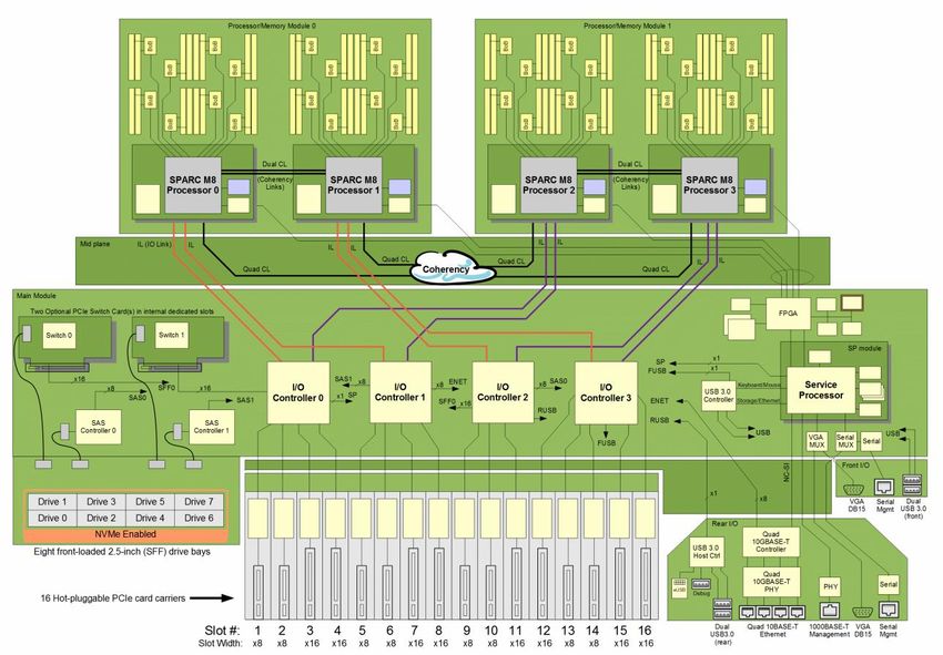
21 | ORACLE’S SPARC T8 AND SPARC M8 SERVER ARCHITECTUREFigure 12 provides a block-level diagram of the SPARC T8-4 server. Up to two specialized processor/memory modules each provide two SPARC M8 sockets and 32 DDR4 DIMM slots (16 DIMM slots per processor socket, 64 DIMM slots per server). A midplane redundantly connects the coherency links of each processor socket to a processor socket on the other processor/memory module. Redundant ILs connect each processor socket to two of the four I/O controllers. Four I/O controllers furnish PCIe root complexes for all PCIe slots in the system, providing substantial I/O capabilities. SAS HDDs, SAS SSDs, or NVMe SSDs can be installed in any of the drive bays. The optional NVMe PCIe switch cards do not consume any of the system’s hot-pluggable PCIe carrier slots at the rear of the chassis, leaving more capacity for additional I/O devices. Figure 12. SPARC T8-4 servers feature two dual-processor/memory modules and four I/O controllers ASICs. 22 | ORACLE’S SPARC T8 AND SPARC M8 SERVER ARCHITECTURE
You can also read