Owner's and Safety Manual - for Brush Cutter/String Trimmer
←
→
Page content transcription
If your browser does not render page correctly, please read the page content below
Owner’s and Safety Manual
                                            for Brush Cutter/String Trimmer

                                            Manuel d’emploi et de sécurité
                                            de la Débroussailleuse Thermique

                                            Manual de empleo y de seguridad
                                            para Desbrozadora

                                 EM2600U                                                                    EM2600L

Important:
Read this instruction manual carefully before putting the brush cutter/string trimmer into operation and strictly observe the safety regulations!
Preserve instruction manual carefully!
Important :
Lisez attentivement ce manuel d’instructions avant de vous servir de la débroussailleuse thermique pour la première fois, et respectez à la
lettre les consignes de sécurité!
Conservez précieusement ce manuel d’instructions!
Importante:
Lea esta manual de instrucciones con atención antes de utilizar la desbrozadora y ¡observe estrictamente las regulaciones de seguridad!
¡Conserve cuidadosamente su manual de instrucciones!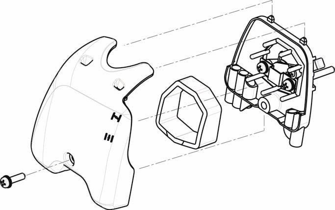
English

Thank you for purchasing this MAKITA brush cutter/string trimmer. MAKITA        Table of Contents                                                         Page
brush cutters/string trimmers are developed as a product of our many years of   Symbols ........................................................................ 2
knowledge, experience, and a detailed development programme.                    Safety instructions......................................................... 3
Please read this booklet thoroughly to ensure you gain the best possible        Technical data............................................................... 7
performance and outstanding results that your MAKITA brush cutter/string        Names of parts.............................................................. 8
trimmer can provide.                                                            Mounting the handle ..................................................... 9
                                                                                Mounting the protector ................................................ 10
                                                                                Mounting the cutter blade/nylon cutting head ............. 11
                                                                                Fuel/Refuelling ............................................................ 12
                                                                                Correct handling.......................................................... 13
                                                                                Important operating points/stopping the cutter/
                                                                                trimmer ........................................................................ 13
                                                                                Resharpening the cutting tool ..................................... 15
                                                                                Servicing instructions .................................................. 17
                                                                                Storage ....................................................................... 19

 Symbols
You need to note the following symbols when reading the instructions manual.

                                                                                    Wear eye and ear protection
                     Read instruction Manual
                                                                                    (for string trimmer only)

                                                                                    Wear protective helmet, eye and ear protection
                     Take Particular care and Attention
                                                                                    (for brush cutter only)

                                                                                    Do not use metal blades
                     Forbidden
                                                                                    (for string trimmer only)

                     Keep your distance                                             Maximum permissible tool speed

                     Flying object hazard                                           Hot surfaces - Burns to fingers or hands

                     No Smoking                                                     Fuel and oil mixture

                     No open flames                                                 Engine-Manual start

                     Protective gloves must be worn                                 Emergency stop

                     Kickback                                                       First Aid

                     Keep the area of operation clear of all
                                                                                    ON/START
                     persons and animals

                     Wear sturdy boots with nonslip soles. Steel-
                                                                                    OFF/STOP
                     toed safety boots are recommended.

                                                                                    START

                                                                      2
Safety instructions
General Instructions
– To ensure correct operation, make sure that you read and fully understand
this instruction manual to familiarise yourself with how to use the brush cutter/
string trimmer. Using this equipment without understanding how to operate it
correctly may result in serious injury to yourself or others.
– Only lend the brush cutter/string trimmer to people who have proved
experienced with brush cutter/string trimmers. Always lend them this
instruction manual at the same time.
– If this is your first time using an engine powered cutter, consult your dealer for
basic instructions.
– Children and young persons aged under 18 years must not be allowed to
operate the brush cutter/string trimmer. Persons over the age of 16 years may
use the device for training purposes, only whilst under supervision of a
qualified trainer.
– Use brush cutter/string trimmers with the utmost care and attention.
– Only operate the brush cutter/string trimmer if you are in good physical
condition. Perform all work calmly and carefully. Users must accept
responsibility for those around them.
– Never use the brush cutter/string trimmer after consumption of alcohol or
medicines, or if you are feeling tired or ill.
WARNING: This machine produces an electromagnetic field during operation.
This field may under some circumstances interfere with active or passive
medical implants. To reduce the risk of serious or fatal injury, we recommend
persons with medical implants to consult their physician and the medical implant
manufacturer before operating this machine.
Intended use of the equipment
– The brush cutter/string trimmer is only intended for cutting grass, weeds, bush
and other such undergrowth, and should not be used for any other purpose
such as edging or hedge cutting as this may cause injury.
Personal protective equipment (1)
– Always wear clothing that is both functional and appropriate to your work, i.e.
tight-fitting, but not so tight as to cause uncomfortable movement. Do not wear
either jewelry or clothing which could become entangled with bushes or
shrubs.
– In order to avoid head, eye, hand, or foot injuries, as well as to protect your
hearing during operation, the following protective equipment and protective (2)
clothing must be used while using the brush cutter/string trimmer.
– Always wear a helmet where there is a risk of falling objects. The protective (3)
helmet (1) is to be checked at regular intervals for damage and is to be
replaced at the latest after 5 years. Use only approved protective helmets.
– The visor (2) of the helmet (or alternatively goggles) protects the face from
flying debris and stones. During operation of the brush cutter/string trimmer,
always wear goggles or a visor to prevent eye injuries.
– Wear adequate noise protection equipment to avoid hearing impairment (ear (4)
muffs (3), ear plugs etc.).
– Work overalls (4) protect against flying stones and debris.
We strongly recommend that you wear work overalls.
– Special gloves (5) made of thick leather are part of the prescribed equipment
and must always be worn during operation of the brush cutter/string trimmer.
– When using the brush cutter/string trimmer, always wear sturdy shoes (6) with
a non-slip sole. Such shoes protect against injuries and ensure good footing.
(5) (6)
Residual risks
– Even when the machine is used as prescribed it is not possible to eliminate all
residual risk factors. The following hazards may arise in connection with the
machine’s construction and design:
1. Damage to lungs if an effective dust mask is not worn. Diagram
2. Damage to hearing if effective hearing protection is not worn.
3. Damages to health resulting from vibration emission if the machine is being
used over longer period of time or not adequately managed and properly
maintained.
Starting the brush cutter
– Make sure that there are no children or other people within a working range of 15 meters
15 meters (50ft), also pay attention to any animals in the working vicinity.
– Before use, always check that the brush cutter/string trimmer is safe for
operation:
Check that the cutting tool is secure, that the control lever can be operated
easily, and that the control lever lock is functioning correctly.
– Rotation of the cutting tool during idling is prohibited. Check with your dealer if
you think the equipment may need adjusting. Check to make sure that the
handles are clean and dry, and that the start/stop switch is functioning
correctly.
3– Start the brush cutter/string trimmer only in accordance with the instructions.
Do not use any other methods to start the engine!
– Only use the brush cutter/string trimmer and tools for the specified purposes.
– Only start the brush cutter/string trimmer engine after the equipment is fully
assembled. Do not operate the equipment until all of the appropriate
accessories are attached!
– Before starting, make sure that the cutting tool is not in contact with hard objects
such as branches, stones etc. as the cutting tool will rotate when starting.
– Switch off the engine immediately if any type of engine problem occurs.
– Should the cutting tool hit stones or other hard objects, immediately switch off
the engine and inspect the cutting tool.
– Inspect the cutting tool at short regular intervals for damage (inspect for
hairline cracks using the tapping test).
– Only operate the brush cutter/string trimmer after attaching and adjusting the
shoulder strap to the correct length. The shoulder strap must be adjusted to
the user’s size and fastened to prevent fatigue during operation of the
equipment. Never hold the cutter with one hand during operation.
– During operation, always hold the brush cutter/string trimmer with both hands.
Always ensure you are on safe footing.
– Operate the brush cutter/string trimmer in such a manner as to avoid
inhalation of the exhaust gases. Never run the engine in an enclosed space
such as inside a room (risk of gas poisoning). Carbon monoxide is an odorless
gas.
– Always switch off the engine when resting, or if you intend to leave the brush
cutter/string trimmer unattended, and place it in a safe location to prevent
injury to other people and damage to the equipment.
– Never put the hot brush cutter/string trimmer onto dry grass or onto any other
combustible materials.
– The cutting tool must always be equipped with the appropriate guard.
Never run the cutter without this guard!
– All protective installations and guards supplied with the equipment must be
used during operation. • Resting
• Transport
– Never operate the engine if the exhaust muffler is faulty.
• Refuelling
– Shut off the engine during transport. • Maintenance
– When transporting the equipment, always attach the cover to the cutting • Tool Replacement
blade.
– Ensure the brush cutter/string trimmer is positioned safely during transport to
avoid fuel leakage.
– When transporting the brush cutter/string trimmer, ensure the fuel tank is
completely empty.
– When unloading the brush cutter/string trimmer from a truck or other such
vehicle, never drop the engine to the ground, as doing so may severely
damage the fuel tank.
– Unless in an emergency, never drop or cast the brush cutter/string trimmer to
the ground as doing so may severely damage the brush cutter/string trimmer.
– Always lift the entire equipment from the ground when moving it. Dragging the
equipment on its fuel tank is extremely dangerous and may cause fuel to leak,
which may cause fire.
– If the equipment gets heavy impact or fall, check the condition before
continuing work. Check the fuel system for fuel leakage and the controls and
safety devices for malfunction. If there is any damage or doubt, ask our
authorized service center for the inspection and repair.
Refuelling
– Shut off the engine during refuelling, keep away from open flames and do not
smoke during refuelling.
– Ensure mineral oil products do not come into contact with skin. Do not inhale
the fuel vapor. Always wear protective gloves during refuelling. Change and
clean protective clothing at regular intervals.
– To prevent soil contamination (environmental protection), make sure you do
not spill fuel or oil on the ground. If you do spill fuel, clean the brush cutter/
string trimmer immediately.
– Make sure fuel does not come into contact with your clothing. If fuel does
come into contact with your clothing, change your clothing immediately to
prevent fire.
– Inspect the fuel cap at regular intervals to make sure that it can be securely
fastened and does not leak.
– Carefully tighten the fuel tank cap. Once refuelling is complete, move to a
location at least 3 meters away from where you refuelled before starting the
engine.
– Never refuel in an enclosed space such as inside a room. Doing so may cause
an explosion due to the accumulation of fuel vapor at ground level.
4– Only transport and store fuel in approved containers. Make sure stored fuel is
not accessible to children.
Method of operation
– Only use the brush cutter/string trimmer in good light and visibility. During the
winter season, beware of slippery or wet areas such as icy or snow-covered
areas (risk of slipping). Always ensure you are on safe footing.
– Never cut above waist height.
– Never stand on a ladder while using the brush cutter/string trimmer.
– Never climb up into trees to use with the brush cutter/string trimmer.
– Never work on unstable surfaces.
– Remove sand, stones, nails etc. found within the working range.
Foreign objects may damage the cutting tool and can cause dangerous kick-
backs.
– Before starting to cut, make sure the cutting tool has reached full working
speed.
– If grass or branches get caught between the cutting tool and guard, always
stop the engine before cleaning. Otherwise unintentional blade rotation may
cause serious injury.
– Take a rest to prevent loss of control caused by fatigue. We recommend to
take a 10 to 20-minute rest every hour.
Kickback (blade thrust)
Caution:
– When operating the brush cutter, uncontrolled kickbacks may occur. Kickback
– Kickbacks occur frequently when attempting to cut with the 12 to 2 o’clock
section of the blade.
– Never apply the 12 to 2 o’clock section of the brush cutter blade.
– Never apply this section of the brush cutter blade to solid objects, such as
bushes or trees etc. that have a diameter greater than 3 cm. Doing so will
cause the brush cutter to deflect with a large amount of force, which is
extremely dangerous and may cause injury.
Diagram
Kickback prevention
To avoid kickbacks, remember the following:
– Using the 12 to 2 o’clock section of the blade is extremely hazardous,
especially when using metal cutting tools.
– Cutting operations using the 11 to 12 o’clock section and 2 to 5 o’clock section
of the blade must only be performed by trained and experienced operators,
and then only at their own risk.
The optimum cutting section for easy cutting with almost no kickback is
between the 8 to 11 o’clock section of the blade.
Diagram
Cutting Tools
– Use an applicable cutting tool for the job in hand.
Nylon cutting heads (string trimmer heads) are suitable for trimming lawn
grass.
Metal blades are suitable for cutting weeds, high grasses, bushes, shrubs,
underwood, thicket, and the like.
Never use other blades including metal multi-piece pivoting chains and flail
blades. Otherwise serious injury may result.
– When using metal blades, avoid “kickback” and always prepare for an
accidental kickback. See the section “Kickback” and “Kickback prevention”.
Maintenance instructions
– Have your equipment serviced by our authorized service center, always using
only genuine replacement parts. Incorrect repair and poor maintenance can
shorten the life of the equipment and increase the risk of accidents.
– Always check the condition of the cutter, in particular the cutter protective
devices and shoulder strap, before commencing work. Particular attention
should also be paid to the cutting blades, which must be correctly sharpened.
– Turn off the engine and remove the spark plug connector when replacing or
sharpening cutting tools, and also when cleaning the cutter or cutting tool.
5Never straighten or weld damaged cutting tools.
– Operate the brush cutter/string trimmer with as little noise and contamination
as possible. In particular, check that the carburetor is set correctly.
– Clean the brush cutter/string trimmer at regular intervals and check that all
screws and nuts are well tightened.
– Never service or store the brush cutter/string trimmer in the vicinity of naked
flames.
– Always store the brush cutter/string trimmer in locked rooms and with an
emptied fuel tank.
– When cleaning, servicing and storing the equipment, always attach the cover
to the cutting blade.
Observe the relevant accident prevention instructions issued by the relevant
trade associations and insurance companies.
Do not perform any modifications on the brush cutter/string trimmer, as doing so
will endanger your safety.
The performance of maintenance or repair work by the user is limited to those
activities described in the instruction manual. All other work is to be done by an
Authorized Service Agent. Use only genuine spare parts and accessories
released and supplied by MAKITA.
Using non-approved accessories and tools will cause an increased risk of
accidents.
MAKITA will not accept any liability for accidents or damage caused by the use
of non-approved cutting tools, fixing devices of cutting tools, or accessories.
First Aid
In case of accident, make sure that a first-aid box is available in the vicinity of the
cutting operations. Immediately replace any item taken from the first aid box.
When asking for help, please give the following information:
– Place of the accident
– What happened
– Number of injured persons
– Kind of injuries
– Your name
Vibration
– People with poor circulation who are exposed to excessive vibration may
experience injury to blood vessels or the nervous system. Vibration may
cause the following symptoms to occur in the fingers, hands or wrists: “Falling
asleep” (numbness), tingling, pain, stabbing sensation, alteration of skin color
or of the skin. If any of these symptoms occur, see a physician!
– To reduce the risk of “white finger disease”, keep your hands warm during
operation and well maintain the equipment and accessories.
6Technical data
EM2600U EM2600L
Model
U handle Loop handle
1,770 x 610 x 410 mm 1,770 x 330 x 185mm
Dimensions: length x width x height (without cutting blade)
(69-3/4 x 24 x 16-1/8”) (69-3/4 x 13 x 7-1/4”)
Net Weight 5 kg (11 lbs) 5 kg (11 lbs)
Engine displacement 25.7 cm3 (1.57 cu. in.)
Maximum engine performance 0.83 kW
Maximum rotational frequency of the spindle 8,800/min
Single piece metal blade φ230 mm (9”)
Cutting attachment
String trimmer head φ430 mm (17”)
Idling speed 3,000/min
Clutch engagement speed 4,100/min
Gear ratio 14/19
Mixed gas
Fuel
Gasoline: Two-stroke Engine Oil = 50:1
Volume (fuel tank) 0.6 L (36.6 cu. in.)
Carburetor WALBRO WYC
Spark plug NGK BPMR7A
Electrode gap 0.6 - 0.7 mm (0.024 - 0.028”)
(For Canada) NOTE: This spark ignition system complies with the Canadian standard ICES-002.
7Names of parts
EM2600U
U Handle Type
EM2600L
Loop Handle Type
(3)
(7) (19)
Names of parts
1 Fuel Tank
2 Rewind Starter
3 Air Cleaner
4 I-Stop Switch (on/off)/Start-Stop Switch
5 Spark Plug
(21)
6 Exhaust Muffler
7 Clutch Case
(1) 8 Rear Grip
9 Hanger
10 Handle
11 Control Lever
12 Control Cable
13 Shaft
14 Protector (Cutting tool guard)
15 Gear Case
16 Handle Holder
17 Cutter Blade
18 Nylon Cutting Head
19 Fuel Filler Cap
20 Starter Knob
21 Primer Pump
22 Choke Lever
8Mounting the handle
CAUTION: Before doing any work on the brush cutter, always stop the engine
and disconnect the spark plug connector from the spark plug.
Always wear protective gloves!
CAUTION: Ensure you have reassembled the brush cutter completely before
starting it.
For U handle models
– Place the two handles onto the handle holder. The control lever must come
right side when you look towards the cutting tool.
– Fit the handle ends to the groove on the handle holder and fit the clamp on
them. Loosely tighten them with four bolts for adjustment.
– Adjust handles’ angle, and then tighten all bolts evenly by a hex wrench.
L
R
EM2600U
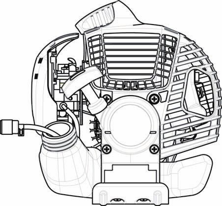
– Place the throttle cable (1) to the control lever side of the shaft. And then wrap
them with the waist pad (2).
(2)
(1)
EM2600U
– Insert the throttle cable (1) into the clamping slot (3) of the handle holder.
– Make sure the throttle cable is positioned as shown.
– Operate the control lever and make sure it moves smoothly.
(3)
(1)
EM2600U
CAUTION: Do not position the throttle cable as shown. Otherwise curved cable
may cause high idle speed, and uncontrollable blade may cause
personal injury.
EM2600U
9For loop handle model
– Put the thread (1) on handle holder into the location hole (2) on tube. (4)
(2)
– Fix the assistant handle (3) onto the barrier.
– Tighten the 4 bolts (4) M5 x 30.
(1)
(3)
Engine Engine
EM2600L
Mounting the protector
To meet the applicable safety standards, you must only use the tool/protector
combinations indicated in the table.
Always use genuine MAKITA cutter blades/nylon cutting head.
– The cutter blade must be well polished, and free of cracks or breakages. If the
cutter blade hits against a stone during operation, stop the engine and check
the blade immediately.
– Polish or replace the cutter blade every three hours of operation.
– If the nylon cutting head hits against a stone during operation, stop the engine
and check the nylon cutting head immediately.
Star Blade Protector for metal blades Nylon cutting head Protector for cord cutter
CAUTION: The appropriate protectors must always be installed for your own
safety and in order to comply with accident-prevention regulations.
Operation of the equipment without the guard installed is prohibited.
– Fix the protector (1) to the clamp (3) with two M6 x 30 bolts (2).
(2)
(3)
(1)
– When using the nylon cutting head, fit the protector (5) into the protector (1),
and tighten them with two screws (4).
10Mounting the cutter blade/nylon cutting head
The cutter blade or nylon cutting head can be replaced easily by first turning the
equipment upside down.
– Insert the hex wrench through the hole in the gear case and rotate the receiver
washer (3) until it is locked with the hex wrench. (1) (2)
– Loosen the nut/spring washer (1) (left-hand thread) with the socket wrench,
and remove the nut/spring washer (1) and clamp washer (2).
(3)
With the hex wrench still in place
– Mount the cutter blade onto the shaft so that the guide of the receiver washer
(3) fits in the arbor hole in the cutter blade. Install the clamp washer (2) and Tighten
secure the cutter blade with the nut/spring washer (1). Loosen
[Tightening torque: 13 - 23 N-m]
NOTE: Always wear gloves when handling the cutter blade.
NOTE: The cutter blade-fastening nut (with spring washer) is a consumable
part. If there appears any wear or deformation on the spring washer,
replace the nut.
Hex wrench
NOTE: The clamp washer (2), and nut/spring washer (1) are not necessary for
mounting the nylon cutting head. The nylon head should go on top of the
receiver washer (3).
– Screw the nylon cutting head onto the shaft.
Tighten
Loosen
Hex wrench
– Make sure that the blade rotates counterclockwise.
Rotation
11Fuel/Refuelling
Handling fuel
Utmost care is required when handling fuel. Fuel may contain substances similar
to solvents. Refuel either in a well ventilated room or outdoors. Do not inhale fuel
vapors, and avoid any contact of fuel or oil with your skin.
Mineral oil products degrease your skin. Prolonged skin contact with these
products will cause your skin to become extremely dry, which may result in
various kinds of skin disease. In addition, allergic reactions may occur.
Eyes can be irritated by contact with oil. If oil comes into your eyes, immediately
wash them with clear water. If your eyes are still irritated, see a doctor
immediately.
Observe the Safety Instructions on page 3.
Fuel and oil mixture
The brush cutter engine is a high-efficiency two-stroke engine. It runs on a
mixture of fuel and two-stroke engine oil. The engine is designed for unleaded
regular fuel with a min. octane value of 91 RON.
To obtain optimum engine performance and to protect your health and the
environment, use only unleaded fuel!
To lubricate the engine, add two-stroke engine oil (quality grade: JASO FC or
ISO EGD) to the fuel. The engine has been designed to use the specified two-
stroke engine oil at mixture ratio of 50:1 to protect the environment.
Additionally, long service life accompanied by reliable operation and minimum
emissions are guaranteed through the use of this mixture ratio. Reliable
functioning of the brush cutter cannot be guaranteed unless this mixture ratio of
50:1 (specified 2-stroke engine oil) is strictly observed.
Correct mixture ratio:
Gasoline 50:1 25:1
Gasoline: Specified two-stroke engine oil = 50 : 1 or
Gasoline: Other manufacturer’s two-stroke engine oil = 25 : 1 recommended
NOTE: To prepare the fuel-oil mixture, first mix the entire oil quantity with half of
the fuel required, then add the remaining fuel. Thoroughly shake the +
mixture before pouring it into the brush cutter tank. To ensure safe
operation, do not add more engine oil than the specified amount. Doing
so will only result in a higher production of combustion residues which
pollute the environment and clog the exhaust channel in the cylinder as 1,000 cm3 (1 liter) 20 cm3 40 cm3
well as the muffler. In addition, the fuel consumption will rise and the 5,000 cm3 (5 liter) 100 cm3 200 cm3
performance will decrease. 10,000 cm3 (10 liter) 200 cm3 400 cm3
Refuelling
The engine must be switched off.
– Thoroughly clean the area around the fuel filler cap (2) to prevent dirt from
getting into the fuel tank (1).
– Unscrew the fuel filler cap (2) and fill the tank with fuel.
– Tightly screw on the fuel filler cap (2).
– Clean the screw fuel filler cap (2) and tank after refueling.
Storage of Fuel
Fuel cannot be stored for an unlimited period of time.
Purchase only the quantity required for a 4-week operating period. Only use
approved fuel storage containers.
12Correct handling
Attachment of shoulder strap
– Adjust the strap length so that the cutter blade is kept parallel with the ground.
Detachment
– In case of emergency, push the notches (1) at both sides, and detach the
equipment.
Be extremely careful to maintain control of the equipment at this time. Do not
allow the equipment to be deflected toward you or anyone in your vicinity.
WARNING: Failure to maintain complete control of the machine at all could
result in serious injury or DEATH. (1)
Note: In some countries, shoulder strap does not have this detachment function.
Hanger
Important operating points/stopping the cutter/trimmer
Observe the applicable accident prevention regulations.
Starting
Move at least 3 m away from the area where you refuelled the equipment. Place the brush cutter on a clean piece of ground taking care that the
cutting tool does not come into contact with the ground or any other objects.
WARNING: Pay attention that the cutting tool rotates immediately after the
engine starts. (1)
(4)
Cold start for U handle models
– Set the I-Stop Switch (on/off) (1) as illustrated.
– Grasp the handle (hand pressure activates the safety lock-off lever (2)).
– Press the throttle lever (3) and hold it down. (3)
(2)
– Press the lock button (4) and release the control lever, and then release the
lock button (the lock button holds the throttle lever in the start-up position).
EM2600U
Cold start for loop handle models
– Set the Start-Stop Switch (1) to start position as illustrated.
(2)
– Grasp the handle (hand pressure activates the safety lock-off lever (2)).
– Press the throttle lever (3) and hold it down.
– Set the Start-Stop Switch (1) to start position and release the control lever,
and then release the Start-Stop Switch (the Start-Stop Switch holds the
throttle lever in the start-up position).
(3)
(1) EM2600L
13Warm start for U handle models
– Set the I-Stop Switch (on/off) (1) as illustrated.
EM2600U
Warm start for loop handle models
– Set the Start-Stop Switch (1) to neutral position as illustrated.
EM2600L
– First, place the equipment on the ground. (6)
– Gently press the primer pump (5) repeatedly (7-10 times) until fuel comes into
the primer pump. CLOSE
– Close the choke lever (6).
Choke opening:
• Fully closed in cold temperatures or when the engine is cold
• Fully or half open for restart while the engine is still warm
(5)
– Firmly hold the clutch case with your left hand, as illustrated.
– Slowly pull the starter grip until you feel resistance, and then continue to pull
sharply.
– Do not pull out the starter rope to its full extent, and do not allow the starter
handle to retract by itself. Maintain control of the starter rope and ensure it
retracts slowly.
– Repeat the starting operation until you hear the engine’s initial ignitions.
– Depress the choke lever (6) ( ) and pull the starter rope again until the
engine starts.
– As soon as the engine starts, immediately tap and release the throttle, to
release the half-throttle lock and allow the engine to idle.
– Run the engine for approximately one minute at a moderate speed before
applying full throttle.
OPEN
(6)
(5)
NOTE: – If you pull the starter handle repeatedly when the choke lever is in the at “ ” position, the engine will not start easily due to excessive
fuel intake.
– If excessive fuel intake occurs, remove the spark plug and pull the starter handle slowly to remove excess fuel. Also, dry the electrode
section of the spark plug.
14Caution during operation:
If the throttle lever is opened fully during a no-load operation, the engine revolutions increase over 10,000 min-1. Never operate the engine at a
higher speed than required, and keep the revolutions at an approximate speed of 6,000 - 8,000 min-1.
CAUTION: Always reduce the engine revolutions when the equipment is not being used for work.
Operating the equipment at high revolutions when not being used for work will shorten the lifespan of the equipment.
Stopping
– Release the throttle lever (3) fully, and when the engine rpm has lowered,
push the I-Stop Switch (on/off)/Start-Stop Switch (1) to “STOP” position to
stop the engine.
– Be aware that the cutting head may not stop immediately, and always allow it
to slow down and stop fully by itself.
EM2600U
EM2600L
Resharpening the cutting tool
CAUTION: The cutting tools listed below must only be resharpened by an
authorized facility. Manual resharpening will result in imbalances of
the cutting tool, which will cause vibrations and damage to the
equipment.
– cutter blade (star blade (4 teeth))
A professional resharpening and balancing service is provided by Authorized
Service Agents.
NOTE: To increase the service life of the cutter blade (star blade) the blade may
be turned over to allow both cutting edges to wear.
15NYLON CUTTING HEAD
Most effective cutting area
The nylon cutting head is a dual line trimmer head that has bump & feed
mechanism.
The nylon cutting head feeds out the nylon cord after tapping the trimmer head
on the ground.
Operation
– The most effective cutting area is shown by the shaded area.
– To feed the nylon cord, increase the nylon cutting head speed to approx.
6,000 min-1 and tap the nylon cutting head lightly on the ground.
– If the nylon cutting head does not feed out by tapping, rewind/replace the
nylon cord by following the procedures described under “Replacing the nylon
cord.”
Replacing the nylon cord
– Stop the engine.
– Press the housing latches inward to lift off the cover, then remove the spool. Cover
Latches
Press Press
– Hook the center of new nylon cord into the notch in the center of the spool,
with one end of the cord extending about 80 mm (3-1/8”) more than the other. Spool 80 mm (3-1/8”)
Then wind both ends firmly around the spool in the direction of the head
rotation (left-hand direction indicated by LH and right-hand direction by RH on
the side of the spool).
Spool
For left hand
rotation
– Wind all but about 150 mm (6”) of the cords around the spool, leaving the ends
temporarily hooked through the notch on the side of the spool.
150 mm (6”)
Notches
16– Feed the cords through the eyelets to come out of the housing.
Mount the washer, spring, and spool in the housing.
Eyelet
– Align the hooks on the the cover and the housing.
Then push cover firmly onto the housing to secure it.
Cover
Hook Hook
Eyelet
Servicing instructions
Servicing instructions
CAUTION: Before performing any type of maintenance work on the brush
cutter, always switch off the motor and detach the plug cap from the
spark plug (see “checking the spark plug”).
Always wear protective gloves.
CAUTION: Never remove the recoil starter yourself. Doing so may cause an
accident. This procedure should only be performed by an Authorized
Service Agent.
To ensure a long service life and to avoid any damage to the equipment, perform the following maintenance operations regularly.
Daily inspection and maintenance
– Before operation, check the equipment for loose screws or missing parts. Pay particular attention to the tightness of the cutter blade or nylon
cutting head.
– Before operation, always check to make sure that the cooling air passage and cylinder fins are not clogged.
Clean them if necessary.
– Perform the following maintenance operations daily after use:
• Clean the brush cutter externally and inspect it for damage.
• Clean the air filter. When working under extremely dusty conditions, clean the filter several times a day.
• Check the blade or the nylon cutting head for damage and make sure it is firmly mounted.
• Check that there is sufficient difference between the idling and operating speeds to ensure the cutting tool is at a standstill while the engine
is idling (if necessary, reduce the idling speed).
If the cutting tool continues to rotate during engine idling, consult your nearest Authorized Service Agent.
– Check that the I-Stop Switch (on/off)/Start-Stop Switch, the lock-off lever, the control lever, and the lock button are all functioning correctly.
Cleaning the air cleaner (filter)
(4)
– Turn the choke lever (4) to the fully closed side, and keep the carburetor away
from any dust or dirt.
– Remove the screw (1).
(1)
– Remove the air cleaner cover (3).
– Remove the sponge element (2), wash it in lukewarm water and dry it
completely.
– After cleaning, put back the air cleaner cover (3) and fasten it with screw (1).
NOTE: If there is excessive dust or dirt adhering to the air cleaner, clean it every (2)
day. A clogged air cleaner may make it difficult or impossible to start the (3)
engine or increase the engine rotational speed.
17Checking the spark plug
– Only use the supplied universal wrench to remove or to install the spark plug.
– The gap between the two electrodes of the spark plug should be 0.6-0.7 mm
(0.024”-0.028”). If the gap is too wide or too narrow, adjust it. If the spark plug
is clogged with carbon or dirty, clean it thoroughly or replace it.
CAUTION: Never touch the spark plug connector while the engine is running
(danger of high voltage electric shock).
0.6 mm-0.7 mm
(0.024”-0.028”)
Supply of grease to gear case
Grease hole
– Supply grease (Shell Alvania 2 or equivalent) to the gear case through the
grease hole every 30 hours. (Genuine MAKITA grease may be purchased
from your MAKITA dealer.)
Suction head in the fuel tank
– The fuel filter (5) of the suction head is used to supply the fuel required by the
carburetor.
– Visually inspect the fuel filter periodically. To inspect the filter, open the fuel (5)
filler cap, use a wire hook and pull out the suction head through the tank
opening. Replace the filter if it has hardened, become particularly dirty, or
clogged.
– Insufficient fuel supply may result in the maximum permissible speed being
exceeded. Therefore, the fuel filter must be replaced at least quarterly to
ensure satisfactory fuel supply to the carburetor.
Any other maintenance or adjustment work that is not described in this manual must only be performed by Authorized Service Agents.
18Storage
– When storing the equipment for a long period of time, drain all the fuel from
the fuel tank and carburetor. To do this, simple drain all of the fuel from the
fuel tank. Dispose of the drained fuel in accordance with local applicable laws.
– Remove the spark plug and add a few drops of oil into the spark plug hole.
Then, pull the starter gently so that oil coats the inside of the engine, then
tighten the spark plug.
– Clean any dirt or dust from the cutter blade and outside of the engine, and Drain fuel Humidity
wipe them with a oil-immersed cloth. Store the equipment in a dry place.
Maintenance schedule
General Visual inspection for damage and tightness
Engine assembly, screws and nuts
Check for general condition and security
After each refuelling Control lever Functional check
I-Stop Switch (on/off)/Start-Stop Switch Functional check
Daily Air filter To be cleaned
Cooling air duct To be cleaned
Cutting tool Check for damage and sharpness
Idling speed Inspection (cutting tool must not move)
Weekly Spark plug Inspection, replace if necessary
Muffler Inspect, and clean the opening if necessary
Quarterly Suction head To be replaced
Fuel tank To be cleaned
Shutting down procedure Fuel tank Empty fuel tank
Carburetor Operate until engine runs out of fuel
Troubleshooting
Fault System Observation Cause
Engine doesn’t start, or is Ignition system Ignition spark O.K. Fault in fuel supply or compression system, mechanical
difficult to start defect
No ignition spark I-Stop Switch (on/off)/Start-Stop Switch operated, wiring
fault or short circuit, spark plug or connector defective,
ignition module faulty
Fuel supply Fuel tank filled Incorrect choke position, carburetor defective, fuel
supply line bent or blocked, fuel dirty
Compression No compression when Cylinder bottom gasket defective, crankshaft seals
pulled over damaged, cylinder or piston rings defective or improper
sealing of spark plug
Mechanical fault Starter not engaging Broken starter spring, broken parts inside the engine
Warm start problems Tank filled. Ignition Carburetor contaminated, must be cleaned
spark O.K.
Engine starts but dies Fuel supply Tank filled Incorrect idling adjustment, carburetor contaminated
Fuel tank vent defective, fuel supply line interrupted,
cable or I-Stop Switch (on/off)/Start-Stop Switch faulty
Insufficient performance Several systems Engine idling poor Air filter contaminated, carburetor contaminated, muffler
may simultaneously clogged, exhaust duct in the cylinder clogged
be affected
19EMISSION COMPLIANCE PERIOD
For handheld engine: The Emissions
Compliance Period referred to on the Emissions
Compliance label indicates the number of operating hours for which the engine has been shown to meet Federal emission
requirements.
Category C=50 hours, B=125 hours, and A=300 hours.
AIR INDEX
An Air Index Information hang tag was supplied to this engine in accordance with the emission regulations of the California Air
Resources Board.
The bar graph on the hang tag shows the emissions performance of this engine.
The bar graph can be used to compare the emissions performance with other available engine.
The lower the Air Index, the less pollution.
The following durability description is to provide you with information relating to the emission durability period of the engine.
Descriptive Term Applicable to Emissions Durability Period
Moderate – 50 hours (0-65 cc)
Intermediate – 125 hours (0-65 cc)
Extended – 300 hours (0-65 cc)
Notice: The Air Index Information hang tag must remain on the engine or on the equipment until it is sold to the ultimate
purchaser. Remove the hang tag before operating the engine.
20CALIFORNIA EMISSIONS CONTROL WARRANTY STATEMENT
YOUR WARRANTY RIGHTS AND OBLIGATIONS
The California Air Resources Board and Makita USA, Inc are pleased to explain the emissions control system’s warranty on your 2007 and
later small off-road engine. In California, new equipment that use small off-engines must be designed, built, and equipped to meet the State’s
stringent anti-smog standards. Makita USA, Inc must warrant the emissions control system on your small off-road engine for the period listed
below provided there has been no abuse, neglect or improper maintenance of your equipment.
Your emissions control system may include parts such as: carburetors or fuel injection system, ignition system, catalytic converters, fuel tanks,
valves, filters, clamps, connectors, and other associated components. Also, included may be hoses, belts, connectors, sensors, and other
emission-related assemblies.
Where a warrantable condition exists, Makita USA, Inc will repair your small off-road engine at no cost to you including diagnosis, parts and
labor.
MANUFACTURER’S WARRANTY COVERAGE:
This emissions control system is warranted for two years. If any emissions-related part on your equipment is defective, the part will be repaired
or replaced by Makita USA, Inc.
OWNER’S WARRANTY RESPONSIBILITIES:
• As the small off-road engine owner, you are responsible for performance of the required maintenance listed in your owner’s manual. Makita
USA, Inc recommends that you retain all receipts covering maintenance on your small off-road engine, but Makita USA, Inc cannot deny
warranty solely for the lack of receipts or your failure to ensure the performance of all scheduled maintenance.
• As the small off-road engine owner, you should however be aware that Makita USA, Inc may deny you warranty coverage if your small off-
road engine or a part has failed due to abuse, neglect, or improper maintenance or unapproved modifications.
• You are responsible for presenting your small off-road engine to a Makita Factory Service Center as soon as the problem exists. The
warranty repairs should be completed in a reasonable amount of time, not to exceed 30 days. If you have a question regarding your warranty
coverage, you should contact:
* For the nearest Makita service center, please visit www.makitatools.com
* For technical support or questions regarding operation of our tools and accessories call: 1-800-4-MAKITA
* Makita USA Inc. Corporate Office: 14930 Northam St. La Mirada, CA 90638-5753
DEFECTS WARRANTY REQUIREMENTS:
(a) The warranty period begins on the date the engine or equipment is delivered to an ultimate purchaser.
(b) General Emissions Warranty Coverage. Makita USA, Inc must warrant to the ultimate purchaser and each subsequent owner that the
engine or equipment is:
(1) Designed, built, and equipped so as to conform with all applicable regulations adopted by the Air Resources Board; and
(2) Free from defects in materials and workmanship that causes the failure of a warranted part for a period of two years.
(c) The warranty on emissions-related parts will be interpreted as follows:
(1) Any warranted part that is not scheduled for replacement as required maintenance in the written instructions required by subsection (d)
must be warranted for the warranty period defined in Subsection (b) (2). If any such part fails during the period of warranty coverage, it
must be repaired or replaced by the manufacturer according to Subsection (4) below. Any such part repaired or replaced under the
warranty must be warranted for the remaining warranty period.
(2) Any warranted part that is scheduled only for regular inspection in the written instructions required by subsection (d) must be warranted
for the warranty period defined in Subsection (b) (2). A statement in such written instructions to the effect of “repair or replace as
necessary” will not reduce the period of warranty coverage. Any such part repaired or replaced under warranty must be warranted for
the remaining warranty period.
(3) Any warranted part that is scheduled for replacement as required maintenance in the written instructions required by subsection (d)
must be warranted for the period of time prior to the first scheduled replacement point for that part. If the part fails prior to the first
scheduled replacement, the part must be repaired or replaced by the engine manufacturer according to Subsection (4) below. Any
such part repaired or replaced under warranty must be warranted for the remainder of the period prior to the first scheduled
replacement point for the part.
(4) Repair or replacement of any warranted part under the warranty must be performed at no charge to the owner at a warranty station.
(5) Notwithstanding the provisions of Subsection (4) above, warranty services or repairs must be provided at all manufacturer distribution
centers that are franchised to service the subject engines.
(6) The owner must not be charged for diagnostic labor that leads to the determination that a warranted part is in fact defective, provided
that such diagnostic work is performed at a warranty station.
(7) The manufacturer is liable for damages to other engine components proximately caused by a failure under warranty of any warranted
part.
(8) Throughout the emissions warranty period defined in Subsection (b) (2), the manufacturer must maintain a supply of warranted parts
sufficient to meet the expected demand for such parts.
(9) Any replacement part may be used in the performance of any warranty maintenance or repairs and must be provided without charge to
the owner. Such use will not reduce the warranty obligations of the manufacturer.
(10) Add-on or modified parts that are not exempted by the Air Resources Board may not be used. The use of any non-exempted add on or
modified parts will be grounds for disallowing a warranty claim. The manufacturer will not be liable to warrant failures of warranted
parts caused by the use of a non-exempted add-on or modified part.
(11) The manufacturer issuing the warranty shall provide any documents that describe that manufacturer’s warranty procedures or policies
within five working days of request by the Air Resources Board.
(d) Emission Warranty Parts List.
(1) Fuel Metering System
(i) Carburetor and internal parts
(ii) Fuel Filter
(iii) Fuel Tank.
21(2) Air Induction System
(i) Air cleaner plate (including choke system)
(ii) Air cleaner cover
(iii) Air cleaner element
(3) Ignition System
(i) Spark Plugs.
(ii) Magneto or electronic ignition system.
(iii) Spark advance/retard system.
(4) Miscellaneous Items Used in Above Systems
(i) Hoses, Sealing gaskets, belts, connectors, and assemblies.
Makita USA, Inc will furnish with each new engine written instructions for the maintenance and use of the engine by the owner.
(e) MAINTENANCE STATEMENTS
It is your responsibility to have all scheduled inspection and maintenance services performed at the times recommended in the 2007 and
later Owner’s Manual and to retain proof that inspection and maintenance services are performed at the times when recommended. Makita
USA, Inc will not deny a warranty claim solely because you have no record of maintenance; however, Makita USA, Inc may deny a warranty
claim if your failure to perform required maintenance resulted in the failure of warranted part. The proof, which you maintain, should be given
to each subsequent owner of the engine. You are responsible for performing the scheduled maintenance described below based on the
procedures specified in the 2007 and later Owner’s Manual. The scheduled maintenance below is based on the normal engine-operating
schedule.
PROCEDURE INTERVAL
1) Clean engine and check bolts and nuts. Retighten if : Every 8 hours (daily)
necessary.
2) Check and refill engine oil (4 stroke engine only) : Every 8 hours (refill daily up to upper limit)
3) Change engine oil (4 stroke engine only) : Initial 20 hours and every 50 hours afterward
4) Check clogging of cooling air passage and cylinder fins. : Every 8 hours (daily)
Remove and clean if necessary.
5) Clean air cleaner. : Every 8 hours (daily)
6) Check spark plug. Clean and adjust if necessary. : Every 8 hours (daily)
7) Check muffler exhaust outlet (or port). Clean if : Every 50 hours (monthly)
necessary.
8) Check fuel filter. If clogged, replace with new one. : Every 50 hours (monthly)
9) Adjust valve clearance, if applicable (4 stroke engine : Every 200 hours (yearly)
only).
10) Replace fuel lines. : Every 200 hours (yearly)
11) Clean and inspect the complete engine. Replace any : Every 200 hours
damaged or worn out parts.
12) Replace packings and gaskets with new ones. : Every reassembling
22FEDERAL EMISSION COMPONENT DEFECT WARRANTY
EMISSION COMPONENT DEFECT WARRANTY COVERAGE - This emission warranty is applicable in all States,
except the State of California
Makita U.S.A., Inc., (herein “Makita”) warrant to the initial retail purchaser and each subsequent owner, that this
utility equipment engine (herein “engine”) was designed, built, and equipped to conform at the time of initial sale to
all applicable regulations of the U.S. Environmental Protection Agency (EPA), and that the engine is free of defects
in materials and workmanship which would cause this engine to fall to conform with EPA regulations during its
warranty period.
For the components listed under PARTS COVERED, the dealer or service center authorized by Makita will, at no
cost to you, make the necessary diagnosis, repair, or replacement necessary to ensure that the engine complies
with applicable U.S. EPA regulations.
EMISSION COMPONENT DEFECT WARRANTY PERIOD
The warranty period for this engine begins on the date of sale to the initial purchaser and continues for a period of
2 years.
PARTS COVERED
Listed below are the parts covered by the Emission Component Defect Warranty. Some of the parts listed below
may require scheduled maintenance and are warranted up to the first scheduled replacement point for that part.
1) Fuel Metering System 3) Ignition System
(i) Carburetor and internal parts (i) Spark plug
(ii) Fuel filter, if applicable (ii) Flywheel Magneto
(iii) Throttle stopper, if applicable (iii) Ignition Coil
(iv) Choke System, if applicable
2) Air Induction System 4) Miscellaneous Items Used in Above Systems
(i) Air cleaner plate (i) Fuel hoses, clamps and sealing gaskets
(ii) Air cleaner case
(iii) Air cleaner element
5) Emission-related components for evaporative emission
(i) Fuel Tank
(ii) Fuel Cap
(iii) Fuel line
(iv) Fuel line fitting
(v) Clamps
23OBTAINING WARRANTY SERVICE
To obtain warranty service, take your engine to the nearest MAKITA Factory Service Center authorized by
MAKITA. Bring your sales receipts indicating date of purchase for this engine. The dealer or service center
authorized by Makita will perform the necessary repairs or adjustments within a reasonable amount of time and
furnish you with a copy of the repair order. All parts and accessories replaced under this warranty become the
property of Makita.
WHAT IS NOT COVERED
* Conditions resulting from tampering, misuse, improper adjustment (unless they were made by the dealer or
service center authorized by Makita during a warranty repair), alteration, accident, failure to use the
recommended fuel and oil, or not performing required maintenance services.
* The replacement parts used for required maintenance services.
* Consequential damages such as loss of time, inconvenience, loss of use of the engine of equipment, etc.
* Diagnosis and inspection charges that do not result in warranty-eligible service being performed.
* Any non-authorized replacement part, or malfunction of authorized parts due to use of non-authorized parts.
OWNER’S WARRANTY RESPONSIBILITIES
As the engine owner, you are responsible for the performance of the required maintenance listed in your owner’s
manual, Makita recommends that you retain all receipts covering maintenance on your engine, but Makita can not
deny warranty solely for the lack of receipts or for your failure to ensure the performance of all scheduled
maintenance.
As the engine owner, you should however be aware that the Makita may deny your warranty coverage if your
engine or a part has failed due to abuse, neglect, improper maintenance or unapproved modifications.
You are responsible for presenting your engine to the nearest dealer or service center authorized by Makita when
a problem exists.
If you have any questions regarding your warranty rights and responsibilities, you should contact the Followings:
* For the nearest Makita service center, please visit www.makitatools.com
* For technical support or questions regarding operation of our tools and accessories call: 1-800-4-MAKITA
* Makita USA Inc. Corporate Office: 14930 Northam St. La Mirada, CA 90638-5753
(For Canada)
* For the authorized service center nearest you please refer to the local yellow pages directory under “tools”, or
contact our customer service department Tel 1-800-263-3734 (Canada only), or visit our web site www.makita.ca
* Makita Canada Inc. Head Office & Plant: 1950 Forbes Street, Whitby, ON L1N7B7.
24THINGS YOU SHOULD KNOW ABOUT THE EMISSION CONTROL SYSTEM WARRANTY
MAINTENANCE AND REPAIRS
You are responsible for the proper use and maintenance of the engine. You should keep all receipts and
maintenance records covering the performance of regular maintenance in the event questions arise. These
receipts and maintenance records should be transferred to each subsequent owner of the engine. Makita reserves
the rights to deny warranty coverage if the engine has not been properly maintained. Warranty claims will not be
denied, however, solely because of the lack of required maintenance or failure to keep maintenance records.
MAINTENANCE, REPLACEMENT OR REPAIR OF EMISSION CONTROL DEVICES AND
SYSTEMS MAY BE PERFORMED BY ANY REPAIR ESTABLISHMENT OR INDIVIDUAL;
HOWEVER, WARRANTY REPAIRS MUST BE PERFORMED BY A DEALER OR SERVICE
CENTER AUTHORIZED BY Makita. THE USE OF PARTS THAT ARE NOT EQUIVALENT IN
PERFORMANCE AND DURABILITY TO AUTHORIZED PARTS MAY IMPAIR THE
EFFECTIVENESS OF THE EMISSION CONTROL SYSTEM AND MAY HAVE A BEARING ON
THE OUTCOME OF A WARRANTY CLAIM.
If other than the parts authorized by Makita are used for maintenance replacements or for the repair of components
affecting emission control, you should assure yourself that such parts are warranted by their manufacturer to be
equivalent to the parts authorized by Makita in their performance and durability.
HOW TO MAKE A CLAIM
All repairs qualifying under this limited warranty must be performed by a service dealer authorized by MAKITA.
In the event that any emission-related part is found to be defective during the warranty period, you shall notify
MAKITA at the following contacts and you will be advised of the appropriate warranty service dealer or
service providers where the warranty repair can be performed.
* For the nearest Makita service center, please visit www.makitatools.com
* For technical support or questions regarding operation of our tools and accessories call: 1-800-4-MAKITA
* Makita USA Inc. Corporate Office: 14930 Northam St. La Mirada, CA 90638-5753
(For Canada)
* For the authorized service center nearest you please refer to the local yellow pages directory under “tools”, or
contact our customer service department Tel 1-800-263-3734 (Canada only), or visit our web site www.makita.ca
* Makita Canada Inc. Head Office & Plant: 1950 Forbes Street, Whitby, ON L1N7B7.
25Français
Nous vous remercions d’avoir acheté cette débroussailleuse thermique Table des matières Page
MAKITA. Les débroussailleuses thermiques MAKITA sont développées comme Pictogrammes ............................................................. 26
le fruit de nos nombreuses années de connaissances, d’expérience et d’un Consignes de sécurité................................................. 27
programme de développement détaillé. Données techniques ................................................... 31
Veuillez lire attentivement cette brochure pour vous assurer d’obtenir la Noms des pièces......................................................... 32
meilleure performance possible et les résultats extraordinaires que peut vous Montage de la poignée ............................................... 33
fournir votre débroussailleuse thermique MAKITA. Montage du protecteur ................................................ 34
Montage de la lame de coupe/de la tête à fils nylon ... 35
Remplissage du réservoir d’essence .......................... 36
Bonne manipulation .................................................... 37
Points de fonctionnement importants/arrêt de la
débroussailleuse ......................................................... 37
Réaffûtage de l’outil de coupe..................................... 39
Instructions d’entretien ................................................ 41
Entreposage................................................................ 43
Pictogrammes
Vous remarquerez les pictogrammes suivants en lisant le manuel d’instructions.
Protections oculaire et auditive obligatoires
Lisez le manuel d’instructions
(uniquement pour la débroussailleuse thermique)
Casque de protection, protections oculaire et
Faites particulièrement attention auditive obligatoires
(uniquement pour la débroussailleuse thermique)
Ne pas utiliser de lames métalliques
Interdit
(uniquement pour la débroussailleuse thermique)
Gardez vos distances Vitesse d’outil maximale autorisée
Surfaces chaudes – Risques de brûlure aux doigts
Danger de projections
et aux mains
Défense de fumer Mélange d’essence et d’huile
Pas de flammes nues Démarrage manuel du moteur
Gants de protection obligatoires Arrêt d’urgence
Mouvement de recul Premiers soins
Zone de fonctionnement interdite aux
MARCHE/DÉMARRAGE
personnes et aux animaux
Portez des chaussures solides avec semelle
antidérapante. Il est conseillé de porter des ARRÊT/COUPURE MACHINE
chaussures avec embout de sécurité.
DÉMARRAGE
26You can also read