OWNER'S MANUAL - High Five Motorsports
←
→
Page content transcription
If your browser does not render page correctly, please read the page content below
OWNER’S MANUAL
Before using this product, please read the instructions carefully and keep it for reference.
CONTENTS                                              WARNING
                                                1. To prevent short circuit, please keep the
    1. Included in Box                            device away from water or wet places.
    2. Interface Introduction                   2. If water or any other liquid soak into the
    3. Software Introduction                      device, cut off the power immediately, and call
    4. Product Technology Data                    our service engineer of inspection, in case of
                                                   emergency.
    5. Troubleshoothing
                                                3. Users are not allowed to dismoun the device,
                                                   please contact our service engineers when if
                                                   it’s necessary.

    INCLUDED IN BOX
    The following items should be placed in the box according to the model your purchased. If
    there is any missing, please inform the seller or manufacturer as soon as possible.

    INTERFACE INTRODUCTION

1
NO. OPERATIONS & CONTROLS
Power Supply Terminal
B+: Used to connect the positive terminal 12V car battery. In order to ensure
adecuate power supply for the processor, special cable should be used to connect
directly, to the positive pole of the battery, and the fuse should be connected in series
within 20 centimeters from the positive pole of the battery.
GND: Used to connect amplifier grounding cable. The power supply grounding cable
need to be firmly connected to the frame of the vehicle or other places with good
conductivity. Please use the cable with same specifications as the power supply cable
and connect to frame of the vehicle near the installation position of the processor.
Before connecting the power supply, you must confirm that the power supply meets
the designated power requirements and connect in strict accordance with the
equipment instructions. Otherwise, the equipment may be damaged and may cause
accidents such as fire, electric shock, etc.
Remote Turn-ON Singal In/Out
REM IN: Connect it to the ACC control output Singal. The processor will switch on/off
automatically with vehicle ACC signal on/off.
REM OUT: It provides separate REMOTE signal output to the other amplifiers to
control other amplifiers switch turn on/off. Note: the starting signal of the external
power amplifier must be taken from the REM OUT terminal of this equipment.
Working Status Indicator
POWER: Working status indicator. When the processor finishes self-checking and go
into proper working status, Blue LED will illuminate.
ALARM: Protection status indicator. When this indicator flases, it indicates that the
processor is in abnormal working state and there’ll be no output signal.
Auto Turn ON/OFF Control Model Options
For auto turn on/off mode, it offers three options: DC OFFSET/REM/AUDIO.
REM: When switched to REM, the remote control output terminal of the OEM source
unit is connected to the REM IN terminal of the DSP / amplifier, which is the preferred
starting method.
DC Offset: If the OEM source unit has no REM signal output, you can choose DC
OFFSET mode. DC OFFSET can turn on/off amplifier by detecting the 6V DC Offset
from the OEM source unit terminal.
Audio: This mode controls the power switch by detecting audio signals from the source
unit. When using this mode, please pay attention to the volume settings of the source
unit.
2NO. OPERATIONS & CONTROLS
Low Level Signal Output Terminal
Support maximum 12 channels
High Level Signal Input Terminal
Support maximum 8 channels.
Low Level Signal Input Terminal
Support maximum 8 channels
AUX Lower Signal Input Terminal
Support 2 channels RCA stereo input.
External Wired Controller Port
Using standard accessory wired controller, you can select input source select presets,
adjust total volume and slave volume, Mute, and switch between the last song and the
next song from Bluetooth / USB Drive.
Optical Stereo Digital Signal Input Port
Switching amplifier audio source to optical input can play stereo digital signal output
from vehicle CD or external sound source. Optical sampling rate supports 24 Bit / 96
KHz.
External USB Drive Port
It can read music files from USB Drive, support four formats of audio files of
APE/WAV/WMA/MP3. If the USB Drive failed to read, please format USB Drive into
FAT 32. External USB Drive can support up to 64G.
USB External Computer Control
This DSP can be directly connected and tuned using a type-c USB connection via the
standard USB 3.0 interface.
BLUETOOTH AUDIO STREAMING
The DSP12i has Bluetooth connectivity to play all your favorite audio from your smartphone,
tablet, or PC. Use it directly with the DSP12i as a main or auxiliary source of audio.
Pairing: Go to the bluetooth menu in your device and start to scan for any new BT devices.
You will foind a device named “DS18-DSP12i.” Select this device to start the pairing process.
It may be required to enter a password for the first time. The password is “1234.”
Using the DSP12i remote control, select BT source and adjust the desire volume. Now. start
to stream or play any kind of audio from your device. On the DSP12i Remote Control you
can use the forward and backward buttons to control your music.
3INSTALLATION DIAGRAM
Using Factory “OEM” Radio with HI-Level speaker signal.
+ - Use “Audio
or DC Offset”
BATTERY
Using Aftermarket Radio with RCA low-level signal.
+ -
Use “REM”
BATTERY
4WIRED MULTI-FUNCTION CONTROLLER
With the remote controller connected to the DSP, you can enjoy the following
operation to the DSP:
1. Main volume control, Slave volume control, Mute
2. Switch between the last song and next song from Bluetooth/USB Drive
3. Switch Input source
4. Switch Presets
Panel Introduction
HI: High level input Source: Input source switch
LOW: Low level input Memory: DSP Presets switch
AUX: AUX input Memory1.2.3.4: DSP presets
OPTICAL: Optical input Previous and next song: only for Bluetooth
BTA: Bluetooth Audio Streaming audio and USB Drive audio input.
USB: USB Drive Audio Player Knob in the middle: Main level control,
Group level control, Mute.
A. When connected to B. Push the knob to Mute C. Long push the knob for
DSP unit, the LED will light (LED changed to red over 3 seconds the LED
up blue color when the color), push again back to change to green for Group
amplifier is turn on. This is Main level output control. level control mode.
Main (all channels) output
level control mode.
Note: Group level control mode only control the output level of the channels that
chosen on the software as SLAVE. If no channel is chosen as SLAVE on DSP setup,
there’ll be no fuction at this mode.
5SOFTWARE INTRODUCTION
1. Software download and installation instructions
Download tuning software from the website ds18.tools
Follow the instructions to complete installation and double click the shortcut icon to start
operations as shown below.
2. Important Instructitons for Software Installation
Software Interface Introductions
1. Software is run only in Microsoft Windows System.
Configuration requirement for PC: OS: Windows XP, Windows 7, 8 or 10.
CPU: 1.6 GHz or Higher.
Memory card: 1GB or higher.
Hard disk: 512MB or more space.
PC resolution: 1280x768 or higher.
2. Before connecting amplifier to PC, please install PC tuning software first.
Software Interface Introductions
DSP software support DSP products tuning up to 16 channels. The system will
automatically identifies the model of the DSP products on which is connected and adjust
the settings accordingly (i.e input source type, number of input/output channels). Open
software to enter into the software operation interface.
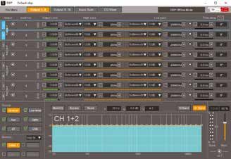
As shown in the next chart the main functions of the software interface include channel
filter selection, sound source selection, EQ, delay, phase, input configuration (mixing), EQ
preview, automatic switchging of sound source, 8-bit password protection can be set to
prevent the tuning file from being tampered etc.
SOFTWARE INTERFACE INTRODUCTIONS
Click the file The delay
menu and setting of each
choose channel is as
Input source long as 8.5
priority: the meters. The
priority of delay value
the selected can be directly
sound input. The
source can group delay
be adjusted. can be
adjusted
synchronously
and the phase
can be
Customize adjusted.
whether the
audio source
The volume
is enabled or
setting has
not.
master
volume and
customized
group volume
Customize and can be
whether the adjusted
presets EQ includes each channel EQ and Main EQ; 10band EQ, 31band EQ, Q value; separately by
enabled or Any frequency point can be adjusted by dragging at will. Main EQ: after channel remote
not. EQ adjustment is done, the overall effect can be tuned through the main EQ. controller.
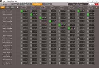
6SOFTWARE INTERFACE INTRODUCTIONS
Input mix switch settings, Input level settings,
synchronous source switching during mixing.
The system will automatically identifies the
model of the DSP products on which is
connected and automatic shields redundant
channel display.
EQ curve display: including level, channel EQ
curve, main EQ curve, and simulated actual
output summation curve.
7TROUBLESHOOTING
Check all the cables and ports all perfectly safe before you switch on the power.
Common troubleshooting procedure:
FILES SUPPORTED
8SPECIFICATIONS
The contents of this manual and the specifications of this product are subjet to change
without notice. DS18 Company reserves the right to make changes to the specifica-
tions and materials contained therein without notice.
9FOR MORE INFORMATION
PLEASE VISIT
DS18.COM
8You can also read