ANSI/PLATO FL 1 Standard - Streamlight
←
→
Page content transcription
If your browser does not render page correctly, please read the page content below
ANSI/PLATO FL 1 Standard
ANSI/PLATO FL1 Standard
•   Why was it created?
•   Who approved the standard?
•   How will manufacturers use it?
•   What does it mean to you?
Why was it created?
• Prior to its creation, there was not any
  standardized testing or any uniform way of
  rating flashlight features.
• This led to confusion for consumers and
  frustration for those companies committed to
  manufacturing quality lights, and publishing
  accurate performance claims.

• The standard was created to help end users
  compare flashlight performance.
• It helps end users rate and compare the
  claims that each manufacturer presents on
  packages.
• A more informed distributor and end-user will
  choose the best flashlight for their needs.

Who decided the standard?
• The standard was developed with the
  guidance of:
  – The American National Standards Institute
  – The National Electrical Manufacturers Assoc.
  – Portable Lights Trade Organization (PLATO)
  – Representatives from 14 companies in the
    portable lighting industry
How do manufacturer’s use it?
• Each manufacturer can decide what claims they choose to
  make on packages and the ANSI/PLATO FL1 standard test(s)
  they complete for each of their portable lighting tools.
• Every flashlight company that participates in this rating
  system can conduct their own tests, adhering to very specific
  guidelines, or use an outside test agency.
• If the standard icon is shown on the packaging, it means the
  flashlight performance claim must comply with the
  ANSI/PLATO FL1 standard.
• If one flashlight claim is based on ANSI/PLATO FL1 standard,
  then all claims presented on the package must adhere to it
  as well.
What does it mean to you?
• It evens the playing field for those manufacturers
  that participate.
• A more informed distributor and end-user will
  choose the best flashlight for their needs.
• Please note that adherence to these standards and
  reporting results is strictly voluntary.
• Many leading flashlight manufacturers have adopted
  the standard.
• The standard helps end users compare the
  flashlight performance claims made and to
  rate and compare the most important features
  of the lighting tools.
• By reviewing the icons and ratings on the
  packages, you can compare the claims for
  brightness, beam distance, impact resistance,
  run time, and water resistance.
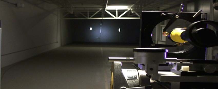
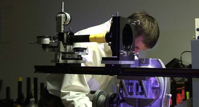
• Peak Beam Intensity and Beam Distance are both
  measured by the same test.
• The light being tested is aimed at a target that is
  placed 2, 10 or 30 meters away. The light output is
  measured by a candela meter that is connected to a
  light sensor on the target
Peak Beam Intensity
• The maximum luminous intensity
  typically along the central axis of a
  cone of light.
• This measures the brightest part of
  the beam. The value is reported in
  candela and does not change with
  distance.
  To determine Peak Beam Intensity:
  Surface light intensity x (distance)2 = peak beam intensity
  (Surface light intensity times distance squared equals Peak Beam Intensity.)
Beam Distance
                       • The distance from the device at which
                         the light beam is 0.25 lux. Results are
                         reported in meters.
                       • The Inverse Square Law is used to
                         calculate the beam distance to .25 lux.
                       • 0.25 lux is approximately the equivalent
                         of the light emitted from the full moon
                         “on a clear night in an open field.”

To determine the beam distance, Inverse square law formula is used:
√(peak beam intensity /0.25 lux)= Max Beam Distance (m)
Purpose: To provide a procedure to determine the peak beam intensity, reported in units of candela, of the device’s beam within 30 seconds to 2 minutes of operation. Power Source: All tests are conducted with fresh batteries or fully charged batteries/energy storage devices. 12V DC devices that are only tethered shall be powered with 13.8V DC using a power supply. Batteries used for testing and claim substantiation shall be of the same type and/or brand as those offered for sale with the product. If the product is sold without batteries and a peak beam intensity claim is made, a specific battery type and chemistry shall be recommended with the package. The batteries recommended by the manufacturer are to be used for testing.
Conditions:
Tests will be conducted at lab conditions, in a dark environment where the
ambient conditions are determined to be less than 1 lux in the entire test area
prior to the test.

If the device offers multiple output levels, the peak beam intensity will be
measured at the maximum level or as otherwise identified.

If the device has variable focusing or adjustable beam angle, the peak beam
intensity will be measured.
Impact Resistance
• The degree to which a
  portable light resists
  damage when dropped on a
  solid surface.
• Dropped samples must not
  exhibit any cracks or breaks,
  and must remain fully
  functional in order to pass
  the Impact Resistance test.
Impact Resistance
Products are dropped onto a concrete surface with all
their intended parts and additions, including batteries,
hand straps, etc. Minimum drop height is one meter.
Impact Resistance
• Higher drop heights can be used for testing and product claims;
  however, any product claiming a drop height different than 1 m
  must meet all passing requirements listed below:
   • Each sample is dropped 6 times using impact orientations that approximate a
     cube.
   • Each sample must be released on each orientation of the approximated cube.
   • Samples must be marked prior to the drop test in a manner that can assure that
     all 6 drop orientations are tested.
   • Samples shall be in the “off” position with batteries in place.
   • The test sample is held in the desired orientation with its lowest part at the
     correct height. Drop the sample onto the impact surface.
   • No additional impetus shall be given to the sample other than the acceleration
     due to gravity.
   • The sample shall be allowed to come to rest after each drop.
Impact Resistance:
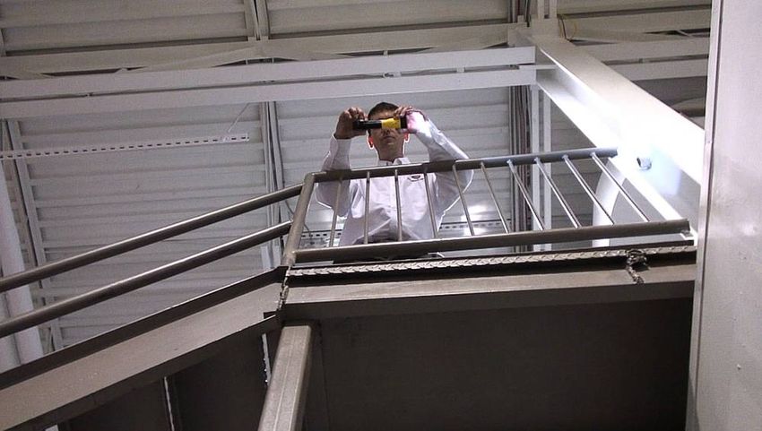
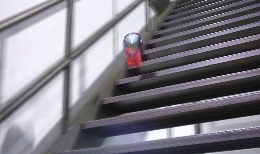
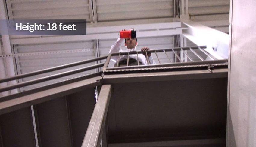
Beyond the ANSI/PLATO FL1 standard
At Streamlight, we conduct additional tests based
on customer requests. Some lights, like the lanterns
carried by firefighters, are dropped down metal
stairs to test their durability and impact resistance.Run Time • The duration of time from the initial light output value (that’s 30 seconds after the light is turned on with fresh batteries) until the light output drops to 10% of the initial value. • Purpose: To determine the amount of time elapsed (under continuous operation) at which the device’s light output reaches a level when users will commonly replace the batteries.
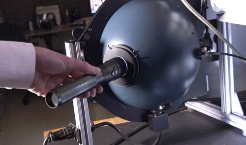
Light Output
• A measurement of the total
  quantity of emitted overall light
  energy as measured by
  integrating the entire angular
  output of the portable light
  source.
• The value is reported in lumens.
• Light Output is the total
  luminous flux.
Run Time and Light Output

Run Time and Light Output are both measured by using a
spectroradiometer with an integrating sphere system and
computing software.

To find the Run Time, the Light Output test is repeated
every 15 minutes until the output drops to 10% of its
initial value.
Water Resistance
• There are three tests that
  measure water resistance:
  – Resistance to Temporary
    Immersion in Water
  – Resistance to Continuous
    Immersion in Water
  – Resistance to Splashing
    Water
Water Resistance
• All test samples shall function
normally immediately after the test
and 30 min after the test. Water
ingress is allowed as long as the
above conditions are met.
• Based on the ANSI/IEC 60529
standard, the following
enclosure ratings for the devices
covered by this standard have been
defined:
• Water Resistant—IPX4—Water
splashed against the device from any
direction shall have no harmful
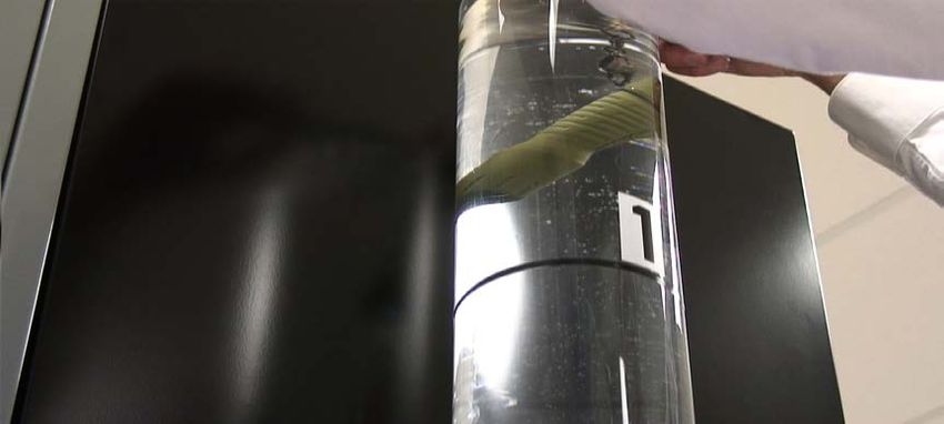
effects.Water Proof • Water Proof – IPX7: Ingress of water in quantities causing harmful effects shall not be possible when the enclosure is temporarily immersed in water under standardized conditions of pressure and time. • Submersible – IPX8: Ingress of water in quantities causing harmful effects shall not be possible when the enclosure is continuously immersed in water under conditions which shall be stated by the manufacturer, but which are more severe than for IPX7.
Water Proof
A 1 m deep reservoir sufficient to cover the entire device with water
or a water vessel that is pressurized equivalent to 1 m depth.

Submersible
A reservoir at the claimed depth sufficient to cover the entire device
with water or a water vessel that is pressurized equivalent to the claim
depth as described in ANSI/IEC 60529, Section 14.2.8 for IPX8 evaluation.
Water Proof and Submersible
All test samples shall function normally immediately after the
test and 30 min after the test.

If the sample passes the water proof and submersible test if
there is no ingress of water in any functional area that contains
unprotected electrical components (contacts, batteries, PCB,
wires) or light sources. Protection shall provide exclusion of
water from the components above.
You can also read