NuSTORM as a Muon Collider Demonstrator - ISIS C. T. Rogers Rutherford Appleton Laboratory - CERN Indico
←
→
Page content transcription
If your browser does not render page correctly, please read the page content below
nuSTORM as a Muon Collider
Demonstrator

                 C. T. Rogers
                      ISIS
        Rutherford Appleton Laboratory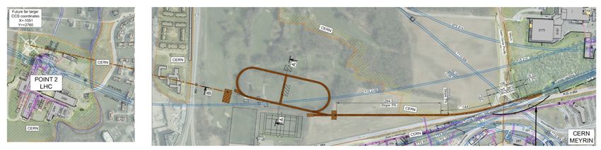
NuSTORM accelerator challenges
nuSTORM facility is a unique facility for
High muon rate
Well-characterised neutrino beam
Several applications
Measurement neutrino scattering cross sections
Search for sterile neutrinos and other BSM physics
Provide a technology test-bed for the muon collider
What is the nuSTORM facility?
What is the physics reach?
How can it provide a test-bed for the muon collider?
2
nuSTORM facility
What is the nuSTORM facility?
nuSTORM at CERN – Feasibility Study, Ahdida et al, CERN-PBC-REPORT-2019-003, 2020
Main features
~250 kW target station
Pion transport line
Stochastic muon capture into storage ring
Option for conventional FODO ring or high aperture FFA ring
3
Target and Pion Transport Line
To decay
ring
Conventional 250 kW target horn
Pion transport line
Proton beam dump
Momentum selection
Active handling
4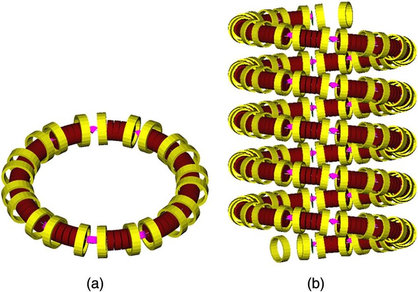
Stochastic Muon Capture
Storage ring OCS
μ acceptance π acceptance
Pions at horn Muons in
decay straight
A. Liu et al, Design and Simulation of the nuSTORM Pion Beamline, NIM A, 2015
D. Adey et al, Overview of the Neutrinos from Stored Muons Facility – nuSTORM, JINST, 2017
Pions injected into the decay ring
Capture muons that decay backwards in pion CoM frame
Undecayed pions and forwards muons diverted into muon test area
Extraction line at end of first decay straight
5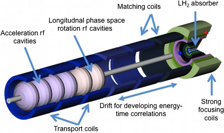
Storage Ring
nuSTORM at CERN – Feasibility Study, Ahdida et al, CERN-PBC-REPORT-2019-003, 2020
Storage ring technologies:
Conventional FoDo ring
High acceptance FFA ring
6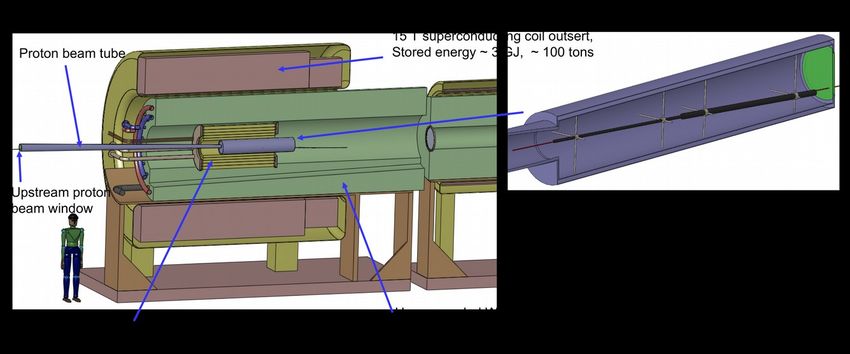
Muon Collider Technical Challenges
Target Station
High-field solenoid in high radiation environment
Target lifetime and radiation damage
Cooling
Rapid cooling in muon lifetime
Acceleration and Collider
Rapid acceleration in muon lifetime
Neutrino radiation management
7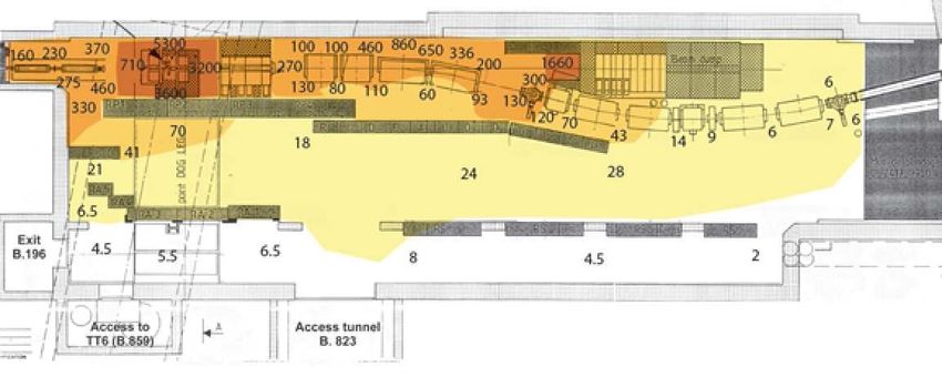
Target
Energy deposition in the target System of a Muon Collider/Neutrino Factory,
Power deposition on target is
an issue
Radiation damage to target
K. McDonald et al, IPAC14
material
Heat load on target and
cryogenic cooling requirement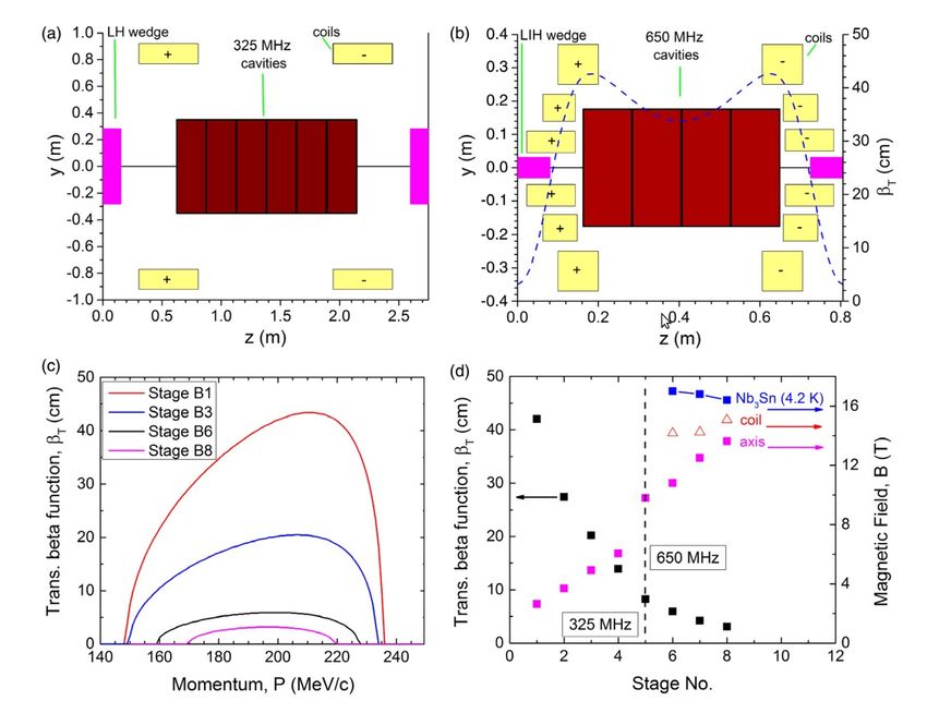
Ionisation Cooling
Absorber
RF MUONS
Beam loses energy in absorbing material
Absorber removes momentum in all directions
RF cavity replaces momentum only in longitudinal direction
End up with beam that is more straight
Multiple Coulomb scattering from nucleus ruins the effect
Mitigate with tight focussing
Mitigate with low-Z materials
Equilibrium emittance where MCS completely cancels the
cooling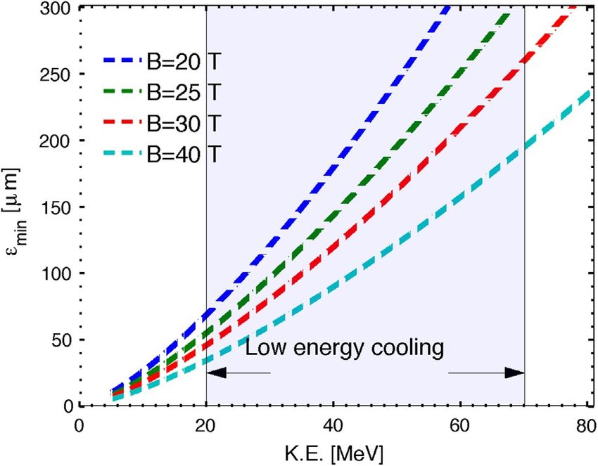
Muon Cooling
“MICE-like”
Final
cooling
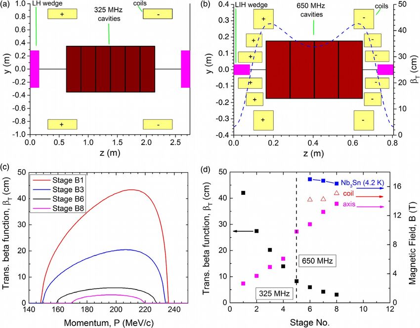
Rectilinear B (Stage B8)
MICE
10Cooling Risks
Performance does not match simulation, for example because Further experimental measurements of energy
energy straggling is underestimated, alignments can’t be achieved, Literature review on straggling; simulation study straggling may be necessary. Integration test of
Rectilinear B etc 3 Reduced performance 2 of impact on uncertainty in straggling distribution cooling apparatus.
Proof of breakdown suppression with a
“production” cavity and a reasonable production
RF voltage cannot be achieved, for example because gradients are run of several cavities, including realistic
found to be above break down limit 3 Back off on RF requirements 2 magnetic fields
Design of magnets is required including e.g. Prototyping of magnets. Demonstration of QPS
Magnetic field strength cannot be achieved 3 Back off on magnet requirements 3 force calculations, support design system in a reasonable magnet line.
Radiation load on the magnets is too high due to regular beam Back off on magnet requirements
losses and muon decay 2 and add extra shielding 1
Heat load on the absorber is challenging to manage 1 Split the beam? 3 Further simulation and design work
Beam loading of RF cavities
Space charge
Further optimisation of the cooling channel Further experimental measurements of energy
design. Alternative concepts such as frictional straggling may be necessary. Integration test of
Final Cooling Performance does not match requirements 4 Reduced performance 3 cooling should be considered cooling apparatus.
Proof of breakdown suppression with a
“production” cavity and a reasonable production
RF voltage cannot be achieved, for example because gradients are run of several cavities, including realistic
found to be above break down limit 3 Back off on RF requirements 2 magnetic fields
Design of magnets is required including e.g. Prototyping of magnets. Demonstration of QPS
Magnetic field strength cannot be achieved 3 Back off on magnet requirements 3 force calculations, support design system in a reasonable magnet line.
Radiation load on the magnets is too high due to regular beam Back off on magnet requirements Calculations; radiation shielding for high field
losses and muon decay 3 and add extra shielding 3 magnets
Heat load on the absorber is challenging to manage 1 Split the beam? 3 Further simulation and design work
Beam loading of RF cavities
Space charge
Principle risks are at the low emittance end of the cooling
channel
Extremely high magnetic field
More intense beam 11Rectilinear B8 (Stratakis et al)
Stop Stop
Band Band
Rectilinear B8
Challenges
Maintaining adequate acceptance between stop bands
Dispersion and closed orbit control
Successful RF operation and suppression of RF breakdown
Magnet engineering
Integration of magnet with RF and absorber
Day-to-day operation
Also intensity/collective effects
Space charge, beam loading, absorber/RF window heating
Decay radiation load on magnets 12Rectilinear B8
ABC
13Rectilinear B8
5 metres after
ABC lattice start
14Rectilinear B8
ABC
15Rectilinear B8
ABC
16Rectilinear B8
|V(x, px, y, py)|1/2
mμ
|V(ct, E)|1/2
ABC mμ
17Rectilinear B8
Upstream Downstream
Focus 1.5 T Focus 1.5 T
Transverse
Emittance [mm] 0.4 0.32
Transverse Beta
[mm] 29 890 29 890
sigma(x) [mm] 2.5 13.7 2.3 12.3
Sigma(px) [MeV/c] 17.8 3.1 15.5 2.8
Mean momentum
[MeV/c] 200 200
Longitudinal
Emittance [mm] 2.2 1.8
sigma(t) [ns] 0.095 0.084
sigma(E) [MeV] 9.5 8.6
Beam parameters upstream and downstream of 40 m cooling
channel (50 cells)
“Focus” is at the focus of the rectilinear channel
1.5 T is in a uniform 1.5 T solenoid
Might imagine matching beam in/out of rectilinear for
diagnostics/etc
18Final cooling (Sayed et al)
19Final cooling
20Final Cooling - Summary
Upstream Downstream
Focus 1.5 T Focus 1.5 T
Transverse
Emittance [mm] 0.072 0.055
Transverse Beta
[mm] 18 320 18 320
sigma(x) [mm] 1.4 5.8 1.2 5.1
sigma(px) [MeV/c] 5.5 1.3 4.8 1.1
Mean momentum
[MeV/c] 71 71
Longitudinal
Emittance [mm] 53 62
sigma(t) [ns] 4.9 5.7
sigma(E) [MeV] 3.8 3.8
Beam parameters upstream and downstream of single cooling
cell
“Focus” is at the (high field) focus of the solenoid
1.5 T is in a uniform 1.5 T solenoid
21Solenoid Cooling Ring (Muons)
R, Palmer et al, Phys. Rev. ST Accel. Beams 8, 061003 (2005)
Absorber
RF Solenoid+ Number of Cells 12 Abs thickness 28 cm
Cavity Dipole
Radius 5m Abs material liquid H2
Energy 250 MeV Voltage/turn ~120 MV
Solenoid field 2.8 T RF phase 25 degrees
Dipole field 0.15 T RF freq 201 MHz
22Solenoid Cooling Ring (Muons)
Upstream Downstream
Focus Focus
Transverse
Emittance [mm] 12 3.3
Transverse Beta
[mm] 400 400
sigma(x) [mm] 50 26
Sigma(px) [MeV/c] 25 13
Mean momentum
[MeV/c] 200 200
Longitudinal
Emittance [mm] 18.4 4.8
sigma(t) [ns] 0.805 0.411
sigma(E) [MeV] 8.05 4.1
More MICE-like
Consider pion stochastic injection like nuSTORM?
No need to extract
But not like a “realistic” muon collider cooling ring
Would need to design low emittance cooling option
23Input beam
Bring beam energy down by low-Z energy absorber
Generate transverse distribution by collimation
Longitudinal distribution not so straight forward
(Solenoid) chicane to generate dispersion + collimators?
RF kickers to generate time structure?
Need to leave enough muons that they can be measured!
24Storage Ring Phase Space
Racetrack FFAG muon decay ring for nuSTORM with triplet focusing, Lagrange et al, J.Inst (2018)
38 30.4
Px [MeV/c]
Pz [MeV/c]
0 0
-38 -30
Muon phase space in the nuSTORM storage ring
Central momentum 3.8 GeV/c
25Survey of Muon Beamlines
Possible muon beam test areas
Possible muon targetry test area
MC Front End Baseline Muon Collider Rings NuSTORM would make an
excellent facility
nuSTORM
target and ring One of the highest current high
energy muon beams
Deal with routine issues
E.g. routine operation of
equipment in presence of muon
nuSTORM decays
pion dump
Target/irradiation test area
Muon beam physics tests
26Discussion
Few options for ionisation cooling tests considered
Worth thinking about how we can make the beams
Probably intensity limit is ruled out – for muons at least
Do we build a proton test facility elsewhere?
27You can also read