Oxygen Generation and Storage - PATH | CLINTON HEALTH ACCESS INITIATIVE
←
→
Page content transcription
If your browser does not render page correctly, please read the page content below

FOR: DECISION-MAKERS

                                                       SUPPLY INTELLIGENCE

Oxygen
Generation and
Storage

July 2021

            PATH | CLINTON HEALTH ACCESS INITIATIVE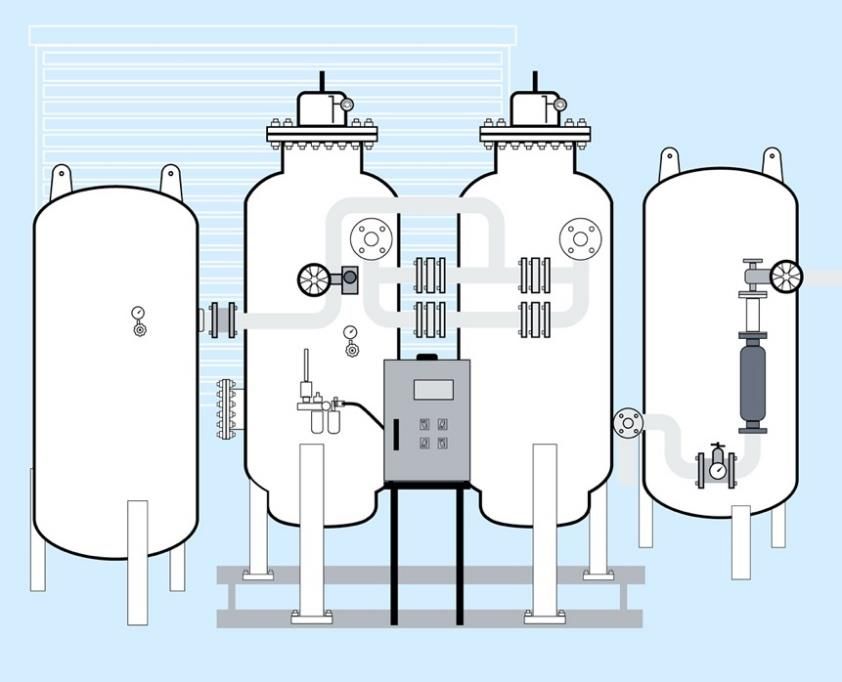
Acknowledgments
This brief series is based on research funded by the Bill & Melinda Gates Foundation. The findings and conclusions contained
within are those of the authors and do not necessarily reflect positions or policies of the Bill & Melinda Gates Foundation.

The brief series was developed by PATH and Clinton Health Access Initiative (CHAI) as part of the COVID-19 Respiratory Care
Response Coordination project—a partnership between PATH, CHAI, and the Every Breath Counts coalition to support country
decision-makers in the development and execution of a comprehensive respiratory care plan to meet the demands of COVID-
19. The project is also pursuing strategies to help prioritize and improve access to oxygen therapy and other essential
equipment involved in respiratory care as an integral part of health systems strengthening, beyond the pandemic response.
For information: oxygen@path.org.

The brief series was written by PATH staff Scott Knackstedt, Alex Rothkopf, Stassney Obregon, and Alec Wollen, with support
from CHAI staff Jason Houdek, Martha Gartley, and Tayo Olaleye. The authors would like to thank the following individuals for
their insightful feedback, including Lisa Smith, Andy Gouws, Evan Spark-DePass, Elena Pantjushenko, Carrie Hemminger, and
Conner House.

                                                                                                                                i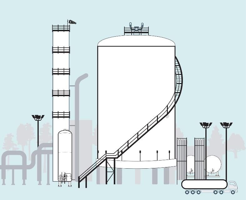
Table of contents
Introduction .................................................................................................................................................................................. 2
Air separation unit ........................................................................................................................................................................ 3
   Technical overview ................................................................................................................................................................................ 3
   Key specifications .................................................................................................................................................................................. 3
   Regulatory considerations ..................................................................................................................................................................... 3
   Infrastructure requirements .................................................................................................................................................................. 4
   Supply/shipping ..................................................................................................................................................................................... 4
   Dependencies for use ............................................................................................................................................................................ 4
   Maintenance.......................................................................................................................................................................................... 5
   Cost ........................................................................................................................................................................................................ 5
   COVID-19 considerations ....................................................................................................................................................................... 5
Pressure/vacuum swing adsorption plant ...................................................................................................................................... 6
  Technical overview ................................................................................................................................................................................ 6
  Key specifications .................................................................................................................................................................................. 6
  Regulatory considerations ..................................................................................................................................................................... 7
  Infrastructure requirements .................................................................................................................................................................. 7
  Supply/shipping ..................................................................................................................................................................................... 7
  Dependencies for use ............................................................................................................................................................................ 7
  Maintenance.......................................................................................................................................................................................... 8
  Cost ........................................................................................................................................................................................................ 8
  COVID-19 considerations ....................................................................................................................................................................... 8
Vacuum-insulated evaporator system............................................................................................................................................ 9
  Technical overview ................................................................................................................................................................................ 9
  Key specifications .................................................................................................................................................................................. 9
  Regulatory considerations ................................................................................................................................................................... 10
  Infrastructure requirements ................................................................................................................................................................ 10
  Supply/shipping ................................................................................................................................................................................... 10
  Dependencies for use .......................................................................................................................................................................... 11
  Maintenance........................................................................................................................................................................................ 11
  Cost ...................................................................................................................................................................................................... 11
  COVID-19 considerations ..................................................................................................................................................................... 11
Oxygen concentrators ................................................................................................................................................................. 12
  Technical overview .............................................................................................................................................................................. 12
  Key specifications ................................................................................................................................................................................ 12
  Regulatory considerations ................................................................................................................................................................... 12
  Infrastructure requirements ................................................................................................................................................................ 12
  Supply/shipping ................................................................................................................................................................................... 13
  Dependencies for use .......................................................................................................................................................................... 13
  Maintenance........................................................................................................................................................................................ 13
  Cost ...................................................................................................................................................................................................... 13
  COVID-19 considerations ..................................................................................................................................................................... 14
Oxygen cylinders ......................................................................................................................................................................... 15
  Technical overview .............................................................................................................................................................................. 15
  Key specifications ................................................................................................................................................................................ 15
  Regulatory considerations ................................................................................................................................................................... 16
  Infrastructure requirements ................................................................................................................................................................ 16

                                                                                                                                                                                                                ii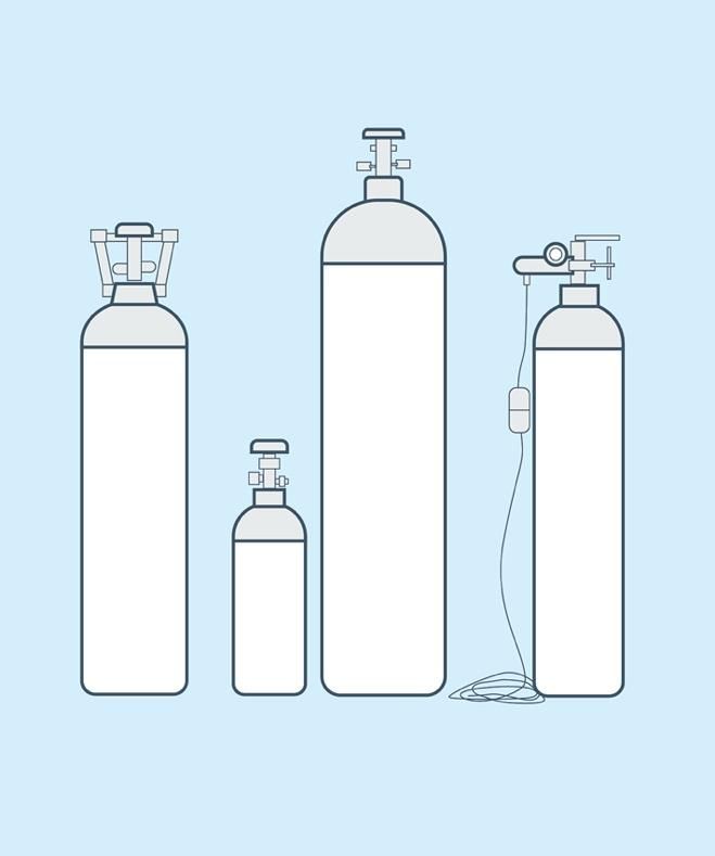
Supply/shipping ................................................................................................................................................................................... 16
    Dependencies for use .......................................................................................................................................................................... 17
    Maintenance........................................................................................................................................................................................ 17
    Cost ...................................................................................................................................................................................................... 17
    COVID-19 considerations ..................................................................................................................................................................... 17
Oxygen therapy accessories......................................................................................................................................................... 18
  Technical overview .............................................................................................................................................................................. 18
  Key specifications ................................................................................................................................................................................ 18
  Regulatory considerations ................................................................................................................................................................... 18
  Infrastructure requirements ................................................................................................................................................................ 19
  Supply/shipping ................................................................................................................................................................................... 19
  Maintenance........................................................................................................................................................................................ 19
  Cost ...................................................................................................................................................................................................... 19
  Additional information ........................................................................................................................................................................ 20
  COVID-19 considerations ..................................................................................................................................................................... 20
Oxygen therapy interfaces ........................................................................................................................................................... 21
  Technical overview .............................................................................................................................................................................. 21
  Key specifications ................................................................................................................................................................................ 21
  Regulatory considerations ................................................................................................................................................................... 22
  Infrastructure requirements ................................................................................................................................................................ 22
  Supply/shipping ................................................................................................................................................................................... 22
  Maintenance........................................................................................................................................................................................ 22
  Cost ...................................................................................................................................................................................................... 22
  COVID-19 considerations ..................................................................................................................................................................... 23

                                                                                                                                                                                                               iii
Abbreviations
ASME          American Society of Mechanical Engineers
ASU           air separation unit
CE            European certification
DISS          Diameter Index Safety System
FDA           Food and Drug Administration
Hz            hertz
ISO           International Organization for Standardization
kPa           kilopascals
kWh           kilowatt hours
LOX           liquid oxygen
LPM           liters per minute
NFPA          National Fire Protection Association
Nm3           normal cubic meters
PSA           pressure swing adsorption
psi           pounds per square inch
V             volt
VIE           vacuum-insulated evaporator
VSA           vacuum swing adsorption
WHO           World Health Organization

Unit conversion
 Kilopascal (kPa)           Unit of pressure, defined as one thousand times the unit of force of 1 Newton     1 kPa = 0.145 psi = 0.0099
                            uniformly distributed over an area of 1 square meter                              atmosphere = 0.01 bar
 Atmosphere                 Unit of pressure, defined as the pressure exerted by 760 millimeters of mercury   1 atmosphere = 101.3 kPa =
                            at 0 °C and standard gravity                                                      14.7 psi = 1.013 bar
 Pounds per square inch     Unit of pressure, defined as the force exerted on an object expressed in pounds   1 psi = 6.89 kPa = 0.070
 (psi)                      of force per square inch of area                                                  atmosphere = 0.069 bar
 Pounds per square inch     Unit of pressure, relative to the ambient or atmospheric pressure                 psig = absolute pressure –
 gauge (psig)                                                                                                 atmospheric pressure
 Liters per minute (LPM)    Unit of volume flow rate                                                          1 LPM = 0.06 Nm3/h
 Normal cubic meters per    Unit of volume flow rate, where ‘normal’ refers to being measured at standard     1 Nm3/h = 16.7 LPM
 hour (Nm3/h)               temperature and pressure (101.325 kPa, 0oC)

                                                                                                                                           1
Introduction
Medical oxygen has for too long been an afterthought among the competing priorities of global health. It is a World Health
Organization (WHO) essential medicine and necessary treatment for acute and chronic conditions alike, but inequitable
access, production shortages, logistical failures, and a host of additional circumstances have inhibited the widespread
adoption and consistent provision of this lifesaving resource. The SARS-CoV-2/COVID-19 pandemic has given added salience to
the importance of medical oxygen and made stark the seriousness that a lack of access creates. As governments and health
systems come to terms with the harsh realities that the pandemic has laid bare, and the resulting political capital and social
engagement is mustered, there is a robust opportunity to make inroads against this inequity and help ensure that patients the
world over can again breathe easy—in more ways than one.

This supply intelligence brief series, Oxygen Generation and Storage, is intended to be a concise primer for decision-makers
who govern, lead, support, or manage health systems and their associated facilities. Providing an overview of the key
elements that define each technology—as well as key considerations related to COVID-19—it can establish a starting point for
understanding the solutions available to meet a health system’s need for medical oxygen and its delivery. It should serve
alongside a broader suite of planning and analytical requirements necessary for the implementation of medical oxygen
solutions. As interest from governments, international organizations, and other stakeholders have coalesced behind this issue,
the opportunity is ripe for those decision-makers to act and to do so with the judgment, responsibility, and respect befitting
the patients that have for too long suffered without this necessary commodity.

                                               SUPPLEMENTAL RESOURCES

 World Health Organization (WHO). Technical Specifications for Oxygen Concentrators. Geneva: WHO; 2015.
 http://apps.who.int/iris/bitstream/handle/10665/199326/9789241509886_eng.pdf?sequence=1.

 World Health Organization (WHO), United Nations Children's Fund (UNICEF). WHO-UNICEF Technical Specifications and
 Guidance for Oxygen Therapy Devices. Geneva: WHO; 2019. https://apps.who.int/iris/handle/10665/329874.

 World Health Organization (WHO). Chapter 3: Technical specifications for oxygen therapy and monitoring devices. In:
 Priority Medical Devices List for the COVID-19 Response and Associated Technical Specifications. Geneva: WHO; 2020.
 https://www.who.int/medical_devices/priority/Chapter_3_20167_WHO_Priority_medical_devices_list_for_COVID_19_
 response_3.pdf?ua=1.

 PATH, Clinton Health Access Initiative. Respiratory Care Equipment Market Report. Seattle: PATH; 2020.
 https://www.path.org/resources/respiratory-care-equipment-market-report/.

                                                                                                                             2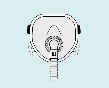
Air separation unit
Technical overview
A cryogenic air separation unit (ASU) is a plant that utilizes
the distinct properties between the primary components of
air to produce highly purified oxygen, nitrogen, and
sometimes other gases, such as argon. The ASU technology
uses a process referred to as cryogenic fractional
distillation, where the components of the air are separated
by compressing the gas until it liquefies at extremely low
temperatures (-173°C to -193°C), then selectively distilling
the components at their various boiling temperatures. As it
is a very energy-intensive process, ASU technology is
generally reserved for medium- to large-scale production.
An ASU can be designed for the required product purity and
delivery pressures. Skilled technicians are required on-site
at all hours to ensure smooth operation of the plant.

Key specifications
An ASU can produce 100 to over 5,000 tons of oxygen per day at purity levels of 95% to 99.5% or higher. The process of air
separation consists of the following main steps:

  •   Filtration, to remove dust and other impurities.
  •   Compression, where the air is compressed between 72 to 144 psig and water is condensed out in inter-stage coolers.
  •   Removal of contaminants, using a molecular sieve bed, which is constantly regenerated to remove any remaining water
      vapor, hydrocarbons, and carbon dioxide, which would freeze and plug the cryogenic equipment.
  •   Heat exchange, where the air is passed through integrated heat exchangers and cooled against product and waste
      cryogenic streams to produce liquefied air enriched in oxygen and nitrogen. This happens in separate low- and high-
      pressure distillation columns using refrigeration.
  •   Product compression, where oxygen is compressed to a prescribed settled pressure.
  •   Storage, where the liquid oxygen produced from the ASU is stored in cryogenic insulated storage tanks.

The construction of an ASU plant varies depending on the production capacity, purity, and pressure requirements for the
application and may influence the materials used in its construction. For oxygen, carbon steel is commonly preferred due to
cost and its effectiveness at the extreme temperatures endured during ASU operation.

Regulatory considerations
If the product is intended for medical application, an ASU must be certified for medical oxygen production and all liquid
oxygen (LOX) storage tanks must be certified both at the site of the ASU and at the medical facility. Analytical equipment using
high-purity oxygen analyzers are used in the ASU production process to ensure that the oxygen produced by the ASU is of
                                                                                                                               3
medical-grade quality and complies with European and US pharmacopeia directives. A quality system or testing validation
process of the product is carried out on a regular basis to ensure the oxygen produced complies with the international medical
gas standards. Refrigerants used to facilitate the low temperatures necessary for an ASU plant, such as
hydrochlorofluorocarbons and some halocarbons, may need to be regulated by local authorities. An evaluation of local
environmental regulations and guidelines may be required, and pressure vessels may need to be built to comply with local
codes.

Infrastructure requirements
Two key infrastructure requirements for ASU technology include electricity and cooling water:

  •   Electricity: An ASU relies on large amounts of energy (either from electricity or other fuel sources) to maintain the
      cryogenic temperatures necessary for the process. For example, a 1,200-metric ton per day ASU uses over 16
      megawatts of power when operating and will require a local utility company to install a dedicated power supply.
  •   Cooling water: An evaporative cooling water system (either open or closed) is required to cool the compressors and
      process air during the production process.

Supply/shipping
For the plant: Depending on the size and location of the facility, the duration—from the onset of the project to the first
delivery of oxygen—can exceed 18 to 24 months. In addition to the mechanical equipment supplied by a manufacturer of ASU
facilities, plant construction may depend on the services of multiple contractors, including excavation, concrete installation,
piping installation, electrical and instrument installation, column assembly and aluminum welding, and oxygen cleaning and
lube oil flushing, among others, and any one service may depend on the successful completion of another. Additionally,
construction can be delayed during wet seasons in certain geographies, sometimes in excess of 45 days per year. Thorough
project planning in close collaboration with the manufacturing partner will help optimize construction timelines.

For the oxygen generated: Given the scale of production, energy requirements, and associated risks, liquid oxygen is always
produced off-site. In order to use liquid oxygen for medical application, there are additional equipment needs for transport,
storage, and use. Different network supply and distribution options are used by different companies. The structure of a
company’s network can determine how quickly a supplier can respond to orders and how costly shipping is. Any liquid oxygen
provider’s anticipated lead-times will have to be factored in when planning for refill frequency to ensure continuity of supply.

If demands are larger, consideration should be given to installing a vacuum-insulated evaporator (VIE) tank at the health
facility, sized according to refill frequency, and an evaporator, sized to meet demand. If demands are smaller, or for back-up
considerations, high-pressure gas cylinders are used. There is also the option of liquid cylinders, which have built-in vaporizers
and connect to a distribution manifold. However, given the potential usable volume, they are rarely the most efficient option.
All storage vessels must be certified for use with medical oxygen. For delivery, cryogenic tanker trucks are used for liquid
oxygen and must be certified for medical use. Trucks transporting oxygen cylinders should comply with safety protocols for
transporting compressed gases.

Dependencies for use
Related equipment needed with an ASU are static vacuum-insulated storage vessels for the storage of LOX, a vaporizer at the
site of production, a high-pressure gaseous cylinder filling plant to fill cylinders, and trucks to transport LOX and cylinders. For
delivery purposes, cryogenic trucks and storage vessels must be validated for use with medical oxygen and cryogenic vacuum-
insulated storage vessels must be present at or adjacent to the medical facility.

                                                                                                                                   4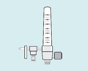
Maintenance
Major maintenance requires the plant be taken offline for hours to days, and supply chains must plan accordingly to
accommodate the gap in production. Key requirements for appropriate maintenance of ASU technology include:

  •   Labor: Well-trained operators (typically 3 operators operating 3 shifts of 8 hours each) and technical maintenance
      support staff (operation managers, millwrights, and instrument technicians) are required to operate and maintain the
      production facilities 24/7.
  •   Liquid oxygen transport: LOX is a hazardous good and countries typically have specific regulations in place to guide its
      safe transportation. LOX intended for large medical facilities is usually transported by specialized road tankers to be
      decanted into a cryogenic vacuum-insulated storage tank located at the medical facility. For large industrial gas users,
      gaseous oxygen may be supplied via pipeline directly to the point of use.
  •   Cylinder filling: Depending on the facility, LOX can be vaporized into a gas and filled into cylinders using high-pressure
      compressors, or via a cryogenic pump and vaporizer, and transported in cylinder trucks or a flatbed truck modified for
      the safe transport of high-pressure gas cylinders.

Cost
The capital cost for an ASU plant is significant, and there are critical factors to consider. The first is plant size; determining the
requisite size may be informed by demand and its anticipated growth rate. If demand growth is 8%, for example, plant size
should allow for an initial loading of 50% capacity to enable it to reach full capacity in approximately 9.5 years. The second
critical factor to consider is the distance to the user base, as transportation costs will affect the cost of the product and,
ultimately, the return on investment of the ASU plant. Third, the cost of power will determine whether a more efficient plant
should be built at the expense of a higher capital outlay. On average, 75% of a 200-metric ton per day ASU plant’s total
lifetime costs are energy costs. When taken together, capital costs can range from approximately US$25 million for a 200-
metric ton per day plant to US$125 million for a 3,000 ton per day plant.

From a gas supplier’s perspective, a high level of capital investment is common for an ASU due to the equipment
requirements to support the production facilities. To ensure optimized plant operation, the gas supplier will enter into long-
term contracts with medical facilities as well as large industrial gas users who will pay for service on a monthly, quarterly, or
another period of frequency as determined by the contract. Accompanying infrastructure—including cryogenic vacuum-
insulated storage tanks, generators, appliances, cylinder filling plant, trucks, and offices—will also require notable capital
outlay. In order for the plant to achieve cost-effective production, its capacity utilization must be optimized. For the gas
supplier, key operating costs include electricity, labor, and maintenance.

COVID-19 considerations
In the context of a global pandemic like COVID-19, additional considerations should be raised. Liquid oxygen offers the most
affordable cost-per-liter pathway to deliver oxygen to facilities with high demand and is suitable for large referral hospitals
with high patient loads related to COVID-19 or acute respiratory distress syndrome. This cost benefit is realized when facilities
are located close to an existing liquid oxygen production plant or bulk storage hub, depending on the distribution model.
However, although an ASU can affordably provide a large supply of oxygen, the time required to build and begin production
will take longer than other generation modalities available, and construction is resource intensive. (For additional
considerations, see Vacuum-insulated evaporator system section.)

                                                                                                                                     5
Pressure/vacuum swing adsorption plant
Technical overview
Oxygen can be generated by using pressure swing
adsorption (PSA) technology, which concentrates oxygen
from ambient air. In this process, the air is dried, and
impurities, such as carbon dioxide, hydroc/arbons, and
water, are removed. The air passes into pressure
adsorption vessels fitted with interconnecting valves that
house zeolite material—a porous mineral containing
aluminum and silicon compounds—that preferentially
adsorbs nitrogen while allowing oxygen to pass through.
Once the zeolite is saturated and the oxygen collected,
the pressure in each adsorption vessel is reduced
(swinging from high to low), and the nitrogen is released
to allow more air to be treated to produce oxygen using
the same zeolite. An on-site PSA plant can supply high-
pressure oxygen throughout a hospital via a central
pipeline system or cylinders filled at the plant.
Vacuum swing adsorption (VSA) technology also uses a
zeolite sieve for separating the oxygen and nitrogen, but plants utilize a vacuum blower instead of an air compressor and a
smaller number of adsorption vessels and valves. These systems are more energy-efficient, have lower operating costs, and
can operate at higher altitudes without a reduction in performance, but typically have a higher upfront capital cost than a
comparable PSA plant. They also produce oxygen at a much lower pressure than a PSA plant and often require an additional
high-pressure oxygen compressor to boost pressure to meet needs of health facility piping networks. When selecting either a
PSA or VSA system, irrespective of the technology, it is most important that the tender includes robust technical and
performance requirements based on the intended use case and location.
Key specifications
PSA and VSA plants can vary in size and capacity, but basic specifications include oxygen production purity at 93% ±3% and
continuous output pressure of 50 to 55 pounds per square inch gauge (psig) (US NFPA 99: Health Care Facilities Code) or 400
to 500 kilopascals (kPa) (ISO; piping only). They are designed for a minimum life span of 10 years and should be capable of
supplying the specified oxygen concentration continuously in ambient temperatures from 10°C to 40°C, relative humidity from
15% to 95%, and elevation from 0 to at least 2,000 meters. A PSA/VSA plant should include audible and visual alarms in the
event of power failure, system failure, or when oxygen concentration falls below 90% purity. For a conventional PSA plant, the
nominal flow rate ranges from 8 to 2,500 liters per minute (LPM) (0.5 to 150 normal cubic meters per hour [Nm3/h]) at 50 psi.
VSA plants can achieve nominal flow rates of 52 to 3,155 Nm3/h at 5 psig (34.5 kPa).
6Regulatory considerations
PSA and VSA plants should have European certification (CE marking) or other stringent regulatory authority approval. Relevant
guidelines include ISO 7396-1 and/or US/European Union pharmacopeia compliance standards for oxygen at 93% production
purity. Registration with local health authorities may be necessary if distributing cylinders outside the facility.
Infrastructure requirements
PSA/VSA plants all require electricity and sufficient ambient air flow. For electricity, a continuous and reliable source of power,
ideally 230V single-phase (for VSA and valve operations) and 380V–400V three-phase power at 50 Hz (for PSA and
compressor/dryer operations), is necessary. Although there can be notable variation, a conventional PSA plant requires
approximately 1.2 kilowatt hours (kWh) per Nm3 produced at 65 psig, depending on system efficiency and oxygen service
pressure. For a VSA plant, approximately 0.39 kWh per Nm3 of total flow at 2.7 psig is necessary, depending on system
efficiency. Energy consumption will increase for higher service pressures and if cylinder filling is required.
For operational requirements, certain environmental conditions must be met, such as air conditioning, roofing, and a proper
ventilation system to ensure clean air intake for breathing; also, the designated area must not have flammable products
present. The equipment generates substantial amounts of heat and requires adequate air conditioning for cooling. A PSA
plant, if skid-mounted, should be in a well-ventilated housing, for security and protection from adverse weather conditions.
To note, PSA/VSA plants are also commonly configured with medical oxygen piping. Hospital pipeline systems typically supply
oxygen at higher pressure to equipment such as anesthesia machines and ventilators. These systems eliminate the need for
transporting heavy cylinders between hospital wards and should be composed of type L copper tubing and brazed copper
fittings. A backup supply (e.g., cylinders) is required to maintain oxygen flow in case of a power outage or mechanical failure.
In lieu of piping, some hospitals will instead use a compressor and fill cylinders for local use.
Supply/shipping
Depending on size, customization, and supplier’s capacity, production lead times range from 2 to 24 weeks. In addition,
depending on the port of origin and final destination, 2 to 12 weeks of shipping lead time is required. Installation requires
complex logistics to ship multiple containers from the port of entry to the final destination, and the time required to develop
the installation site must be considered (and can be done in parallel). Systems may be assembled on-site or are available pre-
assembled on a skid or shipping container installation. Furthermore, considerations should be made the routine maintenance
and repairs, which will require a supply of spare parts. In many settings, a stockpile of manufacturer-recommended spare
parts is advised to ensure interruptions remain short.
Dependencies for use
Depending on manufacturer recommendations, a compressed air surge tank and/or oxygen receiver tank, an air compressor,
and a filter/drier for the air compressor may be required. In that event, it is common for PSA/VSA manufacturers to provide
recommended models or specifications with additional equipment as a package. For piping, flowmeters and regulators are
necessary. Other related equipment could include a high-pressure oxygen compressor, in the event that the PSA/VSA plant
will be used for cylinder filling.
7Maintenance
For preventive (scheduled) maintenance, a buyer/owner can contract with the manufacturer for maintenance that requires
highly trained technicians and engineers. This can include cleaning or replacing filters, draining water or oil traps, replacing
lubricants, and calibrating pressure and oxygen sensors. The plant operating environment should be maintained with correct
ventilation and cooling. Although common, such a maintenance agreement may not always be feasible, and in such an
instance, buyers should evaluate whether there are trained technicians or qualified third parties available to service the
system.
For corrective maintenance, it may be necessary to rebuild a valve assembly or compressor in the event of failure.
Additionally, sieve beds must be recharged periodically if there is a reduction in performance in the oxygen generating
capacity or purity.
Cost
The investment costs for a PSA or VSA plant depends on size, functionality, equipment, whether accessories (or other
products) are purchased, and whether the product is containerized (which would require lower plant housing costs).
Generally, PSA plants require a lower capital expenditure than VSA plants, which command a 10% to 20% premium in upfront
costs, and may require a compressor to feed a piped system. The improved efficiency of VSA plants, however, could allow for
notably lower operating costs that balance the upfront costs quickly. As a reference, for a large hospital (greater than 1,000
beds) in east Africa requiring a total oxygen capacity of 4,114 kg per day of 93% purity, a PSA plant solution is estimated to
cost US$800,000 with anticipated monthly operating expenditures of US$1,900 to cover electricity, service, and maintenance.
A VSA plant for the same hospital, daily volume, and purity is estimated at approximately US$880,000 with anticipated
monthly operating expenditures of US$1,000. For smaller health facilities (150 to 200 beds), a plant with suitable production
volumes will be closer to US$100,000 to US$110,000. Prices may vary significantly depending on manufacturer, production
volume, purity level, and other factors. In general, a CE mark or other stringent regulatory approval on a plant will add
approximately 5% to the price of a new unit. It is important to research local production demands and thoroughly understand
the operating requirements and associated costs of the equipment under consideration.
COVID-19 considerations
In the context of a global pandemic like COVID-19, additional considerations should be raised, including:
• PSA and VSA plants can be scaled depending on production volume needs. Smaller plants can be skid-mounted and
delivered to health facilities for on-site production. Large, permanent systems can be built farther afield and oxygen
from the facility can be stored in cylinders and delivered via cylinder trucks. Further, PSA and VSA plants can be
configured for dual use when the plant is co-located at a health facility with directly piped oxygen supply along with a
booster compressor to fill and distribute oxygen cylinders to other, nearby health facilities.
• Smaller, on-site plants are largely self-sufficient and do not require constant technician involvement, but qualified staff
presence is necessary to prevent problematic outcomes.
• On-site PSA/VSA systems should ensure infection control practices are relevant to the piping system that delivers the
oxygen from the plant to the patient rooms.
8Vacuum-insulated evaporator system
Technical overview
A cryogenic liquid oxygen storage tank is an insulated vessel
consisting of a carbon steel outer shell and a stainless-steel
inner vessel, with an insulating vacuum space between the
layers to minimize heat ingress. Oxygen liquifies at -183°C at
one atmosphere of pressure and is generally stored at
pressures closer to 23 atmospheres. Together with
vaporizers, valves, piping, and a pressure control and
pressure relief system, the tank constitutes a vacuum-
insulated evaporator (VIE), which can supply a central
oxygen piping system in a medical facility and is often
leased from the medical gas supplier. Oxygen enters the
piping system after passive evaporation in the vaporizer,
and therefore does not require a source of power. VIEs can
be configured to fill cylinders, too, without electricity.
Transporting oxygen to these tanks and storing it as a liquid
takes less space and is less expensive than moving and
storing it as a gas under high pressure, as one liter of liquid oxygen produces 861 liters of gaseous oxygen. Although liquid
oxygen is economical for facilities that use large quantities, the bulk liquid to fill the tanks is produced at a cryogenic air
separation unit (ASU) and requires a specialized bulk road tanker for transport from ASU to VIE. Careful handling is required
due to the possibility of accidentally rupturing the pressurized tank, which could lead to safety risks such as cold burns and a
source of ignition for fires.
Key specifications
Key requirements for properly operating VIEs include:
• A cryogenic liquid oxygen tank which can be installed in a vertical or horizontal position.
• Capacity typically ranges from 500 to 25,000 liters of liquid oxygen storage for health facility use. Larger capacity units
can be custom built as needed.
• The maximum allowable working pressure ranges from 1 to 37 atmospheres.
• Hold time (time between filling and the unit venting to atmosphere) for the tank ranges from 10 to 150 days, based on
the manufacturer specifications and the ambient conditions.
• Flow capacities between 150 and 20,000 liters per minute, based on the vaporizer design and specification.
• Different approved fill adaptors are used for filling liquid oxygen VIEs and liquid nitrogen VIEs to prevent inadvertent
cross filling.
9Regulatory considerations
It is advisable to confirm with a supplier that VIEs under consideration adhere to ASME Boiler and Pressure Vessel Certification
standards and ensure pressure vessel certification, as well as ISO 21029 requirements addressing the design, fabrication,
inspection, and testing of VIEs. Quality management protocols should adhere to ISO 9001/2000 to ensure consistency and
applicable regulatory requirements. VIEs must also comply to the following regulatory requirements:
• ISO 20421-1 for Cryogenic vessels – Large transportable vacuum-insulated vessels – Part 1: Design, fabrication,
inspection, and testing
• ISO 21009-1 for Cryogenic vessels – Static vacuum-insulated vessels – Part 1: Design, fabrication, inspection, and tests
• ISO 21010 for Cryogenic vessels – Gas/materials compatibility
• ISO 21013-1 for Cryogenic vessels – Pressure-relief accessories for cryogenic service – Part 1: Reclosable pressure relief
valves
• ISO 23208 for Cryogenic vessels – Cleanliness for cryogenic service
Infrastructure requirements
While a VIE itself does not require electricity to operate, its filling pumps, monitoring systems, alarms, and other safety
features do. VIE and support infrastructure must be placed in a secure, fenced, well-ventilated area that is free of overhead
powerlines and other potential sources of ignition, such as diesel generators. Parking and smoking must be strictly prohibited.
The fenced area must be fitted with safety signage prescribed by international safety directives. The tank must be accessible
by large cryogenic bulk road tankers for refills. A central pipeline distribution system with vaporizers is required, along with
ancillary shut-off valves, pressure-reducing and safety valves, and pressure flow regulators. If an ambient vaporizer is used, it
must have adequate airflow to absorb sufficient heat and prevent icing, although an electrically heated vaporizer is available
for colder climates. The vaporizer must also be sized correctly to meet the maximum flow rate required by the medical facility.
A second vaporizer is normally installed to enable continuous operation on 8-hour cycles, to minimize the build-up of ice.
Supply/shipping
For the VIE: Prefabricated vacuum-insulated tanks and vaporizers can be ordered from a manufacturer and, depending on
geography, may be delivered in approximately 1 month. Preparing the site, including excavation, leveling, concrete pouring, or
other activity required for the location of the VIE, should be addressed in advance. Installation, both of the VIE system and its
associated piping, may take 5 to 7 days depending on the unit, site proximity, and availability of technicians. Typically, a large
gas manufacturer and supplier have a range of different sizes of VIEs that can be deployed to medical health facilities, thereby
reducing VIE manufacturing lead times. If sufficient infrastructure is available, the lead time from order placement to delivery
for a VIE is 3 to 6 months, but for urgent applications, VIEs can be installed and be operational within 4 weeks to the medical
facility. Transportation lead times depend on distance, road conditions, and availability of suitable trucks such as flatbeds.
For the oxygen generated: The liquid oxygen that is stored in a VIE is produced commercially in a continuous process from an
ASU. A VIE can also be used by a bulk oxygen company as intermediate storage (e.g., when importing liquid oxygen into the
country). After vaporizing the liquid oxygen, a booster compressor can be used to fill cylinders for local distribution to
hospitals. Some VIEs can provide liquid-to-gas cylinder filling without the need for a compressor. Further, VIEs installed in a
standard shipping container frame can be used as mobile sources of oxygen supply for field hospitals (these are commonly
known as “ISO-tanks”). Shipments of liquid oxygen by cryogenic road tankers must comply with local transportation
regulations of the country, and different network options are used by companies to optimize delivery. The structure of a
company’s network can determine how quickly a supplier can respond to orders.
10Dependencies for use
The following accessories are needed for VIE operation at a hospital:
• Vaporizer to convert liquid oxygen to gaseous oxygen.
• Piping to deliver gaseous oxygen to/through a facility.
• VIE configured to fill cylinders directly where cylinder filling is required.
• Pressure controls and pressure relief systems for safe use and operation.
• System and operation alarms.
Maintenance
VIE maintenance requires highly trained technicians or engineers. Because VIEs are leased to medical facilities and are
maintained by the gas supplier, technicians and engineers for maintenance are provided as part of a gas supply contract.
Preventive (scheduled) tasks include but are not limited to cleaning grease and oil from metallic components with an
appropriate cleaning solvent (such as trichloroethylene), maintaining the VIE in good operating condition, and regularly
inspecting key system components. VIE inspection and maintenance tasks (which depend on the original equipment
manufacturer and local regulations) generally are recommended as follows: valves and fittings must be checked quarterly for
leaks and other malfunctions, level and pressure gauges must be inspected annually, relief valves to verify proper settings
must be checked every two years, and the VIE bursting discs (if fitted) should be replaced every two years.
For corrective maintenance, plumbing must return to ambient temperature before any repair work is performed. The VIEs
must be vented or drained as specified before replacing any component(s) exposed to pressure or to cryogenic liquid.
Cost
Depending on a VIE’s size, installation with all required infrastructure (e.g., pipes, vaporizer, housing, and shady location) can
cost from US$10,000 to US$100,000. Typically, facilities will enter into a leasing agreement with a service provider. Cost to
lease and provide maintenance/operational service can be up to 40% of the VIE cost on an annual basis. Thus, a US$100,000
VIE will merit a monthly payment of US$3,330. Additional costs to install delivery technology such as pipes for transfer into
hospitals or a cylinder-filling plant may need to be considered. In addition to procurement and transportation cost for liquid
oxygen storage tank, operating costs include maintenance and labor.
COVID-19 considerations
In the context of a global pandemic like COVID-19, additional considerations should be raised, including:
• Liquid oxygen offers the most affordable cost-per-liter pathway to deliver oxygen to facilities with high demand and is
suitable for large referral hospitals with high patient loads related to COVID-19 or acute respiratory distress syndrome.
This cost benefit is realized when facilities are located close to a liquid oxygen production plant or bulk storage hub,
depending on the distribution model.
• High demand for liquid oxygen delivery and subsequent increased frequency for VIE refills require logistics
considerations to ensure uninterrupted service. In addition, when meeting or exceeding peak demand—as may occur
during the pandemic—vaporizers that convert oxygen from a liquid to gaseous state may require additional monitoring.
Higher flow volumes, particularly in humid environments, will cause ice build-up on the vaporizer (which can be
mitigated by increasing the size, twinning, de-icing with water, or heating).
11Oxygen concentrators
Technical overview
An oxygen concentrator is a medical device that draws in ambient air and passes it
through molecular sieve beds to remove nitrogen, thereby concentrating room
oxygen to therapeutic levels for safe delivery to patients. Concentrators can provide a
sustainable source of medical oxygen across many levels of health systems at facilities
that have reliable electricity.
Key specifications
• Oxygen concentrators deliver a continuous flow of oxygen (typically between
90% and 96% concentration) and usually have one built-in-flowmeter
(sometimes two) to control the flow of oxygen supplied in liters per minute
(LPM). The typical maximum output flow rate ranges from 3 to 12 LPM but can
exceed 20 LPM in some units. Oxygen concentrator output pressures range
between 30 and 135 kilopascals (kPa). These pressures and flow rates may be
insufficient for use with certain equipment, so it is recommended to check the
oxygen requirements of accessories to ensure compatibility.
• Audio alarms must be included to alert users of oxygen concentrations below 82%, no flow of oxygen, power supply
failure, low battery, overheating, and high or low system pressure. Alarms are also indicators that maintenance is
needed.
• Oxygen concentrator manuals must be provided and shall include information on how to troubleshoot common issues
with the device.
• The recommended weight of a lightweight oxygen concentrator is less than 27 kilograms.
• Oxygen concentrators should make no more than 50 A-weighted decibels of noise when being used.
• Oxygen concentrators should have a power consumption of less than 70 watts per LPM.
Review the specifications and technical requirements as listed in the WHO-UNICEF Technical Specifications and Guidance for
Oxygen Therapy Devices for oxygen concentrators as well as the WHO Technical Specifications for Oxygen Concentrators.
Regulatory considerations
Oxygen concentrators must be approved by a national regulatory authority of the country of use, and/or any stringent
regulatory authority (such as the United States Food and Drug Administration [FDA] or European certification [CE mark])
depending on the country’s regulatory requirements. They must also comply with the latest ISO 80601-2-69 or its equivalent.
Infrastructure requirements
To ensure the safety and functionality of an oxygen concentrator, it must have an electrical plug that is compatible with the
power outlets of its designated location with an alternating current power format. Furthermore, a concentrator must be
12configured to match in-country power supply. The two most common configurations are 120 volt (V)/60 hertz (Hz) and 220 V/
50 Hz. However, there are enough alternate variations that warrant exploration for each procurement.
Back-up power sources, such as generators or uninterruptible power supply, can help provide oxygen during power outages.
Power conditioning devices like voltage stabilizers and surge suppressors can help protect the electronics to extend the life of
the unit. Oxygen concentrator power requirements can vary from 300 to 600 watts, and these must be accommodated.
Deployment of a concentrator will require trained clinical providers and maintenance technicians.
Supply/shipping
The production lead time of oxygen concentrators ranges from 1 to 2 weeks but may take up to 8 weeks or more during high
demand. Five to 10 LPM concentrators typically measure 35 to 55 cm wide, 25 to 40 cm deep, and 50 to 70 cm high. They are
usually packaged in individual boxes and weigh 15 to 30 kg, with 10 LPM models being heavier and larger than most 5 LPM
models. Shipping lead time varies depending on the port of origin and destination, typically between 2 and 12 weeks.
Dependencies for use
To ensure the effectiveness of an oxygen concentrator, it requires a variety of accessories, such as oxygen adaptors, oxygen
delivery tubing, an oxygen delivery interface (e.g., nasal prongs, nasal catheter), a flowmeter stand with mounted flowmeters,
and a bubble humidifier. An external, hand-held oxygen analyzer must be available for any facility with a concentrator. The
cost for an oxygen analyzer might be a deterrent, but they should be made available for all trained technicians.
Maintenance
Maintenance for oxygen concentrators is divided into preventive (scheduled) and corrective:
• Under preventive maintenance, buyers are recommended to schedule a maintenance appointment with a trained
technician at least once per year or every 5,000 operating hours. A trained technician will check oxygen concentration
with an oxygen analyzer, check the pressure with a pressure gauge, replace filters as necessary, and check output
pressure and flow rate (bubble test). Regular cleaning and decontamination should be performed. Gross particle filters
should be removed, washed, and dried weekly or more often in a dusty environment.
• Under corrective maintenance, buyers will have to adjust or replace device components over time, typically as the
result of a device failure or reduction in performance. Commonly replaced components include but are not limited to a
compressor, circuit board, internal tubing, sensors, sieve beds, valves, and a ventilation fan.
With proper maintenance and repair, oxygen concentrators can have a lifetime of at least seven years.
Cost
The investment for an oxygen concentrator varies across device models, including the output capacity, manufacturers, and
locations. Costs range from US$400 to US$2,000 per concentrator, and approximately US$80 to US$400 for analyzers.
Operating costs include electricity, repairs, and maintenance, which will vary by geography, availability of replacement parts,
and the on-site technician’s skill levels, respectively. Oxygen concentrators have a minimal cost for initial on-site set-up and
installation per unit, but buyers need to consider spare-part supply for maintenance and ongoing power costs.
13You can also read