TECElogo TECHNICAL GUIDELINES - Pipe Systems
←
→
Page content transcription
If your browser does not render page correctly, please read the page content below

Pipe Systems

TECElogo

TECHNICAL GUIDELINES
TECElogo

2-2
Contents

                                                           TECElogo
System Description                                   2-4
TECElogo PE-Xc composite pipe                        2-4
TECElogo PE-RT composite pipe                        2-5
Fittings                                             2-5
Application limits                                   2-7

Areas of application                                 2-9
Drinking water installation                          2-9
Disinfection of drinking water installations        2-10
Heating installation                                2-11

Connection technology                               2-12
Handling                                            2-12
Create connection                                   2-12
Undo connection and connect again                   2-14

Installation Guidelines                             2-16
General notes                                       2-16
Bending radii                                       2-17
Thermal length changes                              2-18
Attaching conduit                                   2-19
Routing of water-bearing TECElogo lines             2-19
Sound insulation                                    2-21
Fire protection                                     2-21

Planning and design                                 2-21
Dimensioning of drinking water systems              2-21
Rinsing drinking water systems                      2-28
Pressure test of drinking water systems             2-28

Radiator connection                                 2-35

Annex                                               2-38
Resistance list PPSU                                2-38

                                                     2-3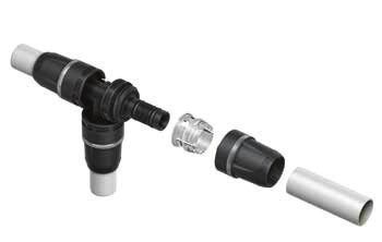
TECElogo - System Description

           System Description                                              TECElogo PE-Xc composite pipe
TECElogo

           TECElogo is a universal installation system for drinking        The TECElogo PE-Xc composite pipe is a pipe with a butt-
           water and heating installations. Composite pipes are avail-     welded aluminium layer and PE-Xc inner pipe. This combi-
           able in dimensions 16 to 63. The connection technology          nation of materials reduces the thermal length change and
           requires no pressing tools. Handling requires only pipe         simultaneously makes the pipe rigid and bend-resistant.
           cutters and a calibrator. The prepared pipe simply slots        The use of PE-Xc means this composite pipe demonstrates
           into the TECElogo connector and the connection is ready.        outstanding creep strength at temperatures up to 90 °C.

           TECElogo offers:                                                                TECElogo PE-Xc inner pipe
           • connection without pressing tools                                              Aluminium layer
           • high pressure and temperature resistance
           • no hygiene issues
           • flush-mounting possible
           • dimensionally stable, bend-resistant composite pipes
           • fittings can be disassembled and reused
           Types of pipe
           The TECElogo composite pipes are available in two ver-
           sions:
           • PE-Xc composite pipe
           • PE-RT composite pipe
                                                                                       Bonding agents
           Advantages of TECElogo composite pipes:
           • universal pipe for drinking water and heating installations   Composition of the TECElogo PE-Xc composite pipe

           • linear extension comparable to a metal pipe                   Delivery forms:
           • visually appealing outer white layer                          • Dimensions 16–63 (16/20/25/32/40/50/63)
           • easy to lay because of its bend-resistant rigidity            • as a roll (up to dim. 25) or in rod form
           • corrosion resistant                                           • in black corrugated pipe sheathing (16/20/25) or
           • resistant to heating inhibitors                               • as pre-insulated variants (16/20/25)
           • external and internal monitoring
           • DVGW certified                                                 Special advantages of TECElogo PE-Xc pipes
           • potential operating pressure 10 bar                           the high mechanical load-bearing capacity gives the
                                                                           electron beam cross-linked TECElogo pipes the following
           TECElogo composite pipes can be used:                           properties:
           • in floor and flat distribution                                  • very good long-term behaviour in internal pressure creep
           • in cellars, rising pipes and surface-mounting                   rupture strength tests, even at higher temperatures
           • in insulation in concealed areas                              • good thermal ageing stability so no damage from ther-
           • in radiator connection                                          mo-oxidative ageing occurs during proper use
           • for underfloor and wall heating, etc.                          • good resilience to the formation of stress fractures
                                                                           • good chemical resistance, which means also resistant to
                                                                             heating water additions, such as e.g. inhibitors
                                                                           • can be cold-laid without heat treatment
                                                                           • good abrasion resistance and tear resistance
                                                                           • impact-resistant at low temperatures
                                                                           • no plastic creep behaviour

           2-4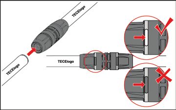
TECElogo PE-RT composite pipe                              Fittings

                                                                                                                             TECElogo
The TECElogo PE-RT composite pipe is a pipe with a butt-   Fittings are available made of red brass, polyphenylsul-
welded aluminium layer and                                 phone (PPSU) as well as brass (with restriction in drinking
                                                           water installations - see below).
PE-RT inner pipe. This combination of materials reduces    Properties and features of TECElogo fittings:
the thermal length change and simultaneously makes         • one fitting (red brass and PPSU) for drinking water and
the pipe rigid and bend-resistant. The use of PE-RT type     heating installations
2 means this composite pipe demonstrates outstanding       • no hygiene issues
creep strength at temperatures up to 90 °C.                • mechanically highly durable

                 TECElogo PE-RT inner pipe                 Red brass
                 Aluminium layer
     Protective white layer

                                                           Universal and future-proof – approved for drinking water
                                                           installations.
             Bonding agents
                                                           The flow-optimised all-round fitting is dimensionally stable
                                                           and resistant to erosion as well as corrosion through dezin-
Composition of the TECElogo PE-RT composite pipe
                                                           cification and stress corrosion cracking. The standardised
Delivery forms:                                            material complies with generally accepted engineering
• Dimensions 16–25 (16/20/25)                              standards and is recommended by the German Federal
• as rolls or in rod form or                               Environment Agency (UBA) for drinking water installations.
• in black corrugated pipe sheathing (16/20/25)            The threaded TECElogo fitting is equally suitable for
                                                           drinking water installations to DIN 1988/DIN EN 806 and
                                                           heating installations.

                                                           PPSU

                                                           The fitting made of high-performance plastic PPSU is
                                                           corrosion-free and impact-resistant. It is equally suitable for
                                                           drinking water installations to DIN 1988/DIN EN 806 and
                                                           heating installations.

                                                                                                                      2-5
TECElogo - System Description
Brass*
TECElogo
The inexpensive metallic alternative to red brass fittings
made of standard brass. The fitting can be used without
restriction for heating installations and with certain limita-
tions for drinking water installations.
The 98/83 Directive on water quality for human con-
sumption set out by the European Community defines a
maximum lead content of 0.01 mg/l. Of this, the maximum
amount permitted to emanate from the drinking water
installation is 0.005 mg/l. To ensure reliable compliance
with the limit value, TECE recommends using red brass,
standard brass or PPSU fittings. These three materials are
included on the positive list of the German Federal Envi-
ronment Agency (UBA).
* Please note that some qualities of drinking water may have a corrosive
effect on metals. We recommend checking the selection of the mate-
rial (see technical data section of the tube and the charts on following
pages).
TECElogo connection
A TECElogo connection is very compact and consists of
just a few components:
3
2
1 4
1. Base body – material either:
a) universal red brass
b) high-performance PPSU
c) special brass resistant to dezincification
2. Collet - made of fibre-reinforced polyamide
3. Clamping ring made of PPSU - holds the pipe safely
on the base body
4. O-rings - ensure a permanently tight connection
2-6Application limits TECElogo system pipes PE-RT composite pipes
TECElogo
The TECElogo system is classified according to the appli- Pipe designation PE-RT/Al/PE PE-RT/Al/PE PE-RT/Al/PE
cation type. Suitable for drinking water installations in Dimension 16 20 25
accordance with application class 2 and for heating instal- Delivery length – roll in m 100 100 50
lations in accordance with application class 5. See also
Rods (m)
table “Classification of operating conditions ISO 10508” 100 70 45
(5 m/pipe)
TWA, HKA, TWA, HKA, TWA, HKA,
Field of application*
It has a lifespan of more than 50 years. The assessment is FBH FBH FBH
carried out using a standardised temperature group based Application class/ operating 2 / 10 bar 2 / 10 bar 2 / 10 bar
pressure 5 / 10 bar 5 / 10 bar 5 / 10 bar
on real operating temperatures. The TECElogo range
contains two qualities of pipe. The pipes differ in the plastic Approval DVGW DVGW DVGW
that makes up the inner pipe: Colour white white white
• PE-Xc Outside diameter in mm 16 20 25
• PE-RT Wall thickness in mm 2 2.25 2.5
Inside diameter in mm 12 15.5 20
Both pipe qualities are tested and DVGW certified with the Available in corrugated
yes yes yes
TECElogo push-fittings. They fulfil the requirements for protective pipe
class 2 (hot drinking water) and class 5 (heat) in accord- Can be delivered with 9 mm
-- -- --
ance with ISO 10508. insulation h = 0.040 W/(m . K)
Can be delivered with 13 mm
-- -- --
The following applies for TECElogo composite pipes: insulation h = 0.040 W/(m . K)
• must not be used in solar plants Pipe weight empty in kg/m 0.10 0.14 0.20
• unregulated hot water boiler must not be connected Internal volume in dm³/m 0.11 0.19 0.31
directly. A metal pipe of at least 1 m must be installed Pipe roughness in mm 0.007 0.007 0.007
between the TECElogo and the hot water boiler. Thermal conductivity
0.41 0.41 0.41
• Suitable measures should be taken with solid fuel boilers uninsulated in W/(m² . K)
to ensure that the temperatures permitted in accordance Coefficient of thermal
0.026 0.026 0.026
with ISO 10508 are not exceeded. expansion in mm/(m . K)
• No contact with open flames Minimum bending radius
in mm
- without bending spring 80 100 125
- with bending spring 64 80 100
* TWA – drinking water system; HKA – radiator connection;
FBH - floor heating;
Technical data of TECElogo PE-RT composite pipes.
2-7TECElogo - System Description
TECElogo system pipes PE-Xc composite pipes*
TECElogo
Pipe designation PE-Xc/Al/PE
Dimension 16 20 25 32 40 50 63
Delivery length – roll in m 100 100 50 -- -- -- --
Rods (m) (5 m/pipe) 100 70 45 30 15 15 5
Field of application* TWA, HKA, FBH
Application class/ operating pressure 2 / 10 bar; 5 / 10 bar
Approval DVGW
Colour white
Outside diameter in mm 16 20 25 32 40 50 63
Wall thickness in mm 2 2.25 2.5 3 4 4.5 6
Inside diameter in mm 12 15.5 20 26 32 41 51
Available in corrugated protective pipe yes yes yes -- -- -- --
Can be delivered with 6 mm insulation h
yes yes yes -- -- -- --
= 0.040 W/(m . K)
Can be delivered with 9 mm insulation h
yes yes yes -- -- -- --
= 0.040 W/(m . K)
Can be delivered with 13 mm insulation
yes yes yes -- -- -- --
h = 0.040 W/(m . K)
Pipe weight empty in kg/m 0.10 0.14 0.21 0.33 0.53 0.79 1.22
Internal volume in dm³/m 0.11 0.19 0.31 0.53 0.80 1.32 2.04
Pipe roughness in mm 0.007
Thermal conductivity uninsulated in W/
0.43
(m² . K)
Coefficient of thermal expansion
0.026
in mm/(m . K)
Minimum bending radius in mm
- without bending spring 80 100 125 160 200 250 315
- with bending spring 64 80 100 -- -- -- --
* TWA – drinking water system; HKA – radiator connection; FBH – floor heating;
Technical data of TECElogo PE-Xc composite pipes
Calculation Operating Operating Operating
Application Tmax Tmal
temperature TD periodb with TD period with Tmax period with Tmal Typical application area
class °C °C
°C Years a Years Hours
1a 60 49 80 1 95 100 Hot water supply (60 °C)
2a 70 49 80 1 95 100 Hot water supply (70 °C)
20 0.5
3c 30 20 50 4.5 65 100 Low-temperature floor heating
40 25
20 2.5
Floor heating and
4b 40 20 70 2.5 100 100
low-temperature radiator connection
60 25
20 14
5b 60 25 90 1 100 100 High-temperature radiator connection
80 10
TD = temperature the pipe system is designed for. Tmax = maximum temperature permitted for a short time
Tmal = highest possible temperature that may be reached in the event of the fault “mal” (maximum 100 hours in 50 years)
a
A state can select either class 1 or class 2 according to its national provisions.
b
If there is more than one operating temperature for the operating duration and the associated temperature for an application class, the
corresponding operating duration times should be added. "Plus cumulative" in the table implies a temperature group for the temperature given
for an operating period (e.g. the temperature group for a period of 50 years for class 5 is made up as follows: 20 °C over 14 years, followed by 60
°C over 25 years, followed by 80 °C over 10 years, followed by 90 °C over 1 year, followed by 100 °C over 100 h).
c
Only permitted if the fault temperature cannot exceed 65 °C.
Classification of operating conditions (in accordance with ISO 10508)
2-8TECElogo - Areas of application
Areas of application Measures for Legionella prophylaxis
TECElogo
Drinking water installations must be planned, designed
Drinking water installation
and operated with special care in accordance with DIN
Drinking water presents special requirements for an instal- EN 806 and DIN 1988; VDI 6023 and DVGW worksheet
lation system. It’s a consumable and must not be nega- W551 also apply.
tively impacted by the installation system materials. The
planning and design as well as the operation of drinking The risk of Legionella formation can be minimised by com-
water installations must be carried out in accordance with plying with a few simple rules:
DIN 1988, DIN EN 806, DIN EN 1717/A1 and VDI 6023. • Unnecessary and dead pipe sections where water can
The fitter has to make sure that they are installing a piping stagnate should be immediately disconnected at the
system that corresponds to the applicable recognised outlet.
technical regulations. The TECElogo is DVGW certified and • Care should be taken during installation to ensure no dirt
proven suitable for drinking water installations. Among is introduced into the piping system
other things, the DVGW certification includes: • the storage water volume should be designed to be as
• technical inspection of the components small as possible.
• KTW inspection • Pipes should be selected in the correct dimensions.
• Certification in accordance with worksheet DVGW W270 • Circulation pipes must not be designed to be too large.
• Circulation pipes must be hydraulically balanced.
Field of application
• The temperature of the hot water boiler must be at least
The TECElogo system is suitable for all drinking water
60°C.
qualities in accordance with DIN 50930 Section 6,
• The circulation return must not fall below 55 °C.
which comply with the current Drinking Water Ordinance
• The system should be rinsed particularly thoroughly
(TrinkwV 2011), DIN 2000 and EU Council Directive 98/83/
during commissioning.
EG dated 3rd November 1998.
• No organic materials such as e.g. hemp should remain in
the drinking water installation.
The following components are available for drinking water
• Uninsulated sections of the hot water line should be
installations:
avoided.
• plastic fittings made of PPSU
• Care should be taken to ensure the correct function and
• flow-optimised metal fittings made of red brass
maintenance of water treatment systems and filters.
• composite pipes with PE-Xc or PE-RT inliners
• A local hot water supply should be installed if tapping
All materials are recommended by DVGW and recognised
points are far away or used very rarely.
across Europe. All metallic components in the TECElogo
• If cold water lines are located next to hot water lines or
that come into contact with water comply with the evalua-
heating pipes, they have to be insulated well, so that the
tion principles (as at 19/01/2016) of the German Federal
cold water cannot heat up.
Environment Agency (UBA) as per the 4MS material list (as
• Lines carrying cold water should not be laid in hollow
at 05/01/2017).
spaces in which circulation and heating lines are located.
Material selection • For hygiene reasons, pressure tests should not be per-
The fitter has satisfied their duty of care when they formed with water but rather oil-free compressed air or
• have presented the drinking water analysis as per DIN inert gas. Pressure tests with water are only permitted
50930-6 for the supply area of the building project to immediately prior to the commissioning of the installa-
be constructed and have inspected the suitability of the tion. Only drinking water with no hygiene issues should
TECElogo system, be used for rinsing and the pressure test.
• have satisfied themselves of the supplier’s experience,
• if necessary, receive approval for TECElogo from TECE.
2-9TECElogo - Areas of application
Disinfection of drinking water installations Chemical disinfection
TECElogo
The suitability of the TECElogo system for drinking water Chemical disinfection measures should be carried out in
is confirmed by the DVGW certification. The components compliance with DVGW worksheet W 291. Care should
of the TECElogo system are made from materials recog- be taken that the active ingredients, concentrations,
nised and valued across Europe. A drinking water installa- usage periods and maximum temperatures listed here are
tion planned, designed and operated in accordance with complied with. The combination of thermal and chemical
DIN 1988, DIN EN 806, DIN EN 1717/A1 and VDI 6023 disinfection is not permitted. The water temperature during
has no hygiene issues and in principle requires no disin- chemical disinfection must not exceed 25 °C.
fection measures. Disinfection is only necessary in excep-
tional instances and only then to be carried out if there is The TECElogo system can be disinfected using the dis-
an urgent requirement (contamination). infection agents listed in DVGW worksheet W 551. The
dosages must not be exceeded. It should be ensured that
This is to be viewed as an immediate emergency measure nobody draws drinking water during the disinfection pro-
in order to return the drinking water installation to a usable cess. Following chemical disinfection it MUST be ensured
state. The cause of the microbial contamination - e.g. con- that all disinfection agent residues have been sufficiently
struction fault or incorrect operation - must be eliminated. rinsed out of the piping network. The water containing the
The maintenance of the usability of the drinking water disinfection agent must not be added to the drainage.
installation by repeated disinfection measures must be
avoided. In such instances, remodelling works take priority Prior to carrying out disinfection measures with chemi-
over disinfection measures. cal agents it should be ensured that all components of
Repeated courses of disinfection have a negative impact the drinking water installation are resistant to the agent.
on the lifespan of the installation. Special attention should be given to stainless steel com-
ponents. The provisions of DVGW worksheet W 551 must
A fundamental distinction is to be made between meas- be observed. The manufacturer of the disinfection agent
ures outside of ongoing operation (chemical disinfection) must approve the suitability of the agent for use with PE-Xc
and measures in ongoing operation (thermal disinfection pipes and red brass. The manufacturer’s specifications
and continuous chemical disinfection). must be observed.
Thermal disinfection The disinfectant effect of the chemical disinfection agent
DVGW worksheet W551 prescribes a three-minute flush- normally results from the oxidative effect of the contents.
ing of each tapping point with hot water at a minimum Regular disinfection means the materials that comprise
temperature of 70° C. It has been proven in practice that the drinking water installation could also be attacked.
the hot water boiler should be heated to 80 °C to com- Repeated courses of chemical disinfection have a sig-
pensate for the temperature losses to the tapping points. nificant negative impact on the lifespan of the TECElogo
Before rinsing the tapping points any existing circulation system. The total number should thus be restricted to five
(if present) must be switched on until the circulation line disinfection cycles over the total lifespan of the pipes.
reaches a minimum of 70 °C. Check that no users could Repeated disinfection measures do not conform to the
scald themselves during the thermal disinfection. All state of the technology. A disinfection measure is only
drinking water installation pipes from the TECElogo system warranted in order to return a drinking water installation to
can be promptly disinfected using this method. Restriction a usable state following contamination.
of the lifespan of the TECElogo pipes cannot be ruled out
where thermal disinfection is used regularly and consider-
ation should be given to renovation of the drinking water
installation.
2-10Agent Form of delivery Storage General safety infor- Max. concen- Effect duration Maximum tempera-
TECElogo
mation * tration ture permitted
Hydrogen perox- Watery solution in var- Away from light, cool, Protective gear 150 mg/l H2O2 Max. 24 h Tmax ≤ 25 °C
ide H2O2 ious concentrations avoid all contamina- required for solutions
tion >5%
Sodium hypochlo- Watery solution with Away from light, Alkaline, irritant, 50 mg/l chlorine Max. 12 h Tmax ≤ 25 °C
rite maximum 150 g/l cool, sealed and in a poisonous, protective
chlorine collection tray gear required
Chlorine dioxide Two components: Away from light, cool Oxidative effect, do 6 mg/l ClO2 Max. 12 h Tmax ≤ 25 °C
ClO2 sodium chlorite, and sealed not inhale chlorine
sodium peroxide dioxide has, protec-
sulphate tive gear required
* The corresponding notes in the manufacturer’s safety datasheets must be observed.
** This value must not be exceeded over the total usage period at any point in the installation.
Chemical disinfections, agents and concentrations in accordance with e.g. DVGW W 557
Continuous chemical disinfection
Disinfection of a contaminated drinking water system
over a constant given dose of disinfection agents is not
expedient according to today’s knowledge. It should there-
fore only be carried out in rare exceptional cases. Here it
should be ensured that the requirements of the current
Drinking Water Ordinance and the UBA list in accordance
with Sec. 11 DWO (TVO) are met. The prescribed limit
values would have to be exceeded significantly in order
to achieve a relevant effect, however. Continuously added
disinfection agents can have a significant effect on the
lifespan of the drinking water installation. This kind of disin-
fection is advised against due to possible material deterio-
ration. No guarantee can be made in these cases.
Heating installation
The TECElogo system is approved for heating installations.
The following components are available for this:
• plastic fittings made of PPSU
• metal fittings made of DR brass or red brass
• composite pipes made of PE-Xc and PE-RT for system
temperatures up to 90 °C in accordance with ISO 10508
• connection accessories/transitions made of copper
The aluminium layer on the TECElogo composite pipe
makes it 100% oxygen-tight.
2-11TECElogo - Connection Technology
Connection technology TECE provides two toolsets. These system tools let you
TECElogo
create and undo connections for dimensions 16 to 25 and
TECElogo is a secure and quick push-fitting system for
32 to 63.
composite pipes, making a connection with this is very
simple:
Tool for dim. 16–25:
1. Cut pipe to length
• TECElogo pipe cutters (to dim. 25)
2. calibrate and mill
• TECElogo calibration and chamfering tools
3. push it in - and you’re done.
• TECElogo disassembly tools
The connection is sealed using two sturdy O-rings. The
Tool for dim. 32–63*:
conical shape of the retaining claw makes it easier to slide
• TECE pipe cutters (dim. 16–63)
the pipe in and prevents the connection from coming
• TECElogo calibration and chamfering tools
undone. It holds the pipe secure and tight - without dam-
• TECElogo disassembly tools
aging it.
The closed inspection window allows you to check the
Create connection
insertion depth and enables the fitter to be certain of a
secure connection. The following work steps must be followed to ensure a
correct TECElogo connection:
Handling
Important note: TECElogo must be processed only with the Cut pipe to length
accompanying system tools. The use of tools that are not
part of the system is not permitted!
It is not permitted to connect TECElogo components with
third-party pipes or fittings. A warranty claim can only be
made for the possible applications outlined in the System
Description.
For cutting a TECElogo pipe to length use TECE pipe cut-
ters (order no. 8760002) for the smaller dimensions (up to
25), and use the TECE pipe cutter (order no. 8760008) for
the larger dimensions (up to 63)
Cut the pipes at a right-angle. Do NOT use a saw or similar
tools!
Note: TECElogo pipes may only be processed using the
TECE system tools in perfect condition. In particular, the
cutter or the cog must be sharp and without burrs - this/
these can be replaced if necessary.
Toolbox containing pipe cutters, calibration and chamfering tool as well as disas-
sembly tools
2-12Clean calibrator
TECElogo
Correctly calibrated pipe
The TECElogo calibrator must be dirt-free. Clean the cali-
bration and chamfering tool after every calibration (“free
blowing”). Residual shavings could otherwise be trans-
ferred into the sealing zone on the connector.
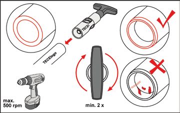
Calibrate and chamfer pipe
Incorrectly calibrated pipe
The pipe can also be calibrated using a cordless screw-
driver. The number of revolutions here must not exceed
500 per minute (500 rpm) however (= level 1).
Pipe insertion and visual check
Place the calibration and chamfering tool matching the
pipe dimensions (order no. 87600xx) on the end of a
TECElogo pipe and turn clockwise multiple times.
The pipe should then have - inside and out - an even
chamfer and be free of burrs. There must be no shavings
left on the chamfer, which should be visually checked fol-
lowing calibration (see subsequent photos). In the event of
damage (e.g. serrations), the damaged end must be cut off
and the pipe recalibrated.
Check the fitting for dirt and clean or swap if necessary. To
avoid dirt, do not remove the hygiene caps of the fitting
until immediately before the push-fitting operation. Simply
push the TECElogo pipe into the fitting until it reaches the
stop.
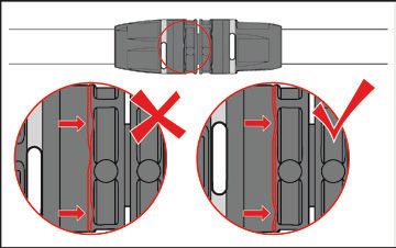
The connection is only completed correctly once the pipe
is visible in one of the inspection windows.
2-13TECElogo - Connection Technology
If a visual check via the inspection window is not possible The following working steps are necessary in order to
TECElogo
(e.g. in poor lighting), mark the push-in depth on the pipe. undo and re-establish a connection:
The pipe must then be pushed in up to this marker.
The spacing between the markers to the pipe end depend Mark and disconnect the collet
on the dimensions of the pipe:
Dimension Marker spacing
in mm
16 27
go
E lo
20 32 EC
T
25 35
32 46
40 48
50 48
63 55
go
Marker spacing from pipe end E lo
T EC
Check the finished TECElogo push-fitting connection by
trying to pull it apart: You must not be able to pull the pipe Before undoing a connection, make a continuous mark-
from the fitting. ing on the collet and threaded clip. Fix the fitting with the
disassembly open-end wrench and unscrew the collet with
the dismounting key.
Remove the fitting from the pipe and reattach
Undo connection and connect again
You can undo the TECElogo system connections if
required. With new installations all disconnected parts can
be reused. With connections that are only disconnected
Now push back the collet and clamping ring and pull the
after a TECElogo installation has been connected, the
pipe away from the fitting base body, then remove the
used pipe ends and O-rings must be replaced but the fit-
clamping ring and collet from the pipe.
ting base body, collets and clamping rings can be reused,
Before assembling the fitting, check the base body and
however. Additionally, only original TECElogo O-rings
remove any dirt or chips. If the O-ring is damaged, it must
should be used - these are available as spare parts.
be replaced.
Note: Only the disassembly tool from the TECElogo system
must ever be used for undoing and re-connecting.
2-14A. For new installation:
TECElogo
Place the clamping ring on the support with the conical
end facing the pipe and tighten by hand with the collet.
Then screw the collet on using the disassembly tools
tightly enough that the collet noticeably “clicks” into the
end position (see following figure) and the markers once
again match.
B. After commissioning:
Slide the new O-rings onto the fitting. Place the clamping
ring on the support with the conical end facing the pipe
and tighten by hand with the collet. Then screw the collet
on using the disassembly tools tightly enough that the
collet noticeably “clicks” into the end position and the
markers once again match.
The subsequent steps - cut, calibrate and chamfer pipe,
push it in and conduct visual check - are carried out as
outlined in the previous section “Create connection”.
2-15TECElogo - Installation Guidelines
Installation Guidelines they maintain a certain distance and the space around the
TECElogo
lines can be filled in with sand. These protective measures
For the installation of heating and drinking water instal-
should be checked once again before the poured asphalt
lations, the applicable technical rulings, standards and
is actually applied in order to avoid irreparable damage to
provisions should be observed. Installations must only be
the piping system. During the application of the asphalt the
carried out by specialist companies.
pipes should be flushed with cold water.
Avoidance of air pockets
General notes
Pipes must be laid such that it no air pockets can form. At
The following information should be considered when
the deepest point in the system there must also be a facil-
using TECElogo pipes.
ity for draining the pipeline.
Threaded connections
Protection against UV radiation
For threaded connections TECE recommends the use of
UV radiation damages the TECElogo pipes over longer
hemp combined with a sealant paste approved for this
periods of time. The pipe packaging offers sufficient pro-
purpose. Using too much hemp can cause damage to the
tection against UV radiation but is not weather-proof. The
internal and external threaded components. Care should
pipes should therefore not be stored out in the open. The
be taken to ensure no hemp residue remains in the pipe
pipes should not be exposed to sunlight for unnecessary
system. If other thread sealants are used, the warranty
amounts of time. They should be protected against UV
must be assumed by the sealant manufacturer.
light where necessary. TECElogo pipes laid in the open
Processing temperatures must be protected against sunlight in a black corrugated
The TECElogo system can be handled down to a minimum pipe.
temperature of 0 °C. With lower temperatures, the ends of Identification of pipelines
the pipe should be warmed up until “lukewarm”. The use of
TECE recommends identifying installation pipes in accord-
open flames is also prohibited!
ance with DIN 2403.
Coating of fittings
Installation on bitumen sheets
TECElogo fittings must be fundamentally protected from
TECElogo pipes must be completely dried before laying
contact with the wall structure, plasterboard, cement,
these on bitumen sheets or coatings containing solvents.
screed, rapid binders or similar using suitable coverings.
The manufacturer’s setting times should be observed.
Direct contact with the structural shell must be avoided
at all costs owing to the sound insulation requirements in Arrangement of pipelines
accordance with DIN 4109 and VDI 4100. If cold and hot water pipes are laid on top of one another,
the pipes carrying hot water must be laid above the cold
Kinks and deformities
water line.
If a TECElogo pipe develops a kink or deformation due to
incorrect handling or unfavourable construction site condi- Contact with solvents
tions then the site of the deformation must be repaired or Direct contact between TECElogo components and sol-
an elbow fitting equipped for tight radii. vents or solvent-based paints, dyes, sprays, adhesive
strips, etc. should be avoided. Solvents can erode the
Use with poured asphalt
plastic components in the system.
The high temperatures than can occur with the application
of poured asphalt (approx. 250 °C) would destroy the pipe-
line immediately on direct contact. This also applies to the
use of pipe-in-pipe systems. Suitable protection measures
should therefore be taken. The pipe-in-pipe lines installed
on the bare concrete are sufficiently protected against
burning when the insulating fibreboards used during
work with poured asphalt are laid over the pipes before
the asphalt is applied. What is particularly critical is not
the open floor areas, however, but the locations at which
the lines are guided from the bare concrete into the wall
structure. Here the lines are optimally protected when the
edge insulation strips are laid in front of the lines so that
2-16Potential equalisation
TECElogo
TECElogo composite pipes may not be used as earthing
conductors for electrical systems in accordance with VDE
Dim.
0100. .
im
This means metal pipe installations exchanged in part for xd
5
a pipe from the TECElogo range (e.g. during renovations)
should be checked for correct earthing.
Protection against frost
Filled TECElogo pipes should be protected against frost.
The TECElogo system is suitable for the following frost
protection agents and concentrations:
* without bending spring; 4 x dim. with bending spring.
• Ethyl glycol (Antifrogen N): May be used up to a concen-
Minimal bending radius of TECElogo composite pipes
tration of maximum 50%. TECE recommends restrict-
ing the concentration to 35%. A concentration of 50 %
Antifrogen N corresponds to frost protection down to a Dimension Minimum bending radius in mm
temperature of -38 °C. A concentration of 35 % Antifro- - without bending spring with bending spring
gen N corresponds to frost protection down to -22 °C. If 16 80 64
Antifrogen N is dosed above 50%, the frost protection 20 100 80
effect is reversed. Slurry ice formed at temperatures 25 125 100
below -25 °C. 32 160 --
• Propylene glycol: May be used up to a concentration of 40 200 --
maximum 25%. Propylene glycol is primarily used in the 50 250 --
foodstuffs industry. A concentration of 25% corresponds 63 315 --
to frost protection down to -10 °C. Overdosing with Bending radii of TECElogo pipes
propylene glycol can lead to stress fractures in the PE-RT
material.
Heat tracings
Heat tracings as well as self-regulating heater bands
approved by manufacturers for plastic piping systems in
the sanitary sector can be used for TECElogo. To ensure
optimum heat transfer the heating bands are attached
to the TECElogo installation pipe across their full surface
using broad aluminium adhesive strips. The manufacturer’s
instructions should be followed.
Bending radii
TECElogo composite pipes can be bent by hand up to Bending radii without bending springs (left) and using bending springs (right)
dimension 25, but commercially available bending tools
Pipes that have already been push-fitted should not be
must be used from dimension 32.
subsequently bent. If you do need to do this, make sure
The pipes can be bent in the neutral line with a minimal
that the pipe has been pushed onto the fitting straight and
bending radius - in principle corresponding to 5x the
without tension. Tension can lead to leaks.
dimension of the pipe - to avoid buckling and kinks.
If bending springs are used during the installation of TECE-
logo pipes then the minimal bending radius - to 4x the
dimension of the pipe - may be reduced:
2-17TECElogo - Installation Guidelines
Thermal length changes Determining the length of the bending leg
TECElogo
Materials expand when heated and contract when cooling The bending leg length (b) can be found in the following
down. The systemic, huge temperature differences mean diagram:
that the lines in hot water and heating installations must Dim. 14 16 20 26 32 40 50 63
30
be attached such that the length extension in elbows or
25
special compensating elbows can be balanced out.
Length extension [mm]
20
Detecting thermal length changes
15
Thermal length changes are detected using the following
formula: 10
6l = _ · l · 6t
6l thermal length change of the pipe in mm
5
_ expansion coefficient of the TECElogo pipes 0 200 400 600 800 1000 1200 1400
l starting length of the pipe in m
6t temperature difference in K* Bending leg length b [mm]
* K = Kelvin is the SI base unit of temperature and relates Bending leg length for TECElogo pipes
to absolute zero. The pipe lengths to be observed can be isolated using
(0 °C = 273.16 K) fixed and sliding clamps.
Expansion coefficient of the TECElogo pipes:
Composite pipes _ = 0.026 mm/(mK)
Example: A 12 metre-long TECElogo heating line made
of composite pipe is installed at 5 °C in winter. Operating
conditions can lead to a temperature of 70 °C.
l 12 m b Bending leg length
6t 70 K - 5 K = 65 K I Pipe length
F Fixed clamp
_ 0.026 mm/mK G Sliding clamp
6l = 0.026 mm/mK · 12 m · 65 K = 20.28 mm
Result: The pipe will expand by approx. 20 mm. The expan-
sion must be compensated for via structural conditions.
Alternatively, the thermal length extension can be found in
Compensation of thermal linear extension in a direction change
the following diagram.
It can happen that the planned pipe design does not offer
sufficient room for movement for the inclusion of thermal
Pipe length [m]
Length change [mm]
linear extension. In this case, compensating bends should
be included in the plan that take into account the bending
leg lengths.
Temperature difference [K] b Bending leg length
I Pipe length
Thermal length extension for TECElogo composite pipes
F Fixed clamp
G Sliding clamp
Compensation of thermal linear extension in an extension loop
2-18Example: The pipe length extension in the aforementioned Routing of water-bearing TECElogo lines
TECElogo
example is approx. 20 mm. The bending leg length b can
The routing of TECElogo installation lines must comply
be found in the aforementioned diagram. For a TECElogo
with the recognised rules of engineering. The quality of
pipe with a dimension of 20 mm this results in a value
the drinking water must not be negatively affected by the
of 670 mm. If a sliding clamp of at least 670 mm is fitted
conduit.
to the elbow then no additional compensating elbow is
required. TECElogo lines on plaster
Special installation notes for linear extension The type and spacing of the attachment depend on the
construction conditions on site. The fixing of the pipelines
• Take care to ensure sufficient “room to manoeuvre”
should be carried out using static perspectives taking into
when connection radiators from the floor or wall in order
consideration the filled and insulated pipes according to
to include linear extension.
the recognised rules of engineering.
• The connection should always be guided to the radiators
in an elbow design.
TECElogo Attachment spacing
• TECElogo fittings should be installed tension-free. If nec-
dim. in m
essary, suitable attachments should arranged to decou-
16 1
ple the fittings from the influence of the length extension.
20 1.15
25 1.3
Radiator 32 1.5
40 1.8
50 2.0
63 2.0
Attachment distances for TECElogo lines installed on plaster
TECElogo Pipe weight empty
Manifold dim. in kg/m
16 0.21
Example installation taking into account linear extension 20 0.34
25 0.52
32 0.86
Attaching conduit
40 1.33
TECElogo pipelines are only to be attached using the
50 2.09
approved pipe clips for the relevant purpose. Commer-
63 3.26
cially available wall plugs can be used to attach clamps Pipe masses TECElogo
as long as they are used on components with sufficient
mechanical stability. The TECElogo pipelines may not be The pipes should be laid so that they cannot be affected
attached to other lines. by moisture from other fittings such as drips or condensa-
tion.
Concealed TECElogo lines
Depending on the wall composition or quality of the
masonry, the thermal length extension of a concealed
TECElogo composite pipe can cause damage to the wall.
TECE therefore recommends that all concealed TECElogo
composite pipes be fitted with pipe insulation. The pre-in-
sulated TECElogo pipes (only PE-Xc) fulfil this requirement.
Alternatively, if no thermal insulation is required, the
composite pipes can be laid in corrugated pipe sheathing.
These pipes are also part of the TECElogo range.
TECElogo fittings must be fundamentally protected from
contact with the wall structure, plasterboard, cement,
screed, rapid binders or similar using suitable coverings.
2-19TECElogo - Installation Guidelines
Direct contact with the structural shell must be avoided Piperun in floor structures
TECElogo
at all costs owing to the sound insulation requirements in For planning and laying of pipes in floor structures, the
accordance with DIN 4109 and VDI 4100. screed trade has described in the guideline titled “Pipes,
TECElogo lines in concrete or screed cable and cable channels on unfinished floors” how
piperuns have to be carried out: “Pipelines in the floor
The pipes are solidly enclosed by concrete or screed so
assembly must be installed free of junctions, in straight
that the linear extension of the pipe material occurs on the
lines as well as axially parallel and parallel to the wall. Even
inside. Special measures to include thermal linear exten-
as early as the planning stage heating and drinking water
sion are unnecessary in this instance. If the pipes are laid
lines should already take priority over electrical lines and
in the insulation layer between concrete and screed, how-
conduits should be removed.”
ever, they should be arranged so that the expected linear
• The pipelines in a pipe route must be grouped together
extension is compensated by the insulation or a pipe guide
as tightly as possible.
laid inside the elbow.
• The pipe route containing lines laid in parallel inclusive
Heat insulation and impact sound requirements must be
of pipe insulation may be a maximum of 30 cm
met. The corresponding standards and guidelines must be
adhered to. It is therefore advisable to install the TECElogo
wide.
pipes in a suitable levelling course. The additional instal-
• The space between the individual lines should adhere to
lation height must be considered during planning. The
a minimum distance of 20 cm. The minimum distance of
fittings must be protected against corrosion.
a line to a wall is 20 cm.
TECElogo pipes installed on bare floor surfaces or in con-
• The dimensions given above should be adhered to as
crete ceilings should be attached at a maximum distance
closely as possible next to manifold housings.
of one metre. It should be ensured that the TECElogo
• Around the door the distance from the door jamb should
pipes installed on bare floor surfaces are not damaged
be a minimum of 10 cm.
by ladders, equipment, wheelbarrows, constant impacts
Pipes of different thicknesses or other fittings within the
or similar. The pipelines must be inspected immediately
line must be balanced to create an even surface for the
before the screed is laid.
impact sound insulation.
TECElogo lines guided through movement joints
If pipelines are guided through building expansion joints,
these must be laid in corrugated pipe sheathing. The cor-
rugated pipe sheathing must sit at least 25 cm above the
movement joint on all sides. Thermal insulation with a wall
thickness of at least 6 mm may be used as an alternative
to corrugated piping.
2-20TECElogo - Planning and design
Sound insulation Planning and design
TECElogo
The noise behaviour of a drinking water heating installa- Dimensioning of drinking water systems
tion in relation to the building structure should be taken
into consideration during the planning and implementation. The planning and installation of drinking water systems are
governed by local legislation, standards and guidelines.
The requirements for sound insulation are governed by Hygiene requirements
local legislation, standards and guidelines. A drinking water installation must ensure that the water
at the tapping point meets the requirements of the Drink-
Sound-insulated installation of the TECElogo system ing Water Ordinance. All metal fittings intended for use
For water-bearing pipelines, special attention should be with drinking water are only composed of materials that
paid to structure-borne noise. The installation therefore comply with the UBA’s metal evaluation principles (as at
has to be mounted so as to be decoupled from the build- 17/03/2017) or the 4MS materials list (as at 05/01/2017).
ing structure: The biological suitability of the TECElogo system is con-
• Use of pipe attachments that insulate against struc- firmed by the DVGW approval. The technical measures
ture-borne noise. to be taken to reduce the growth of Legionella as well as
• Pipes passed through screed or in walls must be the planning, operation and restoration of drinking water
equipped with at least 9 mm of insulation. The TECElogo systems are described in the DVGW worksheet W 551.
range offers appropriately pre-insulated pipes. Corru- Hydraulic design
gated sheath pipes as coverings do not offer sufficient Dimensioning and planning of drinking water lines with
sound insulation. TECElogo is based on local legislation, standards and
• Dry-wall pre-wall installations such as TECEprofil, for guidelines. The necessary product-specific information can
example, offer better sound insulation for sanitary items be found in the following figures and tables.
mounted directed on the wall because they are decou- The first table shows the loss values for TECElogo fittings.
pled from the building structure.
• Drinking water and heating installations must only be
installed on correspondingly solid walls with a weight of
at least 220 kg/m².
• The resting pressure should not exceed 5 bar.
• The permitted through-flow values of fittings should be
adhered to.
• Water-bearing pipes should not - if possible - be installed
on walls connected to rooms requiring protection.
Fire protection
The corresponding local laws, standards and guidelines
on fire protection as well as the generally recognised state
of the art should be observed and adhered to during the
installation.
2-21TECElogo - Planning and design
Item Moulded part Dimension
TECElogo
16 20 25 32 40 50 63
1 Pipe 2.3 1.6 1.3 0.9 0.7 0.7 0.6
2 Coupling 3.9 3.6 1.2 3.4 2.0 0.9 0.8
3 reduc. Coupling (1 dimension) – 3.9 3.7 1.7 3.6 2.0 1.8
4 Elbow 90 °C 22.8 14.6 7.0 13.7 7.9 5.5 5.6
5 Tee any – Through-type 4.4 4.5 1.5 4.0 2.2 1.1 1.0
6 Tee any – Outlet 13.9 14.7 6.9 13.4 7.9 5.3 5.8
7 Tee any – Manifold 15.2 15.1 7.6 14.1 8.2 6.0 5.9
Zeta values [ ] for TECElogo moulded parts (where v=2 m/s)
Item Moulded part Dimension
16 20 25 32 40 50 63
1 Pipe 1.0 1.0 1.0 1.0 1.0 1.0 1.3
2 Coupling 1.7 2.3 0.9 3.8 2.9 1.3 1.7
3 reduc. Coupling (1 dimension) – 2.4 2.8 1.9 5.1 2.9 3.9
4 Elbow 90 °C 9.9 9.1 5.4 15.2 11.3 7.9 12.2
5 Tee any – Through-type 1.9 2.8 1.2 4.4 3.1 1.6 2.2
6 Tee any – Outlet 6.0 9.2 5.3 14.9 11.3 7.6 12.6
7 Tee any – Manifold 6.6 9.4 5.8 15.7 11.7 8.6 12.8
Equivalent pipe lengths [m] for TECElogo moulded parts (where v=2 m/s)
2-22Pressure loss tables in the drinking water installation – Dimensions 16/20/25 mm
TECElogo
TECElogo composite pipes – Pressure losses due to pipe friction in drinking water lines
Dim. 16 Dim. 20 Dim. 25
Water speed V m R V m R V m R
hPa/m hPa/m hPa/m
m/s l/s kg/h mbar/m l/s kg/h mbar/m l/s kg/h mbar/m
0.10 0.011 40.7 0.3 0.019 67.9 0.2 0.031 113.1 0.1
0.20 0.023 81.4 0.6 0.038 135.9 0.6 0.063 226.2 0.4
0.30 0.034 122.1 1.7 0.057 203.8 1.2 0.094 339.3 0.9
0.40 0.045 162.9 2.8 0.075 271.7 2.0 0.126 452.4 1.4
0.50 0.057 203.6 4.1 0.094 339.6 2.9 0.157 565.5 2.1
0.60 0.068 244.3 5.6 0.113 407.6 4.0 0.188 678.6 2.9
0.70 0.079 285.0 7.3 0.132 475.5 5.2 0.220 791.7 3.8
0.80 0.090 325.7 9.2 0.151 543.4 6.6 0.251 904.8 4.8
0.90 0.102 366.4 11.2 0.170 611.4 8.1 0.283 1017.9 5.9
1.00 0.113 407.2 13.5 0.189 679.3 9.8 0.314 1131.0 7.1
1.10 0.124 447.9 16.0 0.208 747.2 11.6 0.346 1244.1 8.4
1.20 0.136 488.6 18.6 0.226 815.1 13.5 0.377 1357.2 9.8
1.30 0.147 529.3 21.4 0.245 883.1 15.5 0.408 1470.3 11.3
1.40 0.158 570.0 24.4 0.264 951.0 17.7 0.440 1583.4 12.9
1.50 0.170 610.7 27.6 0.283 1018.9 20.0 0.471 1696.5 14.5
1.60 0.181 651.4 31.0 0.302 1086.9 22.4 0.503 1809.6 16.3
1.70 0.192 692.2 34.5 0.321 1154.8 25.0 0.534 1922.7 18.2
1.80 0.204 732.9 38.2 0.340 1222.7 27.7 0.565 2035.8 20.1
1.90 0.215 773.6 42.0 0.359 1290.7 30.5 0.597 2148.8 22.2
2.00 0.226 814.3 46.0 0.377 1358.6 33.4 0.628 2261.9 24.3
2.10 0.238 855.0 50.2 0.396 1426.5 36.4 0.660 2375.0 26.5
2.20 0.249 895.7 54.6 0.415 1494.4 39.6 0.691 2488.1 28.8
2.30 0.260 936.4 59.1 0.434 1562.4 42.9 0.723 2601.2 31.2
2.40 0.271 977.2 63.8 0.453 1630.3 46.3 0.754 2714.3 33.7
2.50 0.283 1017.9 68.6 0.472 1698.2 49.8 0.785 2827.4 36.3
2.60 0.294 1058.6 73.6 0.491 1766.2 53.5 0.817 2940.5 39.0
2.70 0.305 1099.3 78.8 0.509 1834.1 57.2 0.848 3053.6 41.7
2.80 0.317 1140.0 84.1 0.528 1902.0 61.1 0.880 3166.7 44.6
2.90 0.328 1180.7 89.6 0.547 1969.9 65.1 0.911 3279.8 47.5
3.00 0.339 1221.5 95.3 0.566 2037.9 69.2 0.942 3392.9 50.5
3.10 0.351 1262.2 101.1 0.585 2105.8 73.5 0.974 3506.0 53.6
3.20 0.362 1302.9 107.0 0.604 2173.7 77.8 1.005 3619.1 56.8
3.30 0.373 1343.6 113.1 0.623 2241.7 82.3 1.037 3732.2 60.0
3.40 0.385 1384.3 119.4 0.642 2309.6 86.9 1.068 3845.3 63.4
3.50 0.396 1425.0 125.9 0.660 2377.5 91.6 1.100 3958.4 66.8
3.60 0.407 1465.7 132.5 0.679 2445.4 96.4 1.131 4071.5 70.3
3.70 0.418 1506.5 139.2 0.698 2513.4 101.3 1.162 4184.6 73.9
3.80 0.430 1547.2 146.1 0.717 2581.3 106.3 1.194 4297.7 77.6
3.90 0.441 1587.9 153.2 0.736 2649.2 111.5 1.225 4410.8 81.4
4.00 0.452 1628.6 160.4 0.755 2717.2 116.7 1.257 4523.9 85.2
4.10 0.464 1669.3 167.8 0.774 2785.1 122.1 1.288 4637.0 89.1
4.20 0.475 1710.0 175.3 0.793 2853.0 127.6 1.319 4750.1 93.2
4.30 0.486 1750.7 183.0 0.811 2921.0 133.2 1.351 4863.2 97.3
4.40 0.498 1791.5 190.8 0.830 2988.9 138.9 1.382 4976.3 101.4
4.50 0.509 1832.2 198.8 0.849 3056.8 144.7 1.414 5089.4 105.7
4.60 0.520 1872.9 206.9 0.868 3124.7 150.7 1.445 5202.5 110.0
4.70 0.532 1913.6 215.2 0.887 3192.7 156.7 1.477 5315.6 114.5
4.80 0.543 1954.3 223.7 0.906 3260.6 162.9 1.508 5428.7 119.0
4.90 0.554 1995.0 232.3 0.925 3328.5 169.2 1.539 5541.8 123.6
5.00 0.565 2035.8 241.0 0.943 3396.5 175.5 1.571 5654.9 128.2
2-23TECElogo - Planning and design
Pressure loss tables in the drinking water installation – Dimensions 32/40/50/63 mm
TECElogo
TECElogo composite pipes – Pressure losses due to pipe friction in drinking water lines
Dim. 32 Dim. 40 Dim. 50 Dim. 63
Water
V m R V m R V m R V m R
speed
hPa/m hPa/m hPa/m hPa/m
m/s l/s kg/h mbar/m l/s kg/h mbar/m l/s kg/h mbar/m l/s kg/h mbar/m
0.10 0.053 191.1 0.1 0.080 289.5 0.1 0.132 475.3 0.1 0.204 735.4 0.0
0.15 0.080 286.7 0.2 0.121 434.3 0.1 0.198 712.9 0.1 0.306 1103.1 0.1
0.20 0.106 382.3 0.3 0.161 579.1 0.2 0.264 950.6 0.2 0.409 1470.8 0.1
0.25 0.133 477.8 0.5 0.201 723.8 0.3 0.330 1188.2 0.3 0.511 1838.5 0.2
0.30 0.159 573.4 0.6 0.241 868.6 0.5 0.396 1425.9 0.3 0.613 2206.2 0.3
0.35 0.186 669.0 0.8 0.281 1013.4 0.6 0.462 1663.5 0.5 0.715 2574.0 0.3
0.40 0.212 764.5 1.0 0.322 1158.1 0.8 0.528 1901.2 0.6 0.817 2941.7 0.4
0.45 0.239 860.1 1.3 0.362 1302.9 1.0 0.594 2138.8 0.7 0.919 3309.4 0.5
0.50 0.265 955.7 1.5 0.402 1447.6 1.2 0.660 2376.5 0.8 1.021 3677.1 0.6
0.55 0.292 1051.2 1.8 0.442 1592.4 1.4 0.726 2614.1 1.0 1.124 4044.8 0.8
0.60 0.319 1146.8 2.1 0.483 1737.2 1.6 0.792 2851.7 1.2 1.226 4412.5 0.9
0.65 0.345 1242.4 2.4 0.523 1881.9 1.8 0.858 3089.4 1.3 1.328 4780.2 1.0
0.70 0.372 1337.9 2.7 0.563 2026.7 2.1 0.924 3327.0 1.5 1.430 5147.9 1.2
0.75 0.398 1433.5 3.1 0.603 2171.5 2.4 0.990 3564.7 1.7 1.532 5515.6 1.3
0.80 0.425 1529.1 3.4 0.643 2316.2 2.6 1.056 3802.3 1.9 1.634 5883.3 1.5
0.85 0.451 1624.6 3.8 0.684 2461.0 2.9 1.122 4040.0 2.2 1.736 6251.0 1.7
0.90 0.478 1720.2 4.2 0.724 2605.8 3.3 1.188 4277.6 2.4 1.839 6618.7 1.8
0.95 0.504 1815.8 4.7 0.764 2750.5 3.6 1.254 4515.3 2.6 1.941 6986.4 2.0
1.00 0.531 1911.3 5.1 0.804 2895.3 3.9 1.320 4752.9 2.9 2.043 7354.2 2.2
1.05 0.557 2006.9 5.6 0.844 3040.1 4.3 1.386 4990.6 3.2 2.145 7721.9 2.4
1.20 0.637 2293.6 7.0 0.965 3474.4 5.4 1.584 5703.5 4.0 2.451 8825.0 3.1
1.30 0.690 2484.7 8.1 1.046 3763.9 6.3 1.716 6178.8 4.6 2.656 9560.4 3.5
1.43 0.761 2739.6 9.7 1.153 4149.9 7.5 1.892 6812.5 5.5 2.928 10541.0 4.2
1.50 0.796 2867.0 10.5 1.206 4342.9 8.1 1.980 7129.4 6.0 3.064 11031.2 4.6
1.60 0.849 3058.2 11.8 1.287 4632.5 9.1 2.112 7604.7 6.7 3.269 11766.6 5.1
1.70 0.903 3249.3 13.1 1.367 4922.0 10.1 2.244 8080.0 7.5 3.473 12502.1 5.7
1.80 0.956 3440.4 14.5 1.448 5211.5 11.2 2.376 8555.2 8.3 3.677 13237.5 6.3
1.90 1.009 3631.6 16.0 1.528 5501.1 12.4 2.508 9030.5 9.1 3.881 13972.9 7.0
2.00 1.062 3822.7 17.6 1.608 5790.6 13.6 2.641 9505.8 10.0 4.086 14708.3 7.7
2.10 1.115 4013.8 19.2 1.689 6080.1 14.8 2.773 9981.1 11.0 4.290 15443.7 8.4
2.20 1.168 4205.0 20.8 1.769 6369.6 16.1 2.905 10456.4 11.9 4.494 16179.1 9.1
2.30 1.221 4396.1 22.6 1.850 6659.2 17.5 3.037 10931.7 12.9 4.698 16914.6 9.9
2.40 1.274 4587.2 24.4 1.930 6948.7 18.9 3.169 11407.0 13.9 4.903 17650.0 10.7
2.50 1.327 4778.4 26.3 2.011 7238.2 20.3 3.301 11882.3 15.0 5.107 18385.4 11.5
2.60 1.380 4969.5 28.2 2.091 7527.8 21.8 3.433 12357.6 16.1 5.311 19120.8 12.4
2.70 1.434 5160.6 30.2 2.171 7817.3 23.4 3.565 12832.9 17.3 5.516 19856.2 13.2
2.80 1.487 5351.8 32.2 2.252 8106.8 25.0 3.697 13308.2 18.5 5.720 20591.6 14.2
2.90 1.540 5542.9 34.4 2.332 8396.3 26.6 3.829 13783.5 19.7 5.924 21327.0 15.1
3.00 1.593 5734.0 36.5 2.413 8685.9 28.3 3.961 14258.7 20.9 6.128 22062.5 16.0
3.60 1.911 6880.8 50.9 2.895 10423.1 39.5 4.753 17110.5 29.2 7.354 26475.0 22.4
4.00 2.124 7645.4 61.7 3.217 11581.2 47.9 5.281 19011.7 35.4 8.171 29416.6 27.2
4.60 2.442 8792.2 79.8 3.700 13318.3 61.9 6.073 21863.4 45.8 9.397 33829.1 35.2
5.00 2.655 9556.7 93.0 4.021 14476.5 72.2 6.601 23764.6 53.4 10.214 36770.8 41.0
2-24Pressure loss tables for the heating installation – Dimensions 16/20/25 mm
TECElogo
TECElogo composite pipes – Pressure loss due to pipe friction in the heating installation
Dim. 16 Dim. 20 Dim. 25
Connection capacity (W)
Mass flux v R v R v R
Spread (K) hPa/m hPa/m hPa/m
20 K 15 K 10 K 5K kg/h m/s mbar/m m/s mbar/m m/s mbar/m
200 150 100 50 8.60 0.02 0.06
300 225 150 75 12.90 0.03 0.09
400 300 200 100 17.20 0.04 0.12
600 450 300 150 25.80 0.06 0.18
800 600 400 200 34.39 0.08 0.25
1000 750 500 250 42.99 0.11 0.31
1200 900 600 300 51.59 0.13 0.37
1400 1050 700 350 60.19 0.15 0.43
1600 1200 800 400 68.79 0.17 0.49
1800 1350 900 450 77.39 0.19 0.55
2000 1500 1000 500 85.98 0.21 0.61 0.13 0.22
2300 1725 1150 575 98.88 0.24 0.71 0.15 0.25
2800 2100 1400 700 120.38 0.30 1.65 0.18 0.31
3000 2250 1500 750 128.98 0.32 1.86 0.19 0.33
3500 2625 1750 875 150.47 0.37 2.42 0.22 0.72
4000 3000 2000 1000 171.97 0.42 3.04 0.25 0.91 0.15 0.27
4500 3375 2250 1125 193.47 0.48 3.72 0.28 1.11 0.17 0.33
5000 3750 2500 1250 214.96 0.53 4.46 0.32 1.33 0.19 0.40
5500 4125 2750 1375 236.46 0.58 5.26 0.35 1.56 0.21 0.47
6000 4500 3000 1500 257.95 0.63 6.11 0.38 1.82 0.23 0.55
6500 4875 3250 1625 279.45 0.69 7.02 0.41 2.08 0.25 0.63
7000 5250 3500 1750 300.95 0.74 7.98 0.44 2.37 0.27 0.71
7500 5625 3750 1875 322.44 0.79 9.00 0.47 2.67 0.29 0.80
8000 6000 4000 2000 343.94 0.85 10.07 0.51 2.98 0.30 0.89
8500 6375 4250 2125 365.43 0.90 11.20 0.54 3.31 0.32 0.99
9000 6750 4500 2250 386.93 0.95 12.37 0.57 3.66 0.34 1.09
9500 7125 4750 2375 408.43 1.00 13.60 0.60 4.02 0.36 1.20
10000 7500 5000 2500 429.92 0.63 4.39 0.38 1.31
10500 7875 5250 2625 451.42 0.66 4.78 0.40 1.42
11000 8250 5500 2750 472.91 0.70 5.18 0.42 1.54
11500 8625 5750 2875 494.41 0.73 5.60 0.44 1.67
12500 9375 6250 3125 537.40 0.79 6.48 0.48 1.93
13000 9750 6500 3250 558.90 0.82 6.94 0.49 2.06
14000 10500 7000 3500 601.89 0.89 7.90 0.53 2.35
15000 11250 7500 3750 644.88 0.57 2.65
16000 12000 8000 4000 687.88 0.61 2.96
17000 12750 8500 4250 730.87 0.65 3.29
18000 13500 9000 4500 773.86 0.68 3.64
19000 14250 9500 4750 816.85 0.72 4.00
20000 15000 10000 5000 859.85 0.76 4.37
22000 16500 11000 5500 945.83 0.84 5.17
2-25TECElogo - Planning and design
Pressure loss tables for the heating installation – Dimensions 32/40/50/63 mm (part 1)
TECElogo
TECElogo composite pipes – Pressure loss due to pipe friction in the heating installation
Dim. 32 Dim. 40 Dim. 50 Dim. 63
Connection capacity (W)
Mass flux v R v R v R v R
Spread (K) hPa/m hPa/m hPa/m hPa/m
20 K 15 K 10 K 5K kg/h m/s mbar/m m/s mbar/m m/s mbar/m m/s mbar/m
7000 5250 3500 1750 300.95 0.18 0.30
7500 5625 3750 1875 322.44 0.20 0.34
8000 6000 4000 2000 343.94 0.21 0.38
8500 6375 4250 2125 365.43 0.22 0.42
9000 6750 4500 2250 386.93 0.24 0.46
9500 7125 4750 2375 408.43 0.25 0.51
10000 7500 5000 2500 429.92 0.26 0.55
10500 7875 5250 2625 451.42 0.28 0.60
11000 8250 5500 2750 472.91 0.29 0.65 0.16 0.17
11500 8625 5750 2875 494.41 0.30 0.70 0.17 0.18
12500 9375 6250 3125 537.40 0.33 0.81 0.19 0.21
13000 9750 6500 3250 558.90 0.34 0.87 0.19 0.22
14000 10500 7000 3500 601.89 0.37 0.99 0.21 0.25
15000 11250 7500 3750 644.88 0.40 1.11 0.22 0.28
16000 12000 8000 4000 687.88 0.42 1.24 0.24 0.32
17000 12750 8500 4250 730.87 0.45 1.38 0.25 0.35
18000 13500 9000 4500 773.86 0.48 1.53 0.27 0.39
19000 14250 9500 4750 816.85 0.50 1.68 0.28 0.43
20000 15000 10000 5000 859.85 0.53 1.84 0.30 0.47
22000 16500 11000 5500 945.83 0.58 2.17 0.33 0.55
24000 18000 12000 6000 1031.81 0.63 2.52 0.36 0.64
26000 19500 13000 6500 1117.80 0.69 2.90 0.39 0.74
28000 21000 14000 7000 1203.78 0.74 3.31 0.42 0.84
30000 22500 15000 7500 1289.77 0.79 3.73 0.45 0.95 0.27 0.29
32000 24000 16000 8000 1375.75 0.85 4.19 0.48 1.06 0.29 0.33
34000 25500 17000 8500 1461.74 0.90 4.66 0.51 1.18 0.31 0.36
36000 27000 18000 9000 1547.72 0.95 5.15 0.53 1.30 0.33 0.40
38000 28500 19000 9500 1633.71 1.00 5.67 0.56 1.43 0.34 0.44
40000 30000 20000 10000 1719.69 0.59 1.57 0.36 0.48
42000 31500 21000 10500 1805.67 0.62 1.71 0.38 0.52
44000 33000 22000 11000 1891.66 0.65 1.85 0.40 0.57
46000 34500 23000 11500 1977.64 0.68 2.01 0.42 0.62
48000 36000 24000 12000 2063.63 0.71 2.16 0.43 0.66 0.28 0.23
50000 37500 25000 12500 2149.61 0.74 2.32 0.45 0.71 0.29 0.25
52000 39000 26000 13000 2235.60 0.77 2.49 0.47 0.76 0.30 0.27
54000 40500 27000 13500 2321.58 0.80 2.66 0.49 0.81 0.32 0.29
56000 42000 28000 14000 2407.57 0.83 2.84 0.51 0.87 0.33 0.31
58000 43500 29000 14500 2493.55 0.86 3.02 0.52 0.92 0.34 0.33
60000 45000 30000 15000 2579.54 0.89 3.21 0.54 0.98 0.35 0.35
62000 46500 31000 15500 2665.52 0.92 3.40 0.56 1.04 0.36 0.37
64000 48000 32000 16000 2751.50 0.95 3.60 0.58 1.10 0.37 0.39
66000 49500 33000 16500 2837.49 0.98 3.80 0.60 1.16 0.39 0.41
68000 51000 34000 17000 2923.47 1.01 4.00 0.62 1.22 0.40 0.43
70000 52500 35000 17500 3009.46 1.04 4.22 0.63 1.29 0.41 0.45
72000 54000 36000 18000 3095.44 1.07 4.43 0.65 1.35 0.42 0.48
76000 57000 38000 19000 3267.41 0.69 1.49 0.44 0.52
80000 60000 40000 20000 3439.38 0.72 1.63 0.47 0.57
84000 63000 42000 21000 3611.35 0.76 1.78 0.49 0.63
88000 66000 44000 22000 3783.32 0.80 1.93 0.51 0.68
92000 69000 46000 23000 3955.29 0.83 2.09 0.54 0.73
96000 72000 48000 24000 4127.26 0.87 2.25 0.56 0.79
100000 75000 50000 25000 4299.23 0.90 2.42 0.58 0.85
104000 78000 52000 26000 4471.20 0.94 2.59 0.61 0.91
108000 81000 54000 27000 4643.16 0.98 2.77 0.63 0.98
112000 84000 56000 28000 4815.13 1.01 2.96 0.65 1.04
116000 87000 58000 29000 4987.10 1.05 3.15 0.68 1.11
120000 90000 60000 30000 5159.07 1.09 3.35 0.70 1.18
2-26You can also read