Petrochemical Transformer Oil Gas Analysis - TOGA
←
→
Page content transcription
If your browser does not render page correctly, please read the page content below
Petrochemical
Transformer Oil Gas Analysis - TOGA
www.dps-instruments.com
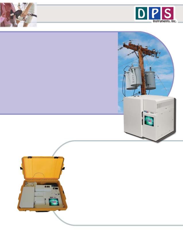
The DPS TOGA GC Systems are designed to analyze oil from
electrical insulation materials that may have decomposed under
thermal, or electrical stresses. The gaseous decomposition products
indicate the type of fault inside the transformer. The DPS TOGA GC
Systems separate all 11 components in one injection; Hydrogen,
Oxygen, Nitrogen, Methane, Carbon Monoxide, Ethane, Carbon Dioxide,
Ethylene, Propane, Acetylene, and Propylene. All compounds are
detected with the sensitive and universal Helium Ionization Detector
(HID). Our innovative 2 column and valve configuration simplifies this
analysis. The DPS TOGA GC Systems follows ASTM 3612C for gas
analysis using headspace injection. The headspace sample can be
injected using a multi-vial autosampler, or a single sample headspace
accessory can be built into our Series 600 Lab GC, or the Portable
Companion 2, allowing you to take the analyzer with you into the field.
Only a small tank of Helium is need to operate the GC System. The
fast heating and rapid cooling column oven in every DPS GC assures
rapid sample turnaround. The fully integrated TOGA GC Analyzer
Systems are small and lightweight and all DPS systems are modular
for expandability, upgrades, and easy service.
Available Configurations Include:
600-C-078 - Series 600 TOGA GC Analyzer (HID, Headspace Concentrator, 2 Columns)
500-C2-078 - Companion 2 Portable TOGA GC Analyzer (HID, Headspace Concentrator,
2 Columns)
Series 600 GC
TOGA - Gas Analysis
HID Detector
Detector Temperature = 200C
Collector = -100V
Component Area ppm High Voltage = 800V
Hydrogen 831.2 1000 Carrier = Helium @ 200 kPa
Oxygen 2722.6 1000 Column = Mol Sieve & Silica Gel in Series
Nitrogen 2147.6 1000 Temp Program = 60C (4 min) to 220 @ 10C/min
Methane 7037.0 1000
CO 3685.2 1000
Ethane 24484.2 1000
CO2 7996.0 1000
Specifications may change without notice.
Ethylene 19515.4 1000
Propane 30906.7 1000
Acetylene 18363.6 1000
Propylene 27521.3 1000
Companion 2 Portable GC
(with Headspace Concentrator)
9/2020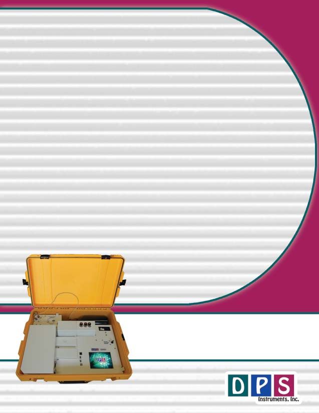
DPS Companion 2 TOGA Layout
                                 Small High Pressure Gas Cylinder
                  Valve Oven
Gas Connections                                      Power connection
                                                       with breaker
                                                       and line filter

                                                        Vial Heater
                                                        and Cover

 Rugged                                                 Detector
watertight
  case

                                On-Column Injector
    GC Oven

                        Valve Oven
                                                Headspace Vials

        2 Columns                                                   HID Switch
        inside Oven

                          USB Connections       Color Touchscreen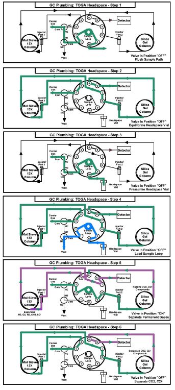
Plumbing Diagram
 TOGA Headspace Concentrator - The
    Headspace Concentrator for Companion GC’s
    are built right in to provide the shortest
    possible sample path. The Sample Vial is
    heated and then consistently Pressurized
    before loading the Sample Loop. A fixed
    Sample Loop ensures reproducible sampling
    and the sample lines are Flushed between
    analyses to limit any cross over contamination.
    The entire sequence of the Headspace
    Concentrator is automated through the
    Timeline sequence of the DPS GC Control
    Software for the analysis of one sample at a
    time, while two other samples are heated to
    equilibrate.

 TOGA Plumbing Diagram - In the 1st Step
    the carrier gas is diverted to Flush out the
    Sample Lines between runs. During the 2nd
    Step the carrier gas flows to the analytical
    column and the Headspace Vial is heated with
    the Vial Heater and allowed to equilibrate. The
    Sample Probe is then inserted into the
    Headspace Vial. During the 3rd Step the
    Headspace Vial is pressurized for a few
    seconds. In the 4th Step the sample is loaded
    onto the Sample Loop by releasing the
    pressure in the headspace vial. In the 5th Step
    the Sample Valve is rotated to the ON position
    and the carrier gas sweeps the components
    from the Sample Loop onto the analytical
    columns.

 TOGA Column Configuration - The unique 2
    column configuration simplifies the compound
    separation and analysis of the TOGA
    Headspace sample. The columns are plumbed
    in series through the same Sample Valve as
    the Headspace Concentrator.

    In Step 5 the Sample Valve is rotated to Inject
    the sample onto the analytical columns. The
    Silica Gel column retains CO2 & the C2+
    hydrocarbons, while the lighter compounds
    (H2, O2, N2, CH4, & CO) pass through and
    are further separated on the Molecular Sieve
    column. Once the lighter compounds have been
    separated the valve is rotated back in Step 6
    and the heavier compounds (CO2 & C2+
    hydrocarbons) are separated on the Silica Gel
    column.

                                                      TOGA Headspace
                                                      Plumbing Diagram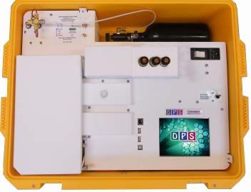
TOGA Vial Preparation Station

Clean Headspace Vials - One of the most difficult
    parts of the TOGA analyses is the sampling
    proceedure. The first step is taking a gas tight
    syringe and inserting the needle under the
    sureface of the oil to get a representative sample.
    The second step in injecting the oil into a clean vial.
    If either step is not sucessful, then you will see
    Oxygen and Nitrogen contamination from the air.

To insure that the sample vial is clean we have built in
    a Vial Preparation Station. Using the same
    technique that cylinder manufacturers employ to
    clean gas cylinders between uses; we evacuate,
    then re-fill the vial with helium several times to
    reduce Oxygen and Nitrogen to low ppm levels.
    The helium comes from the same supply as the
    carrier gas. A 2nd Method is loaded in the DPS
    Software to automatically clean the vials. The
    sample probe is inserted through the septum and
    the START button is pressed. The vials are
    prepared one at a time, but several can be
    prepared at once to be used throughout the day.

Plumbing Diagram - The first diagram is simplified
    to show that we evacuate and re-fill the vial using
    carrier gas. The 2nd diagram is the atual plumbing
    configuration when the Vial Preparation Station is
    connected to the rest of the TOGA plumbing.

                                                              TOGA Vial Preparation Diagrams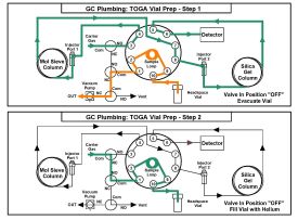
TOGA Gas Chromatograph Features

 System Configuration - A Simple and efficient configuration using two packed columns, one valve,
      and a single HID Detector. The Silica Gel column separates all of the compounds except it has trouble
      with the permanent gases. To solve this problem, we have added a Molecular Sieve column in series
      with the Silica Gel column to separate the permanent gases. Once they are separated we switch the
      valve back to take the Molecular Sieve column out of the sample path and let the remaining
      compounds travel through the Silica Gel column to the HID detector.

 Sample Information - The eleven most common compounds are included in this analysis scheme
      which meets ASTM-D3612C methodology. The compounds included in this method are H2, O2, N2,
      CH4, CO, C2H6, CO2, C2H4, C2H2, C3H6, and C3H4. The results from the analysis of these
      compounds helps target the underlying fault condition of the transformer. The action levels indicate
      the concentration levels where the falut is severe and action should be taken to mitigate any possible
      dangerous situation.

                                             Parts per Million (ppm)

No.        Compound       Detection Limit                  High Concentration                   Action Level
1          Hydrogen             50                              20,000                          100-500
2          Oxygen               10                              20,000                             NA
3          Nitrogen             10                              20,000                             NA
4          Methane              10                              20,000                          100-400
5          Carbon Monoxide      10                              20,000                          100-1000
6          Ethane               10                              20,000                          100-400
7          Carbon Dioxide       10                              20,000                          150-3000
8          Ethylene             10                              20,000                          500-2000
9          Propane              10                              20,000                          100-500
10         Acetylene            10                              20,000                          100-400
11         Proplyene            10                              20,000                          100-500

 Headspace Accessory - The built-in headspace vial accessory, including vial heater, sample valve,
      pressure and vent solenoids, and sampling probe help automate the TOGA analysis in either the
      Companion or Series 600 GC TOGA Systems. The pre-purged vial containing the oil sample is heated
      and allowed to equilibrate in the vial heater prior to analysis. There are positions for 3 vials, so once
      the first has equilibrated, the analysis can proceed one sample after another. The analysis is only
      manual as far as the user needs to insert the sample probe into the headspace vial. The remainder
      of the analysis sequence is automated.

 Headspace Autosampler - For a completely automated TOGA System the Series 600 GC can be
      equipped with a Headspace Autosampler with a 40 vial capacity. Once the vials are loaded the
      atosampler and Series 600 TOGA GC System work in unison to analyze and report the sequence of
      samples.
TOGA GC Control Software
Easy to learn and master using a
Graphical User Interface (GUI) and
Color Touch Screen.
Editors let you customize the files
associated with the GC Method. Oven Temp Program Editor
Method Name
GC Program Page
Timeline Editor
File Selection Arrows
Navigation Buttons to Quickly jump
from one screen to another.
Most pages are one button away!
Carrier Pressure 1 Editor
Keyboard Number Pad
to Enter Filenames for entering ValuesGC Status pages display the
parameters in the method, both
graphically and as text and values.
Oven Status
Method Editor
Detector Status
System Status
Run Status
System status
pages display
the health
and viability
of the GC
instrument.
Hardware Configure Names
Diagnostics Plumbing - Steps 1...6TOGA GC Specifications:
Series 600 Oven Module:
Electronics Module:
- Ambient to 400oC Column Oven
- Enter and store GC Methods via Color Touch Screen
- Actual and set-point display of all GC parameters - Up to 100 oC per/min Oven Ramp
- Safety Limits on all user entered parameters - Fast Cooldown 300 oC to 50 oC in 3.5 min
- Oven Temperature Programs (OTP) with Multiple Ramps - 1000 watt total Heater Elements
- Pressure Programs for Carrier Gases with Multiple Ramps - Temperature Ramps with 0.1 oC set-point resolution
- Timeline for sequencing Relays and Valve - 23 x 23 x 20 cm area for Glass, SS, or Capillary Columns
- Detector Control of all Parameters on one page
- Electronic Pressure Controllers (EPC’s):
Atmospheric Pressure & Temperature Compensation
Companion 2 Oven Module:
EPC Pressure Control with 0.1 kPa set-point resolution - Ambient to 325 oC Column Oven
- Plug and Play GC Control, Oven, and Detector Board - Up to 80 oC per/min Oven Ramp
- Microprocessor Controlled - Fast Cooldown 300 oC to 50 oC < 4 min
- Proprietary Digital Signal Processing - 200 watt Heater Element
- Digital Signal Outputs for each Detector - Temperature Ramps with 0.1 oC set-point resolution
- Universal voltage input (85 – 240 Vac) with line
- 12.5 x 10.5 x 12.5 cm area for Packed, or Capillary Columns
filter and breaker.
- 7 amps at 48 Vdc total power consumption
Detector: Built-In Accessories:
HID – Helium Ionization Detector (10 ppm detection limit,
- Sample Valve - Electronically Actuated
dependent on sample loop size)
- Heated Valve Oven
- Headspace Concentrator
- 400 oC Temperature Limit with 0.1 oC set-point resolution - Headspace Vial Prep Station
- 24-bit Digital Outputs for the detector via USB - Flow Control Solenoids
- EPC Pressure Control with 0.1 kPa set-point resolution
Injector:
Columns: - Heated On-column Injector
Molecular Sieve - Multiple Pressure Ramps with 0.1 kPa set-point resolution
Silica Gel
Data Communications:
Results: - Bi-directional communication with popular Data System
Automatically calibration corrected and reported in % or ppm
Network Connectivity:
- Enterprise Compatible Network GC running Windows XPe
- Ethernet Connection using Windows Network Protocol
- On Board ETX Computer for GC Control and
Data Acquisition
- Remote Control of GC and Data Acquisition
over LAN
Lab Quality Analyses in the Field,
“It Goes with you Anywhere!”You can also read