PIM Test Solutions for All Applications - COMMUNICATION Passive Intermodulation Analyzers - Rosenberger
←
→
Page content transcription
If your browser does not render page correctly, please read the page content below

Passive Intermodulation Analyzers

PIM Test Solutions for All Applications

COMMUNICATION
Rosenberger Group
Rosenberger is one of the worldwide leading suppliers of
controlled impedance and optical connectivity solutions,
system components for mobile communications networks,
data centers and test & measurement as well as high voltage
contact systems.

2
Contents

                                     Company Profile                                                     4

                                     PIM Test Solutions for all Applications                             6

                                     Definition of Intermodulation                                       7

                                     Stressed PIM Test on Site                                           9

                                     Site Testing                                                       10

                                     Testing in Production Environment                                  14

                                     Multiport Analyzer                                                 18

                                     Test Lab and Product Design Environment                            22

                                     Frequency Bands                                                    25

                                     Accessories                                                        25

                                     Service                                                            26

                                     Support and Sales Locations                                        27

Our Rosenberger online catalog
contains the current standard
product range with specific
details, including data sheets,
assembly instructions and panel
piercings.
www.rosenberger.com/ok/pim

                                  Rosenberger Hochfrequenztechnik GmbH & Co. KG | www.rosenberger.com    3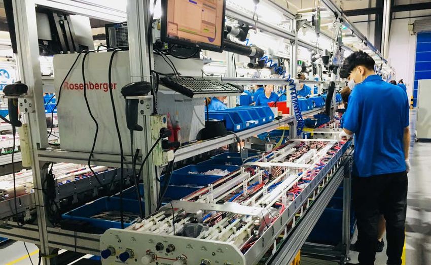
Company Profile
Competencies & Technology
Rosenberger’s mission is to be recognized as an innovation and technology leader within its
business segments. The most modern manufacturing technologies, the highest possible levels
of efficiency in production and continuous development are our core competencies guaranteeing
not only fast delivery and strict adherence to delivery dates, but also the highest levels in product
quality.

4
Company Profile
Quality and the Environment
Ensuring the optimum quality of products and services and
taking responsibility for our environment are fundamental
elements of Rosenberger's corporate philosophy.
Our approach to ensuring quality covers more than just the
optimization of parts and products – it also includes the con
tinuous improvement of all company processes: from product
development, planning, procurement, production, sales, and
logistics right through to environmental policy.
To summarize, we want to offer maximum benefits for our
customers all over the world.
We aim to act in an environmentally conscious manner, use
materials economically, protect natural resources, recycle, and
ensure energy efficiency.
As we have continuously improved our processes and con
sistently applied our quality management systems, we have
been awarded many certificates.
Certifications
■■ IATF 16949
■■ DIN EN 9100
■■ ISO 9001
■■ ISO 14001
■■ DaKKs accreditation according to DIN EN ISO 17025
Rosenberger has won a number of prestigious quality awards
and prizes from several renowned customers and organizations
for achieving its quality and environmental objectives.
Rosenberger Hochfrequenztechnik GmbH & Co. KG | www.rosenberger.com 5
PIM Test Solutions for all Applications High-speed data transmission in today’s global mobile communications networks demands high efficiency of net work infrastructure. Passive Intermodulation (PIM) in a network can cause serious interferences and significantly degrade the network quality and impact KPI figures. The cause of Passive Intermodulation is very complex and uncertain. It can be caused by low-grade transmission line components or even loose connectors, dirty surfaces, magnetic materials or the surrounding environment like a rusty roof. As a global leader of RF connectivity solutions, Rosenberger has a strong expertise in manufacturing low-PIM components as well as PIM T&M solutions for all applications: ■■ R&D / Test Lab ■■ Production Environment ■■ Site Testing Passive Intermodulation Passive Intermodulation is a non-linear response of two or more signals of different frequencies mixing together in a passive device, e.g. antenna, cable, connector or splitter. Today, PIM has become a very serious and challenging task for mobile operators, equipment vendors and component manufacturers due to frequency planning in modern communication networks, the usage of high-power transmitters and more sensitive receivers in base stations. If a PIM with sufficient magnitude generated from a transmitter falls within an adjacent receiver channel, it causes serious interferences to the base station receiver and will significantly degrade the network quality of service. The cause of PIM is very complex and uncertain. Even dirty surfaces, poor soldering, and loose connections will cause serious intermodulation. Hence, in theory, it cannot be calculated nor be simulated by software. To verify the PIM and look for the root cause, specific test instruments are required. Passive Intermodulation Analyzers Passive Intermodulation Analyzers are professional measurement instruments which are characterized by very low self intermodulation and high power level signal output. Their high accuracy receiver allows fast and precise measurements of the 3rd, 5th and 7th order intermodulation of passive devices under high- power conditions, e.g. connectors, cable assemblies, antennas, filters and other passive components. 6
PIM – Definition
Definition of Intermodulation
Passive Intermodulation
Intermodulation occurs when two or more signals mix
on a non-linear device and create undesired output at
other frequencies.
3RZHU
In a communications system, this means that signals
in one channel may cause interference with adjacent
channels.
Considering that an input signal contains two frequen
cies, intermodulation can be indicated as follows: ,0 ,0
fIM = mf1 ± nf2
f1 and f2 are carrier frequencies
fIM is the intermodulation frequency
m + n is the order of fIM. For example, when I,0 I,0 I,0 I I I,0 I,0 I,0
fIM = 2f1- f2, fIM is called the 3rd order intermodulation )UHTXHQF\
frequency. Commonly, the 3rd, 5th and 7th order inter
modulation signals will be considered. The 3rd order
intermodulation signal always represents the worst
case condition of unwanted signals generated since it
is closest to the carriers and has the highest amplitude.
G%P
Intermodulation is normally specified in terms of dBm
or dBc. For example, +43 dBm (20 Watt) is a typical in
put power level specified for device under test (DUT). If
the allowable intermodulation level for DUT is required
to be -117 dBm, thus the specification is -117-43 =
-160 dBc. I,0 I I I,0
IEC-62037 is an international standard for RF connec
tors, cable assemblies and cable intermodulation level
measurement. It defines the intermodulation level, test I,0 [II
I I
principle and test procedure. In IEC standard chap [
ter 6, it requires that the residual intermodulation of I
5[ 7[
an analyzer should be at least 10 dB below the speci
fied value of DUT. In the above example, the residual
intermodulation of the analyzer should be less than ,0
-170 dBc. The lower the self-intermodulation, the more
accurate the test results obtained. I 0+]
Rosenberger Hochfrequenztechnik GmbH & Co. KG | www.rosenberger.com 7
8
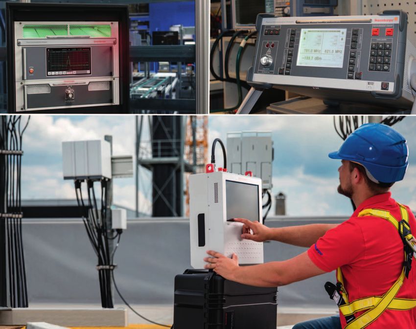
Stressed PIM Test on Site Continuous Wave (CW) PIM Site Testing A whole new approach of battery powered PIM testing delivers mobile operators unprecedented distance-to-PIM accuracy. Rosenberger’s CW PIM methodology represents the most precise approach as opposed to conventional PIM testing products based on the pulse method. Unlike pulse testing CW ensures there are no gaps with continuous power which simulates the conditions a Base Transceiver Station (BTS) experiences during actual operation. This comprehensive and highly accurate solution for PIM discovery comes at a time when testing for PIM is increas ingly critical to mobile operators and equipment manufac turers looking to maximize the performance and reliability of cellular network infrastructures. Rising competition and the imminent arrival of 5G services combined with ageing network infrastructure, cell tower co-location and higher than ever user QoS expectations, risk exposing network PIM vulnerabilities on an unprecedented scale. Operators and manufacturers are already well aware of the negative impact of PIM so we are delighted to offer a much more accurate PIM Site Analyzer, allowing them to achieve and maintain ultra-low PIM levels. While pulse- based PIM testing has been the traditional approach it is not reliable enough for comprehensive detection of all potential failures – including the quality of components and workmanship. Our own research has found that pulse test equipment has the potential of leaving many errors to go unnoticed. The system under test must be consistently loaded with sufficient power of at least 2 x 20 W to replicate the same conditions the BTS experiences when in operation. This is when component behaviour will likely change and can become unstable. The inherent design of pulse-reliant test equipment makes reaching and sustaining these power loads impossible. Rosenberger Hochfrequenztechnik GmbH & Co. KG | www.rosenberger.com 9
Site Testing
Broadband. Precise. Future-proof.

10
Site Testing The Rosenberger portable and multifunctional broadband PIM Site Analyzer provides the best alternative of per forming the most precise and efficient PIM tests on site. Rosenberger Hochfrequenztechnik GmbH & Co. KG | www.rosenberger.com 11
Site Testing
The PIM Site Analyzer consists of a single master unit with band-specific, interchangeable filter units, since the
form factor of the filter units is the same.
Take out one filter unit, e.g., 900 MHz, and replace with another filter unit, e.g., 1800 MHz, without any calibration
of the filter unit, potential adaptors, test cable, or operational mode(s). Future-proof plug and play concept cover
ing 700 to 2700 MHz.
Benefits
■■ Broadband base unit 700 to 2700 MHz with field interchangeable, band-specific filter units
■■ Stressed PIM tests – continuous wave (CW) signal simulates real operating conditions of the base station
(in conformity with IEC 62037-1)
■■ Outstanding PIM performance < -125 dBm (< -130 dBm typical)
■■ No on-site calibration
■■ Accuracy of < 0.3 m for PIM distance to fault (DTF) measurement
■■ Future-proof for upcoming bands
■■ Hardware ready for later CPRI SW upgrade
Features
■■ Optional broadband VSWR/RL module incl. DTF measurement (error correction with open/short/match)
■■ In-built WiFi for remote control via optional Android tablet
■■ Operation via batteries or external power supply
■■ VSWR/return loss measurements
■■ Antenna isolation measurement
■■ Integrated spectrum analyzer
■■ 12" touchscreen
■■ Intuitive software operation
■■ Exchangeable test port adaptors (7-16 and 4.3-10)
Wide range of tools & accessories
12Site Testing
Fast and easy interchangeable band filter units
Specification Overview
IM order 3rd, 5th, 7th, 9th, 11th, 13th, 15th, 17th
Output power at test port 23 ... 46 dBm
Residual PIM < -125 dBm (< -168 dBc @ 2 x +43 dBm) typical < -173 dBc
PIM and RL/VSWR vs. distance < 0.3 m depends on number of PIM sources and accuracy of cable velocity factor
accuracy resolution
DTF range Down to -120 dBm PIM, 0 to 150 m
Frequency range (seamless) 700 ... 2700 MHz
Filter units* Interchangeable to frequency band(s) 700, 800, 850, 900, 1400, 1800, 1900, 2100, 2300, 2600 MHz
* Other frequency bands on request
Rosenberger Hochfrequenztechnik GmbH & Co. KG | www.rosenberger.com 13Testing in Production Environment Exceptionally modular. Precise. Efficient. 14
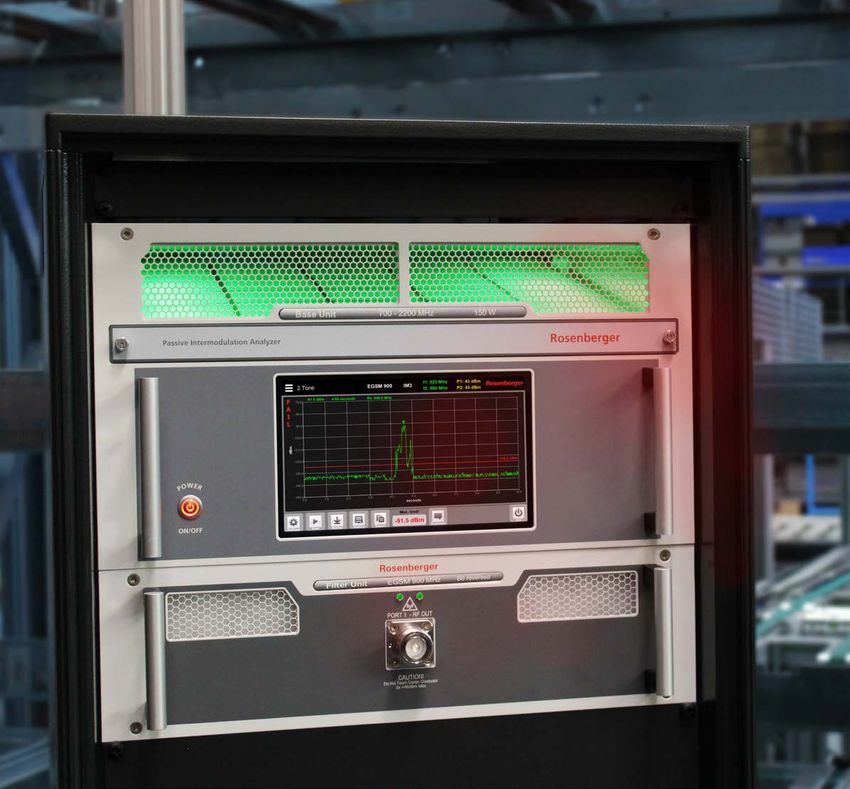
Testing in Production Environment

Basic line                      Multifunctional line

Rosenberger Rack Analyzers are designed to make PIM tests in production
or test lab environments exceptionally modular, precise, and efficient.

                       Rosenberger Hochfrequenztechnik GmbH & Co. KG | www.rosenberger.com   15
Testing in Production Environment
The budget-friendly broadband base unit concept offers maximum flexibility thanks to the option of connecting up
to 11 filter units to one base unit. Integrated DTF measurement enables faster fault-finding by accurately pointing
out the source of PIM.
With the plug-and-play filter concept, intuitive software operation, and easy-to-replace dust filters, it is possible to
create a significant reduction in production downtime caused by changes in test frequencies or maintenance and
servicing work.
Benefits
■■ Broadband base units 700 to 2200 MHz and 2100 to 2700 MHz
■■ Connect up to 6/11 filters to one base unit via optional easy-to-install switch matrix
■■ Time-efficient, automatic band switching when measurement band is changed
(thanks to the optional switch matrix)
■■ Designed for 24/7 production use
Features
■■ Intuitive, user friendly software operation
■■ Easy-to-replace dust filters to reduce downtime caused by maintenance work
■■ No production downtime when setup is rearranged (plug-and-play filter inserts)
■■ 9" touchscreen, Win7 OS
■■ Temperature controlled fan for quiet operation
■■ Optional safety port to remote disable amplifiers from test chamber contact
■■ Exchangeable test port adaptors (7-16 and 4.3-10)
Easy-to-replace dust filters
16Testing in Production Environment
Rosenberger provides 2 lines of rack models
Basic Line Multifunction Line
Application range Robust and field proven design for standard Exceptionally modular multifunction equipment,
applications easy handling and maintenance
Frequency range 300 ... 500, 600 ... 2200, 2100 ... 2700, 700 ... 2200, 2100 ... 2700 MHz
3400 ... 3600 MHz (600 ... 3500 MHz on request)
DTF – Integrated in base unit (no separate module
needed)
Dust/cleaning Part of recommended annual calibration service Easy-to-replace dust filters in base unit and filter
units
Features 2-tone, sweep 2-tone, sweep, DTF, spectrum analyzer, VSWR/
return loss, power sweep, isolation measurement,
CPRI option
Specification Overview
Basic Line Multifunction Line
IM order 3rd, 5th, 7th, 9th, 11th, 13th, 15th, 17th 3rd, 5th, 7th, 9th, 11th, 13th, 15th, 17th
Output power at test port (filter unit) 2 x 36 ... 46 dBm 2 x 23 ... 46 dBm
Residual PIM < -128 dBm (< -171 dBc @ 2 x +43 dBm) < -128 dBm (< -171 dBc @ 2 x +43 dBm)
< -131 dBm (< -174 dBc @ 2 x +43 dBm) typical < -131 dBm (< -174 dBc @ 2 x +43 dBm) typical
PIM and RL/VSWR vs. distance – < 0.3 m, all bands – depends on number of
accuracy resolution PIM sources
Range – Down to -120 dBm PIM, 0 to 150 m
Easy-to-install switch matrix
Rosenberger Hochfrequenztechnik GmbH & Co. KG | www.rosenberger.com 17Multiport Analyzer Time saving during measurement – less screwing of the cables. 18
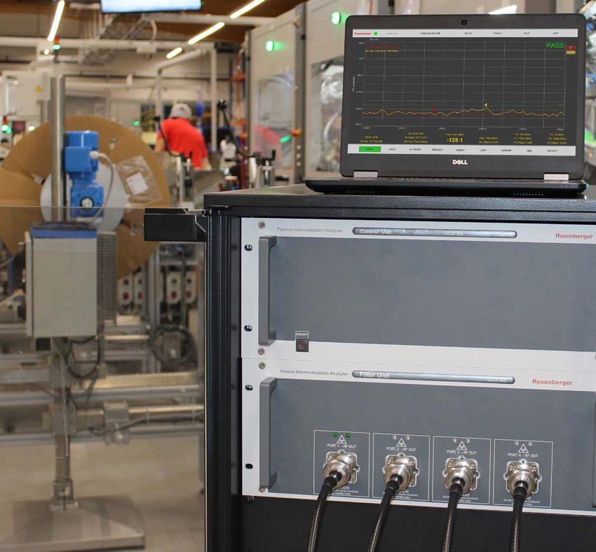
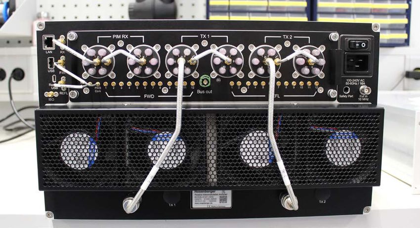
Multiport Analyzer The Multiport Analyzer can help to significantly reduce PIM test time in production lines. Due to the multiport capabili ties, up to 4 (optionally: 8) ports in same frequency can be tested sequentially. Rosenberger Hochfrequenztechnik GmbH & Co. KG | www.rosenberger.com 19
Multiport Analyzer
The Rosenberger multiport PIA (Passive Intermodulation Analyzer) provides an easy way to precisely determine
the intermodulation characteristics of
■■ Antenna
■■ Transmission line
■■ Connector
■■ Jumper
■■ Filter and combiner
■■ Splitter
■■ Other passive components
in all LTE 600, LTE 700, LTE 2600, AMPS, Dig.Div., EGSM, DCS, PCS, WiMAX and UMTS frequency range.
This Analyzer is designed for the use in production lines to measure the reversed 3rd, 5th, 7th, 9th, 11th, 15th and
17th order intermodulation products. The control unit of the Analyzer is equipped with a system controller, high-
power amplifiers and a receiver. The Analyzer is controlled by the supported remote software.
The test setup complies with the test methods suggested by proposal paper IEC 62037-1.
Specification Overview
IM order 3rd, 5th, 7th, 9th, 11th, 13th, 15th, 17th
Output power at test port (filter unit) 2 x 36 ... 46 dBm
Residual PIM < 128 dBm (< -171 dBc @ 2 x +43 dBm)
< 131 dBm (< -174 dBc @ 2 x +43 dBm) typical
Control by remote software via external PC (USB)
Exchangeable test port adaptors 7-16 and 4.3-10
20Multiport Analyzer
Setup for 8-port measurement
Rosenberger Hochfrequenztechnik GmbH & Co. KG | www.rosenberger.com 21Test Lab and Product Design Environment Portable. Flexible. Budget friendly. 22
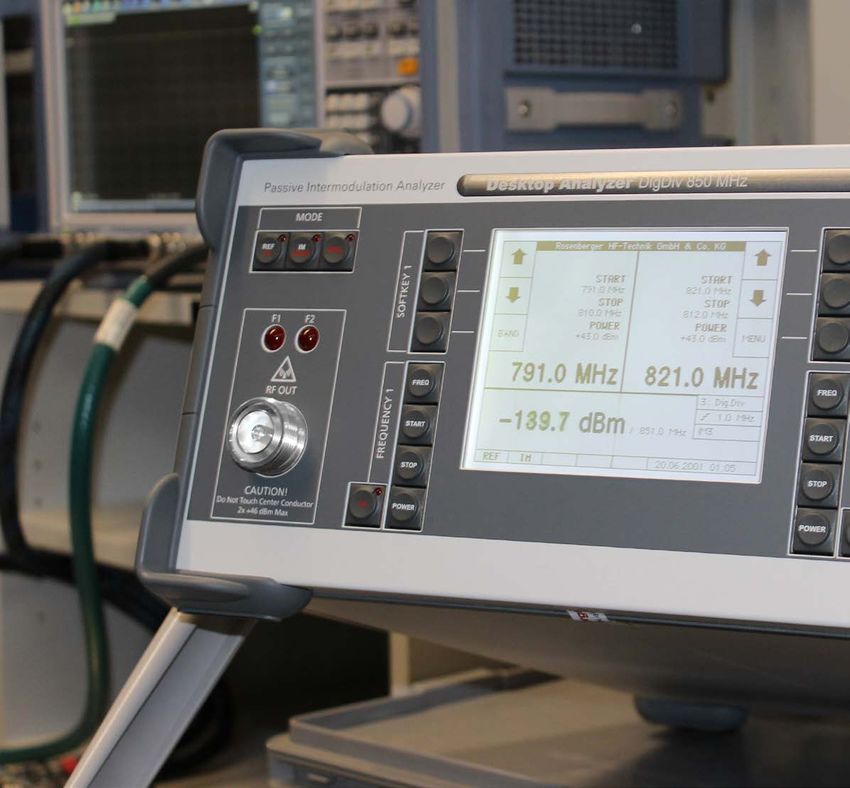
Test Lab and Product Design Environment

                                     Basic line

                Multifunction line

   Rosenberger desktop analyzers are portable and flexible
   for R&D and test labs.

Rosenberger Hochfrequenztechnik GmbH & Co. KG | www.rosenberger.com   23
Test Lab and Product Design Environment
The budget friendly broadband base unit concept offers maximum flexibility to include another extension filter to
a base unit (basic line) or add any other filter unit in the range of 700 to 2700 MHz to the base unit (multifunction
line).
It allows continuous flexibility in an ever changing environment.
Benefits
■■ Reduction of T&M investment cost (for multiband-testing)
■■ High flexibility/portability in test environment
Features
■■ Basic line: 1 additional filter unit can be added*
■■ Single band units for band specific testing
■■ Outstanding dynamic residual IM-Level < -171 dBc (2 x +43 dBm), typical -174 dBc
■■ Fast & efficient PIM testing
*698 to 1000MHz: one base model 700, 800, 850, 900 MHz can have one additional filter from any other of these frequency bands
1800 to 2100 MHz: one base model 1800, 1900, 2100MHz can have one additional filter from any other of these frequency bands
Rosenberger provides 2 lines of desktop models
Basic Line Multifunction Line
Application range Portability and flexibility in production line, Multifunction desktop base unit with plug and play
R&D and test labs exchangeable filter units supports various types
of measurements in production environment, R&D
and test labs
Frequency range 300 ... 400, 600 ... 1000, 1400 ... 1500, 700 ... 2700 MHz (600 ... 3500 MHz on request)
1800 ... 2200, 2500 ... 2700, 3400 ... 3600 MHz
DTF – Integrated in base unit (no separate module
needed)
Features 2-tone, sweep 2-tone, sweep, DTF, spectrum analyzer, VSWR/
return loss, power sweep, isolation measurement,
CPRI option, in-built WiFi for remote control via
optional Android tablet, 12" touchscreen, intuitive
software operation, exchangeable test port
adaptors (7-16 and 4.3-10)
Specification Overview
Basic Line Multifunction Line
IM order 3rd, 5th, 7th, 9th, 11th, 13th, 15th, 17th 3rd, 5th, 7th, 9th, 11th, 13th, 15th, 17th
Output power at test port 36 ... 46 dBm 23 ... 46 dBm
Residual PIM < -128 dBm (< -171 dBc @ 2 x +43 dBm) < -128 dBm (< -171 dBc @ 2 x +43 dBm)
< -131 dBm (< -174 dBc @ 2 x +43 dBm) typical < -131 dBm (< -174 dBc @ 2 x +43 dBm) typical
PIM and RL/VSWR vs. distance – < 0.3 m, all bands – depends on number of
accuracy resolution PIM sources
Range – Down to -120 dBm PIM, 0 ... 150 m
24Frequency Bands and Accessories
Frequency Bands
Band Band No. f1 (MHz)*, DL f2 (MHz)*, DL RX (MHz), UL
Tetra 390 390 … 400 390 … 400 380 … 385
Tetra 392 392 … 400 392 … 400 380 … 388
Tetra 422 422 … 430 422 … 430 410 … 418
Tetra 462 462 … 470 462 … 470 450 … 458
LTE 600 B71 617 … 652 617 … 652 663 … 698
LTE 700 for max. RX PIM 745 … 793 745 … 793 698 … 730
LTE 700LU B12, B13, B14 and B17 728 … 764 728 … 764 698 … 716/
776 … 798
APT700 B28 758 … 803 758 … 803 703 … 748
Dig.Div B20 791 … 821 791 … 821 832 … 862
AMPS B5 869 … 894 869 … 894 824 … 849
EGSM B8 925 … 960 925 … 960 880 … 915
EGSM-R 921 … 960 921 … 960 876 … 915
LTE 1400 B11 and B21 1475,9 … 1510,9 1475,9 … 1510,9 1427,9 … 1462,9
DCS B3 1805 … 1880 1805 … 1880 1710 … 1785
PCS B2 1930 … 1990 1930 … 1990 1850 … 1910
PCS and AWS B2 and B4 1930 … 2155 1930 … 2155 1710 … 1910
TD-SCDMA-A B34 2010 2017,5 2025
UMTS B1 2110 … 2170 2110 … 2170 1920 … 2060
TD-SCDMA-F B39 1900 … 1920 1900 … 1920 1880 … 1890
WCS B30 2345 … 2360 2345 … 2360 2305 … 2315
TD-SCDMA-E B40 2442 … 2484 2442 … 2484 2300 … 2340
LTE 2600 / IMTE B7 2620 … 2690 2620 … 2690 2500 … 2570
LTE 3500 B42 3510 … 3594 3510 … 3594 3410 … 3484
* Frequency range can differ between models for details see specific datasheet
Other frequencies on request
Accessories
■■ Adaptors in-series
■■ Adaptors inter-series
■■ PIM reference adaptors -110 dBm
■■ Exchangeable test port adaptors (7-16 and 4.3-10)
■■ Low-PIM terminations
■■ Test cables 7-16 / 7-16 and 4.3-10
For more information visit:
www.rosenberger.com/pia
Rosenberger Hochfrequenztechnik GmbH & Co. KG | www.rosenberger.com 25Service
Repair & Factory Calibrations
To ensure highest precision of measurements, we recommend a factory calibration interval of 12 months.
In-house calibration & repair service is optionally available. If you wish to send back a unit for factory calibration or
repair, for smooth transaction please contact us prior to shipment.
Factory Calibration FAQs
■■ Calibration: Setting and calibration of the unit to the values based on factory-provided, initial calibration. Check
for latest Firmware update
■■ Calibration frequency: To ensure highest precision of measurements we recommend a calibration interval of
12 months
■■ Cycle time: Standard cycle time is 10 working days after receipt of unit
■■ Service options: Service options such as on-site calibration service or a service contract are also available
Download Software & Tools
www.rosenberger.com/pia/downloads
Service Contact
Phone + 49 8684 18-1777
Fax + 49 8684 18-39 1777
pia_service@rosenberger.com
26Service – Support and Sales Locations
Support and Sales Locations
Europe, Middle East, Africa Americas
Rosenberger Hochfrequenztechnik GmbH & Co. KG Rosenberger Site Solutions, LLC
Hauptstraße 1 P.O. Box 8817, Lake Charles, LA 70606, USA
83413 Fridolfing, GERMANY Phone + 1 337 598 5250
Phone + 49 8684 18-0 Fax + 1 337 598 5290
Fax + 49 8684 18-1499 rlss@rlss.us
info@rosenberger.com www.rlss.us
www.rosenberger.com
Brazil
Rosenberger Domex Telecom
Rosenberger Site Solutions GmbH
Cabletech Avenue, 601
Mayerhofen 45A
Guaramirim
83410 Laufen, GERMANY
CEP 12295-230
Phone + 49 8684 18-5000
Cacapava - Sao Paulo, BRAZIL
Fax + 49 8684 18-1499
Phone + 55 - 12 - 3221 8500
siso@rosenberger.com
Fax + 55 - 12 - 3221 8543
www.rosenberger.com/siso
vendas@rosenbergerdomex.com.br
www.rosenberger.com
Asia Pacific
Rosenberger Asia Pacific Electronic Co., Ltd.
No. 3, Anxiang Road, Block B
Tianzhu Airport Industrial Zone
Beijing, 101300, PR CHINA
Phone + 86 10 80 48 1995
Fax + 86 10 80 48 2438
info@rosenberger.com.cn
www.rosenberger.com
India
Rosenberger Electronic Co. (India) Pvt Limited
Plot No. 263, Sector 6
IMT Manesar, Gurgaon
Haryana-122050, INDIA
Phone + 91 1244 77 55 00
Fax + 91 1244 77 55 01
info@rosenberger.in
www.rosenberger.com
Status January 2019 – Technical modifications and errors excepted. Similar images.
Rosenberger Hochfrequenztechnik GmbH & Co. KG | www.rosenberger.com 27Microsite
For more information refer to our microsite:
www.rosenberger.com/pia
Rosenberger Hochfrequenztechnik GmbH & Co. KG
Hauptstraße 1 | 83413 Fridolfing
P.O. Box 1260 | 84526 Tittmoning
Germany
Phone +49 8684 18-0
info@rosenberger.com
www.rosenberger.com
Certified by IATF 16949 · DIN EN 9100 · ISO 9001 · ISO 14001
Order No.
pA 199320 · Info580PIACatEN
2000/2019
Rosenberger® is a registered trademark of Rosenberger Hochfrequenztechnik GmbH & Co. KG.
All rights reserved.
© Rosenberger 2019You can also read