OPTIMAL 350 I. MANUAL - Optimal Tree Spade
←
→
Page content transcription
If your browser does not render page correctly, please read the page content below

OPTIMAL 350

I.    MANUAL

Manufacturer:                     Distributor:

Optimal-Vertrieb Opitz GmbH       Prichard's Nursery Equipment LLC
Eysoelden M 41                    P.O.Box 549
91177 Thalmaessing                Portland, TN 37148
Germany                           U.S.A.

Phone: ++ 49 - 9173 - 79 18 0     Phone:   (423) 326 - 0753
Fax:    ++ 49 - 9173 - 79 18 49   Fax:      (615) 323 - 7667
eMail: info@opitz-optimal.com     eMail:   sales@optimaltreespades.com
web:    www.opitz-optimal.com     web:     www.optimaltreespades.com
-2-

                                CONTENTS

                                           page

     Safety Warnings                        3

1.   Operating Specifications               5

2.   Assembly                               7

3.   Putting into Service                   8

4.   Operating Instructions                 9

5.   Care and Maintenance                   12

6.   Attachment Points                      13

7.   Electrical connection diagram          14
-3-

         WARNING           Operator must have read and understood instructions
                           before running the tree spade.
                           Untrained operators can cause injury or death.

         Safety Alert Symbol:                This symbol is used for important safety messages.
                                             When you see this symbol, follow the message to
                                             avoid personal injury or death.

Never use tree spade without instructions. See machine signs (decals), and Operation & Maintenance Manual of tree
spade. The operation instructions for power unit must be followed.

Before starting operations, bolts and hydraulic fittings must be checked to make sure they are free of damage and well
tightened. Defective or loose hose pipes might cause serious injuries and therefore must be replaced immediately.

The operator is responsible for ensuring that no person is near the tree spade when in operation.

No one should be underneath the raised tree spade or near shearing and pinching areas, or near any hydraulic
components. We are advising the user that due to their functional positions and movements the danger areas cannot be
furnished with protective guards.

Keep bystanders well away from work area.

Do not perform any manual work on the tree or shrub when it is inside the tree spade. In particular, do not check the
position of the tree or shrub by hand or feet when it is inside the tree spade. Do not tie the tree or shrub when it is near
or inside the machine.

When sight is limited, an assistant should direct the operator by hand signals.

When driving, the tree spade should be in the lowest possible position.
When moving and working on public roads, the traffic rules and regulations must be adhered to.

Never leave power unit with engine running or with lift arms up.

To park, engage parking brake and put tree spade flat on the ground.

When doing cleaning, maintenance or repair work, lower the tree spade to the ground
and stop the engine of the power unit.

Never modify equipment. Use only original spare parts approved by manufacturer for this particular model tree spade.

When digging, it might happen that a stone gets caught between two blades and the blades get bent. This causes
tremendous tension in the steel blade. Do not try to release the stone by means of a crow bar or other tools. Place the
digging head again into the planting hole and retract the blades. Thereby the stone will come loose and the blades which
got a high degree of bending strength will regain their former shape. After that the root ball can be dug again.

The operator must be sure that the ground he is going to dig is free from any underground installations such as cables,
pipes or any other utilities or dangerous matter. Damaging such underground installations or matter is dangerous and
might result in serious injury or death.

Safety stickers have been placed on the tree spade to warn the user of possible dangers. In case a safety sticker has
been worn or destroyed, it must be replaced immediately.
Safety stickers can be ordered with your distributor or the manufacturer.
-4-

-5-

1.       Operating Specifications

Description                         Tree Spade OPTIMAL 350

Serial Number                       350

Capacity                            upper root ball diameter              36 cm
                                    root ball depth                       30 cm

dimesions of                        height                                78 cm
basic machine                       width, gate closed                    69 cm
                                    width, gate open                      99 cm
                                    clearance between open gate           48 cm

weight                              basic machine, empty                  150 kg

rated type of attachment            attachment by means of back plate to skid steer loader or
                                    excavator

                                    the power unit must be equipped with an
                                    auxiliary double-acting hydraulic circuit for implements:
                                            working pressure:    140 – 160 bar
                                            oil flow:             25 l/min.

controls                            electro-hydraulic valves, rotary control switch

field of application                tree nurseries, gardens
-6-
2. Assembly
IMPORTANT: When doing assembly work, heed relevant
instructions of manufacturers of power unit!
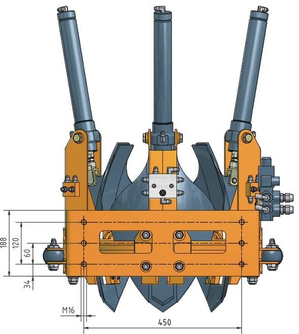
2.1. Back plate
The tree spade is attached to the power unit by means of a back plate.
The back plate is procured from the manufacturer of the power unit,
or it might be fabricated according to the drawings and instructions of
the manufacturer of the power unit.
The back plate is to be furnished with borings ø18 as per drawing page 12.
At these attachment points the tree spade is bolted tightly to the back plate.
2.2 Installation of Electro-Hydraulic Control
The item numbers in the brackets refer to below diagram.
2.2.1 Install rotary switch (item 1) at suitable and dry location in the power unit, e.g. on the
instrument panel.
2.2.2 Connect two-pole cable (item 4) to the power supply of the power unit (12 V).
( The brown wire is negative, the blue wire is positive).
2.2.3 Install three-pole female plug (item 3) next to the quick-connect of the hydraulic supply.
Now the tree spade and the power unit are ready for operation.
Power unit-7-
3. Putting into Service
The tree spade with the back plate is attached and secured to the power unit.
Both the hydraulic connecting hoses of the tree spade are to be connected
to the hydraulic disconnect of the auxiliary hydraulic circuit of the power unit.
The plug of the electric control cable is to be plugged into the socket on
the power unit
IMPORTANT: The hydraulic disconnect of the tree spade and
the power unit must match and must be connected
properly. Faulty connections are extremely dangerous.
When operating the power unit, follow the
instructions of the operating manual of the
power unit !-8-
4. Operating Instructions
IMPORTANT: The Operator must be a reliable person. Before commencing
production work, he or she must study these operating instructions
thoroughly.
The following safety instructions must be observed:
It is the operator's prime duty to ensure that any persons must stay clear
off the danger area. Special care must be taken that no one is ever
under the raised tree spade, or near the potential shearing and pinching
areas, or near the opened gate, near the spades or near any hydraulic
components.
Do not perform any manual work at the tree or shrub when it is inside the
tree spade. In particular, do not check the position of the tree or shrub by
hand or feet when it is inside the tree spade. Do not bind the tree or
shrub when it is near or inside the machine.
When sight is limited, an assistant should direct the operator by hand
signals.
Before starting to work with the tree spade, make sure the hydraulic
fittings and the bolts are properly tightened and are free from any
defects.
4.1 The Controls
The electro-hydraulic controls are to be operated as follows:
Rotary Switch Work Movement
function 1 : blades / gate lock open / close
function 2 : frame open / close
The function required is preset with the rotary switch and then
activated by the manual control valve of the auxiliary hydraulic circuit
of the power unit.-9-
4.2 Operation
First lower the tree spade by means of the lift arms of the power unit the blade points are
about 20 cm (8”) above the ground.
Preset function 1 “blade / gate lock” with rotary switch, and activate “open” with manual
control.
Then preset function 2 “gate” and activate “open” with manual control. Now the gate opens.
Drive the tree spade with gate opened towards the tree. When the tree is positioned in the
centre of the main frame, preset function 2 “gate” and activate “close”.
With the gate closed, lower the tree spade to the ground and bring it in a horizontal
position. Check again if tree is positioned in the centre of the frame and correct, if
necessary.
When the gate is properly closed, preset 1 “blade / gate lock” and activate “close”. Make
sure the gate is now properly locked.
Locking the gate before starting the digging operation is of utmost
importance and must never be omitted !
If the gate is not locked properly, the frame may be bent !
If the loader is equipped with rear stabilizers, extend rear stabilizers with the appropriate
control valve of the loader.
Preset function 1 "blades / gate lock" and actuate "close" with manual valve. Now the
blade cylinders force the blades into the soil.
When the tree spade begins to lift in the process of digging, retract the blades and then
continue digging. Never tilt the tree spade forward and backward with the tilting cylinder of
the power unit.
Once all spades have been completely pressed into the soil, the tree spade with the
planting material inside is lifted out of the ground by means of the lift arms of the power
unit.
When operation of the tree spade is finished, put rotary switch into idle position by setting
item 1 at rotary switch.- 10 -
IMPORTANT: When moving and working on public roads, the traffic rules
and regulations must be adhered to.
When driving, the tree spade should be in the lowest possible position.
When digging, it might happen that a stone gets caught between two
blades and the blades get bent. This causes tremendous tension in the
steel blade. Do not try to release the stone by means of a crow bar or
other tools.
Place the digging head again into the planting hole and retract the
blades. Thereby the stone will come loose and the blades which got a
high degree of bending strength will regain their former shape. After that
the root ball can be dug again.
4.3 Releasing the Tree
When transplanting or root-balling, lower the tree spade by means of the lift arm, retract
blades and unlock gate (preset function 1 “blades / gate lock”, manual control “open”).
Finally open the gate (preset function 2 “gate”, manual control “open”) and reverse the
loader.- 11 -
5. Care and Maintenance
5.1 Blade Guides
The blades are furnished with plastic linings which slide on steel guides.
Once the plastic lining is worn to the point that the heads of the countersunk screws are
flush with the surface of the plastic linings, they must be replaced to prevent the screws
from damaging the guides.
IMPORTANT:Keep the guides clean.
5.2 No Lubrication
All sliding surfaces and bearings are made of plastic and do not require any lubrication.
5.3 Hydraulic Oil Supply
Check level of hydraulic oil regularly. For checking, retract all blades "up"
and lower the tree spade to the ground. If in that position the oil level is
below the mark of the sight glass, oil must be refilled.
5.4 Hydraulic Hoses
All hydraulic hoses must be inspected at least once per year. Damaged hoses
must be replaced. All hoses must be replaced latest 6 years they have been initially
installed..
5.5 Hydraulic Cylinders
When the tree spade is not used for more than 2 weeks, all piston rods of the hydraulic
cylinders must be cleaned and then sprayed with a preserving oil.
IMPORTANT: Tree spade must be lowered to the ground and switched
off when doing cleaning, maintenance or repair work !
Use original spare parts only !
The tree Spade must be inspected by an expert on
operational safety once per year !
Do not alter the design of the tree spade without having
consulted the manufacturer !- 12 - 6. Attachment Points
- 13 -

7.   Electrical connection diagram
OPTIMAL 350

II.   ERSATZTEILLISTE
      SPARE PARTS LIST
      LISTE DES PIÈCES DE RECHANGE
      350013-

Hersteller – Manufacturer - Fabricant:

Optimal-Vertrieb Opitz GmbH
Eysölden M 41
91177 Thalmässing
GERMANY

Phone:          ++49 (0) 9173 – 79 18 - 0
Fax.:           ++49 (0) 9173 – 79 18 - 49
e-mail:         info@opitz-optimal.com
web:            www.opitz-optimal.com
Tafel - Table - Feuille 1
OPTIMAL 350
ERSATZTEILLISTE - SPARE PARTS LIST - PIÈCES DE RECHANGE
Grundmaschine / Basic Machine / cadre de base
Pos. Menge Bezeichnung ET-Nummer
Item Quantity Description Part Number
Pos. Quantité Description Numéro de commande
1 1 Grundmaschine 350 2000350011
main frame
cadre de base
2 3 Spatenzylinder 350 3010100070
spade cylinder 350
vérin de bêche
3 6 Schwenkbolzen 3070350020
adjustment pin
arbre à rotule
4 6 Lagerbuchse GSM-1618-15 544161815
bush GSM-1618-15
douille
5 3 Mutter M14 DIN 936 502140936
nut M14 DIN 936
écrou M 14 DIN 936
6 3 Federklappbolzen 14 x 28 5071428
locking pin
goupille à ressort
7 3 Gabelkopf DIN 71752, G 14 x 28 5074140
fork joint
tête fourche
8 3 Kunststoffleiste 3060350010
plastic guide
patin en plastique
9 18 Schraube M 6 x 25 DIN 7991 501060257991
countersunk socket screw M 6 x 25
vis M 6 x 25 DIN 7991Tafel - Table - Feuille 1
OPTIMAL 350
ERSATZTEILLISTE - SPARE PARTS LIST - PIÈCES DE RECHANGE
Grundmaschine / Basic Machine / cadre de base
Pos. Menge Bezeichnung ET-Nummer
Item Quantity Description Part Number
Pos. Quantité Description Numéro de commande
10 6 Schraube M 6 x 16 DIN 7991 501060167991
countersunk socket screw M 6 x 16
vis M 6 x 16 DIN 7991
11 20 Sicherungsmutter M 6 502060985
nut M 6 DIN 985
écrou de serrage
12 3 Spaten kpl. 3160350050
spade complete
bêche complète
13 3 Einspannbuchse 14 x 20 x 13, 506142013
tapered bush
entretoise
14 3 Spatenführung außen, rechts 3060350020
guide RH, outside
guide de bêche extérieur, droit
15 3 Spatenführung außen, links 3060350030
guide LH, outside
guide de bêche extérieur, gauche
16 12 Einstellschraube M22x1,5 3140350010
adjustment screw
vis de réglage
17 12 Schraube M 12 x 70 DIN 7991 50112070912
countersunk socket screw M 12 x 70
vis M 12 x 70
18 1 Verriegelungszyl. 350, HZ25/1 3010300090
gate lock cylinder
vérin de verrouillage
19 1 Schraube M 5 x 10, vz. DIN 914 50105010914
screw M 5 x 10 DIN 914
vis M 5 x 10 DIN 914Tafel - Table - Feuille 1
OPTIMAL 350
ERSATZTEILLISTE - SPARE PARTS LIST - PIÈCES DE RECHANGE
Grundmaschine / Basic Machine / cadre de base
Pos. Menge Bezeichnung ET-Nummer
Item Quantity Description Part Number
Pos. Quantité Description Numéro de commande
20 3 Mutter M12 DIN 934 502120934
nut M 12 DIN 934
ècrou M 12 DIN 934
21 3 Schraube M 12 x 30 DIN 933 50112030933
hex head screw M 12 x 30
vis M 12 x 30 DIN 933
22 2 Scharnierbolzen ø25 3070350050
hinge pin
axe de charnière
23 4 Lagerbuchse GSM-2023-30 544202330
bush GSM-2023-30
douille
24 2 Scheibe DIN 125, 21 mm 506920
washer 21 mm
rondelle
25 2 Sicherungsmutter M 20 x 1,5 DIN 985 50220150985
nut M 20 x 1,5 DIN 985
écrou de serrage
26 2 Spannhülse 8 x 36, DIN 1481 506798351481
spring-type straight pin 8 x 36 DIN 1481
douille de serrage
27 2 Öffnungszylinder 3010200041
gate cylinder
vérin d'ouverture
28 4 Ansatzschraube M16/ø20f7 3140650010
shoulder bolt M 16
contre ècrou
29 4 Sicherungsmutter M 16 DIN 985 502160985
nut M 16 DIN 985
écrou de serrageTafel - Table - Feuille 1
OPTIMAL 350
ERSATZTEILLISTE - SPARE PARTS LIST - PIÈCES DE RECHANGE
Grundmaschine / Basic Machine / cadre de base
Pos. Menge Bezeichnung ET-Nummer
Item Quantity Description Part Number
Pos. Quantité Description Numéro de commande
30 1 Umschaltventil 547045
valve
valve
31 2 Schraube M 6 x 50 DIN 912 50106050912
socket head screw M 6 x 50
vis M 6 x 50 DIN 912
32 1 Ölverteiler 3050350010
oil manifold
distributeur d'huile
33 2 Schraube M 6 x 70 DIN 912 50106070912
socket head screw M 6 x 70
vis M 6 x 70 DIN 912
34/ 1 Ventilschraube M 8 mit Mutter 515179842
35 setting screw with sealing nut
vis de valve avec écrou
36 2 Verschraubung 515WE8LNPT
union
boulonnerie
37 10 Verschraubung 515GE6LR
union
boulonnerie
38 2 Verschraubung 515WE6LR
union
boulonnerie
39 4 Verschraubung 515GE6LR1/4K
union
boulonnerie
40 12 Verschraubung 515GE6LR1/8K
union
boulonnerieTafel - Table - Feuille 1
OPTIMAL 350
ERSATZTEILLISTE - SPARE PARTS LIST - PIÈCES DE RECHANGE
Grundmaschine / Basic Machine / cadre de base
Pos. Menge Bezeichnung ET-Nummer
Item Quantity Description Part Number
Pos. Quantité Description Numéro de commande
41 6 Verschraubung 515WE6LR
union
boulonnerie
42 4 Lagerbuchse GSM-2528-30 544252830
bush GSM-2528-30
douille
43 1 Halter f. Steuerventil 3150350030
bracket for valve
Maintien pour valve
44 2 Schraube M 6 x 20 DIN 933 50106020933
hex head screw M 6 x 20
vis M 6 x 20 DIN 933
45 2 Scheibe DIN 125, 6 mm 506906
washer
rondelle
46 4 Sicherungsmutter M 6 502060985
nut M 6 DIN 985
écrou de serrageTafel - Table - Feuille 2
OPTIMAL 350
ERSATZTEILLISTE - SPARE PARTS LIST - PIÈCES DE RECHANGE
Spatenzylinder / spade cylinder / vérin de bêche
Pos. Menge Bezeichnung ET-Nummer
Item Quantity Description Part Number
Pos. Quantité Description Numéro de commande
1 1 Zylinderrohr, geschw. 40/25 3020400080
cylinder body
corps de vérin
2 1 Kolbenstange ø 25 x 445 3030250060
piston rod
Tige de piston
3 1 Kolben 40 25 230 3124025230
piston
piston
4 1 Mutter M 16 x 1,5 DIN 936 50216150936
nut M 16 x 1,5 DIN 936
ècrou M 16 x 1,5 DIN 936
5 1 Führungsbuchse, HZ 40/25 3114025020
guide bush HZ 40/25
douille de guidage HZ 40/25
6 1 Mutter M 14 DIN 936 502140936
nut M 14 DIN 936
ècrou M 14 DIN 936
7 1 Gabelkopf DIN 71752, G 14 x 28 re., vz. 5074140
fork joint
tête fourche
8 1 Federklappbolzen 14 x 28 5071428
locking pin
goupille à ressort
9 1 Abstreifer P7 - 25 (W4-25) 5160325
scraper
racloir
10 1 Stangendichtung S 8 - 25 (blau!) 5160225
piston rod seal
joint de tige de pistonTafel - Table - Feuille 2
OPTIMAL 350
ERSATZTEILLISTE - SPARE PARTS LIST - PIÈCES DE RECHANGE
Spatenzylinder / spade cylinder / vérin de bêche
Pos. Menge Bezeichnung ET-Nummer
Item Quantity Description Part Number
Pos. Quantité Description Numéro de commande
11 1 O-Ring 45 x 3 517045030
o-ring
o-ring
12 1 O-Ring 25 x 2,5 5170250025
o-ring
o-ring
13 1 Kolbendichtsatz OMK40 5160140
piston seal
joint de piston
14 2 Verschraubung 515WE6LR
union
boulonnerie
Dichtsatz 516004025603
seal kit
jeu de jointsTafel - Table - Feuille 3
OPTIMAL 350
ERSATZTEILLISTE - SPARE PARTS LIST - PIÈCES DE RECHANGE
Öffnungszylinder / gate cylinder / vérin d’ouverture
Pos. Menge Bezeichnung ET-Nummer
Item Quantity Description Part Number
Pos. Quantité Description Numéro de commande
1 1 Zylinderrohr 3020320020
cylinder body
corps de vérin
2 1 Kolbenstange ø 20 x 171, geschw. 3030200020
piston rod
tige de piston
3 1 Kolben, HZ 32/20 3123220010
piston
piston
4 1 Mutter M 14 x 1,5 DIN 936 50214150936
nut M 14 x 1,5 DIN 936
ècrou M 14 x 1,5 DIN 936
5 1 Distanzbuchse 3110350010
spacer
boulon d'entretoisement
6 1 Führungsbüchse, HZ 32/20 3113220010
guide bush
boite de guidage
7 2 Lagerbuchse GSM-2023-30 544202330
bush GSM-2023-30
coussinet-2023-30
8 1 Abstreifer 5160320
scraper
racloir
9 1 Stangendichtung 5160220
piston rod seal
joint de tige de piston
10 1 O-Ring 28 x 2.5 5170280025
o-ring 28 x 2,5
o-ring 28 x 2,5
11 1 O-Ring 16 x 2 5170160020
o-ring 16 x 2Tafel - Table - Feuille 3
OPTIMAL 350
ERSATZTEILLISTE - SPARE PARTS LIST - PIÈCES DE RECHANGE
Öffnungszylinder / gate cylinder / vérin d’ouverture
Pos. Menge Bezeichnung ET-Nummer
Item Quantity Description Part Number
Pos. Quantité Description Numéro de commande
12 1 Kolbendichtsatz 2x24 5160132
piston seal
joint de piston
13 2 Verschraubung 515GE6LR1/4K
union
boulonnerie
Dichtsatz 516003220601
seal kit
jeu de jointsTafel - Table - Feuille 4
OPTIMAL 350
ERSATZTEILLISTE - SPARE PARTS LIST - PIÈCES DE RECHANGE
Verriegelungszylinder / gate lock cylinder / vérin de verrouillage
Pos. Menge Bezeichnung ET-Nummer
Item Quantity Description Part Number
Pos. Quantité Description Numéro de commande
1 1 Zylinderrohr 3020250020
cylinder body
corps de vérin
2 1 Kolbenstange 3030160020
piston rod
tige de piston
3 1 Kolben 2516225 3122516225
piston
piston
4 1 Sicherungsmutter M 10 DIN 985 502100985
nut M 10 DIN 985
écrou de serrage
5 1 Verschraubung VSTI 515VSTI1
union
boulonnerie
6 1 Abstreifer 5160316
scraper
racloir
7 1 Stangendichtung RS 16/20,6 51602016206
piston rod seal
joint de tige de piston
8 1 O-Ring 12,3 x 2,4 5170123024
o-ring
o-ring
9 1 Kolbendichtung 5160125
piston seal
tige de piston
10 2 Verschraubung 515GE6LR1/8K
union
boulonnerie
Dichtsatz 516002516611
seal kitTafel - Table - Feuille 5
OPTIMAL 350
ERSATZTEILLISTE - SPARE PARTS LIST - PIÈCES DE RECHANGE
Hydrauliksystem - hydraulic system - Système hydraulique
Pos. Menge Bezeichnung ET-Nummer
Item Quantity Description Part Number
Pos. Quantité Description Numéro de commande
1 1 Umschaltventil 547045
valve
valve
2 2 Verschraubung gerade 3/8 515GE6LR3/8
union 3/8
Raccord fileté droit 3/8
3 2 Verschraubung gerade 3/8 515GE12LR
union 3/8
Raccord fileté droit 3/8
4 2 Verschluss 515BUZ12L
plug
Bouchon
5 2 Verschraubung gerade 3/8 515GE8LR3/8
union 3/8
Raccord fileté droit 3/8
6 1 Halter f. Steuerventil 3150350030
bracket for valve
Maintien pour valve
7 2 Schraube M 6 x 20 50106020933
hex head screw M 6 x 20
vis M 6 x 20
8 2 Scheibe 6 DIN 125 506906
washer 6 DIN 125
rondelle 6 DIN 125
9 4 Sicherungsmutter M 6 502060985
lock nut M 6
écrou de sécurité M 6
10 2 Schraube M 6 x 50 50106050912
socket head screw M 6 x 50
vis M 6 x 50
11 1 Ölverteiler 3050350010
oil manifoldTafel - Table - Feuille 5
OPTIMAL 350
ERSATZTEILLISTE - SPARE PARTS LIST - PIÈCES DE RECHANGE
Hydrauliksystem - hydraulic system - Système hydraulique
Pos. Menge Bezeichnung ET-Nummer
Item Quantity Description Part Number
Pos. Quantité Description Numéro de commande
12 2 Schraube M 6 x 70 50106070912
socket head screw M 6 x 70
vis M 6 x 70
13 1 Drosselschraube 515179842
oil flow adjuster
vis de réglage
14 10 Verschraubung gerade 1/8 515GE6LR
union 1/8
Raccord fileté droit 1/8
15 2 Winkelverschraubung 1/4 515WE8LNPT
ellbow union 1/4
coude fileté 1/4
16 2 Winkelverschraubung 1/8 515WE6LR
ellbow union 1/8
coude fileté 1/8
17 1 Hydraulikschlauch NW6 513061028513
hydraulic hose
Tuyau hydraulique
18 1 Hydraulikschlauch NW6 513061030013
hydraulic hose
Tuyau hydraulique
19 1 Hydraulikschlauch NW6 513061037013
hydraulic hose
Tuyau hydraulique
20 1 Hydraulikschlauch NW6 513061037013
hydraulic hose
Tuyau hydraulique
21 4 Verschraubung 515GE6LR1/4K
union
boulonnerie
22 12 Verschraubung 515GE6LR1/8K
unionTafel - Table - Feuille 5
OPTIMAL 350
ERSATZTEILLISTE - SPARE PARTS LIST - PIÈCES DE RECHANGE
Hydrauliksystem - hydraulic system - Système hydraulique
Pos. Menge Bezeichnung ET-Nummer
Item Quantity Description Part Number
Pos. Quantité Description Numéro de commande
23 2 Hydraulikschlauch NW6 513061039012
hydraulic hose
Tuyau hydraulique
24 2 Hydraulikschlauch NW6 513061043012
hydraulic hose
Tuyau hydraulique
25 2 Hydraulikschlauch NW6 513061059012
hydraulic hose
Tuyau hydraulique
26 2 Hydraulikschlauch NW6 513061063012
hydraulic hose
Tuyau hydraulique
27 6 Winkelverschraubung 1/8 515WE6LR
ellbow union 1/8
coude fileté 1/8
28 2 Hydraulikschlauch NW6 513061044011
hydraulic hose
Tuyau hydraulique
29 3 Hydraulikschlauch NW6 513061053013
hydraulic hose
Tuyau hydraulique
30 1 Hydraulikschlauch NW6 513061042011
hydraulic hose
Tuyau hydraulique
31 2 Hydraulikschlauch NW6 513061043012
hydraulic hose
Tuyau hydraulique
32 3 Spatenzylinder 350 3010100070
spade cylinder 350
vérin de bêcheTafel - Table - Feuille 5
OPTIMAL 350
ERSATZTEILLISTE - SPARE PARTS LIST - PIÈCES DE RECHANGE
Hydrauliksystem - hydraulic system - Système hydraulique
Pos. Menge Bezeichnung ET-Nummer
Item Quantity Description Part Number
Pos. Quantité Description Numéro de commande
33 1 Verriegelungszyl. 350, HZ25/1 3010300090
gate lock cylinder
vérin de verrouillage
34 2 Öffnungszylinder 3010200041
gate cylinder
vérin d'ouvertureTafel - Table - Feuille 6
OPTIMAL 350
ERSATZTEILLISTE - SPARE PARTS LIST - PIÈCES DE RECHANGE
Steuerteil – control box – boîtier de contrôle
Pos. Menge Bezeichnung ET-Nummer
Item Quantity Description Part Number
Pos. Quantité Description Numéro de commande
1 1 Drehschalter 1,2 5470A220-521
rotary switch 1,2
commutateur rotatif
2 1 Steckdose 3-polig 5998JB001943
3-pole socket
Fiche 3 pôles
3 2 Kabelverschraubung M20x1,5 5121100000
straight cable fitting
boulon de câble
4 1 Kabel 2x1,5 – 150cm (59”) 5122015
cable 2x1,5 – 150cm (59”)
Câble 2x1,5 – 150cm (59”)
5 1 Kabel 2x1,5 – 550cm (216“) 5122015
cable 2x1,5 – 550cm (216“)
Câble 2x1,5 – 550cm (216”)
6 1 Stecker 3-polig 5998JA001919
3-pole plug
Prise 3 pôles
7 1 Kabel 2x1,5 – 200cm (79”) 5122015
cable 2x1,5 – 200cm (79”)
Câble 2x1,5 – 200cm (79”)
8 1 Standard – Stecker 54743650
standard plug
Prise standard
9 1 2-fach Schaltteil, kpl. 201330004
10 1 Elektroteil, kpl. 2014035010LIMITED WARRANTY
Optimal-Vertrieb Opitz GmbH ("Opitz") warrants that this product will be free from defects in material and
workmanship for a period of 6 months from the date of purchase (the "Warranty Period"). If, during the
Warranty Period, this product proves to be defective, Opitz will remedy the defect by either repairing or
replacing the product or any of its defective parts, at Opitz’s option.
If you need warranty service, you must, prior to the lapse of the Warranty Period, file a claim, together with
proof of purchase and your original Warranty Certificate received at the purchase of the product, with
Prichard´s Nursery Equipment, LLC; P.O. Box 250; Harrison, TN 37341-0250; USA. After a warranty claim
is properly filed, Opitz or its designated representative will evaluate the warranty claim. This warranty is
conditioned upon your reasonable cooperation with Opitz in the evaluation of your warranty claim and the
implementation of any remedy. When supplying replacement product or parts under this warranty, Opitz
reserves the right to substitute product or parts of comparable value and design for any discontinued
designs. This warranty is not transferable and applies only to the original consumer purchaser.
Opitz does not assume any responsibility for failures, breakage or causes which result from abuse, misuse,
negligence, faulty operation, unauthorized repair or alteration, accident, fire, winds, floods, moisture, other
unfavorable atmospheric conditions or other causes beyond Opitz’s reasonable control or from failure to
operate or maintain the product in accordance with the Opitz Operation Manual (a copy of which is provided
to you with the product) or from normal wear and tear under normal usage. OPITZ EXCLUDES AND WILL
NOT PAY ANY INCIDENTAL AND CONSEQUENTIAL DAMAGES ARISING OUT OF THE PURCHASE
OR USE OF THE PRODUCT. By this Opitz means any loss, expense or damage other than to the product
itself that may result from a defect in the product. Some states do not allow the exclusion or limitation of
incidental or consequential damages, so the above limitation or exclusion may not apply to you.
THE DURATION OF ANY IMPLIED WARRANTIES ARE LIMITED TO THE DURATION OF THE
COVERAGE PROVIDED BY THIS LIMITED WARRANTY AS INDICATED ABOVE; PROVIDED,
HOWEVER, THAT NOTHING IN THIS LIMITED WARRANTY SHALL GIVE YOU ANY IMPLIED
WARRANTIES YOU WOULD NOT OTHERWISE HAVE, EXTEND THE SAME BEYOND THEIR
CUSTOMARY DURATION, OR MAKE OPITZ LIABLE FOR ANY IMPLIED WARRANTIES THAT IT
WOULD NOT BE LIABLE FOR IF THIS LIMITED WARRANTY HAD NOT BEEN GIVEN. Some states do
not allow limitations on how long an implied warranty lasts, so the above limitation may not apply to you.
This warranty shall apply only to product that is purchased and used within the United States. This warranty
gives you specific legal rights, and you may also have other rights that vary from state to state.
Date of Sale: ………………………………… Product Sold: ……………………………………………
Product Serial Number: ……………………. Expiration Date of the Warranty: ………………………
Name and Address of Buyer: ………………………………………………
………………………………………………
………………………………………………
………………………………………………
Signature of Buyer: ……………………………………………….You can also read