PRACTICAL SOLUTIONS FOR RAY TRACING CONTENT COMPATIBILITY IN UNREAL ENGINE 4
←
→
Page content transcription
If your browser does not render page correctly, please read the page content below
CHAPTER 50

PRACTICAL SOLUTIONS FOR RAY
TRACING CONTENT COMPATIBILITY
IN UNREAL ENGINE 4
Evan Hart
NVIDIA

            ABSTRACT
            Though modern graphics hardware offers features and performance for
            real-time ray tracing, consumer applications like games must target legacy
            hardware to serve a large install base. This chapter addresses some
            challenges and solutions for working with ray tracing in this legacy content. In
            particular, it demonstrates a solution for mixing raster and ray traced
            translucency, as well as a set of solutions for animated foliage.

                 Figure 50-1. A forest scene rendered with ray tracing in Unreal Engine 4 (UE4) using animated
                 foliage. The scene uses ray tracing for shadows and reflections. The scene was authored by
                 Richard Cowgill using the Forest - Environment Set by Nature Manufacture available through the
                 UE4 Marketplace [4].

© NVIDIA 2021
A. Marrs, P. Shirley, I. Wald (eds.), Ray Tracing Gems II, https://doi.org/10.1007/978-1-4842-7185-8_50      845
RAY TRACING GEMS II

50.1       INTRODUCTION
           Ray tracing opens up an impressive array of graphical effects that were
           previously challenging or impractical for real-time applications such as
           games. However, all consumer-focused applications like games have a heavy
           burden of legacy support. The effects and art must be authored to work well
           on the platforms that represent the vast majority of the install base when they
           release. This constraint demands that the primary focus of the development
           effort be on content tuned to work well for rasterization. These current
           market needs to prioritize rasterization during development limit the cycles
           available to tune specifically for ray tracing.

           Due to the practical limitations of revising many man-years of asset
           development, the current path to enabling ray tracing effects in real-time
           games is to adapt the ray tracing effects to the raster-centric content already
           required. This chapter presents techniques for resolving challenges in two
           common rendering regimes: translucency and foliage. These techniques
           have been successfully used to enable ray tracing effects in shipping games.

           Though the algorithms here were implemented in the context of the Unreal
           Engine, they are broadly applicable. NVIDIA’s custom NvRTX branch of Unreal
           Engine 4 (available to anyone registered for Unreal Engine access through
           GitHub at https://github.com/NvRTX/UnrealEngine) demonstrates the
           implementation of these techniques and several more.

50.2       HYBRID TRANSLUCENCY
           Translucency in games typically means anything that is not opaque. For
           rasterization, this implies alpha blending over other geometry. This category
           covers common objects like glass and water, but it also includes particle
           effects such as smoke and fire. Importantly, translucent objects bring special
           shading and composition challenges to raster graphics due to their many
           overlapping surfaces.

50.2.1     MOTIVATION

           The standard implementation of ray traced translucency in Unreal Engine 4
           (UE4) handles all translucent effects in a single pass. Primary rays are traced
           from the viewer to just in front of the closest opaque surface. The depth buffer
           provides this max ray distance. Rays shade the closest hit, including a
           reflection bounce and any necessary shadow rays, then fire a continuation ray.

846
CHAPTER 50. PRACTICAL SOLUTIONS FOR RAY TRACING CONTENT COMPATIBILITY IN UNREAL ENGINE 4

   (a) Ray traced translucency                    (b) Rasterized translucency

   Figure 50-2. Ray traced translucency offers an impressive upgrade in shading. However, artists
   typically author the content with rasterization in mind. This scene is a variant of the Amazon
   Lumberyard Bistro [1].

Depending on the settings and material type, the continuation ray potentially
refracts. With the right settings and content, this algorithm produces a
high-quality result. Translucent interactions are perfectly sorted, shading is
substantially improved over shading used for raster translucency
(Figure 50-2), and refraction effects are supported natively. Importantly,
achieving this result requires that the content be configured appropriately.
Without proper tuning, performance challenges and graphical artifacts
commonly occur.

The most direct performance challenge with fully ray traced translucency
comes from particle effects authored for rasterization. Particle systems often
create volumetric effects with several sprites overlapping a single pixel.
Capturing each layer with full ray traced translucency requires tracing an
additional ray and one additional shading invocation. Though this may
produce high-quality volumetric effects, the performance scales quite
differently than originally intended by the artist. For example, even eight
layers of ray tracing interactions are too few to render a simple fire and
smoke particle system without clear hole artifacts where the rays terminate
too early. More importantly, ray tracing a particle system at that level of
overlap costs roughly 10 times the cost of rasterizing it. Although particle
systems are the most common example to encounter this performance
concern, the performance challenges are not limited to them alone. Artists
may place dozens of small glasses inside a restaurant that they never
intended to have a dramatic impact on the scene visuals. Due to the
order-dependent nature of compositing, one cannot mix and match the

                                                                                               847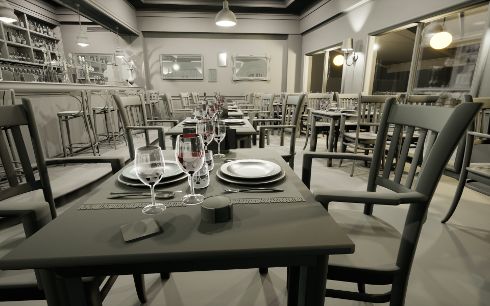
RAY TRACING GEMS II

           methods of rendering translucency. As fully ray traced translucency is an
           all-or-nothing affair, the only choices are to pay that cost for everything or to
           forgo the enhancements entirely.

           Quality challenges with fully ray traced translucency are more varied than
           those of performance issues. Particles again show up at the top of the list of
           concerns. In UE4, first among the particle challenges is that much legacy
           content relies on a particle system referred to as Cascade, as opposed to a
           newer system named Niagara. The older Cascade system completely lacks
           ray tracing support, so enabling full ray traced translucency causes all
           particles from Cascade to completely disappear. This forces a developer using
           the legacy particle system to choose between re-authoring those systems or
           foregoing ray traced translucency. Even when all particle systems are
           supported, the authoring process of treating them as screen-aligned
           billboards may or may not hold up well under the different rendering
           methodology.

           The next challenge for fully ray traced translucency comes from refraction
           and distortion. Raster translucency generally only offers distortion as a
           special effect carefully placed in the scene. Ray traced translucency
           accomplishes this distortion naturally through refraction. This requires that
           either refraction is disabled or all materials are configured properly with their
           index of refraction. The result is a choice between no distortion/refraction or
           editing potentially hundreds of materials as well as geometry to ensure that
           refraction properties have all been properly configured. Misconfigured
           refraction parameters are quite common in content that has been developed
           without the intention of supporting ray tracing from the start. A simple
           example is that of a window. Games will generally use a two-sided
           quadrilateral for the window. Even if the index of refraction is correct to drive
           the physically based rendering used by the engine, the lack of a second
           quadrilateral representing the backside of the glass will result in distortion.
           The ray will continue in the refracted direction as if looking into a solid block
           of glass. Finally, the best performance-tuning parameter for fully ray traced
           translucency presents its own image artifact challenges. Ray traced
           translucency requires that users place a limit on the number of layers traced.
           Though this greatly helps performance in cases of high depth complexity, the
           translucent surfaces beyond the limit are simply not rendered. Although the
           front one or two layers will have the most important impact on the image,
           having objects completely disappear is unfortunate (Figure 50-3).

848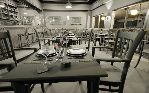
CHAPTER 50. PRACTICAL SOLUTIONS FOR RAY TRACING CONTENT COMPATIBILITY IN UNREAL ENGINE 4

            (a) Multi-layer ray traced translucency           (b) Single-layer ray traced translucency

            Figure 50-3. With only a single layer of translucency, overlapping glasses result in the glasses
            farther from the viewer disappearing in the overlapping sections.

50.2.2   OUR HYBRID APPROACH

         The hybrid translucency solution described here bridges the gap between ray
         traced translucency and raster translucency. Effects best suited for
         rasterization can use rasterization, while ray traced shading is applied to
         more important surfaces like window panes. Hybrid translucency fixes the
         ordering problem described previously by having the ray tracing pass place its
         results in an offscreen cache. The cache captures the radiance for translucent
         layers independently, rather than compositing them. This allows the
         rasterization phase of translucency to look up the shading result in the cache
         and substitute it for the shading value produced via rasterization. Importantly,
         all translucent primitives that wish to receive ray tracing effects are rendered
         twice (once via ray tracing and once via rasterization). As rasterization is used
         to composite everything, hybrid translucency is unable to provide the
         order-independent translucency benefit of fully ray traced translucency.
         However, hybrid translucency is intended to work with legacy content, which
         has already had to deal with this challenge. Further, hybrid translucency uses
         the same refraction and distortion methods as rasterization. Although those
         effects will not look any better than they did under rasterization, they will now
         function identically without the need for an artist to tune the effect specially
         for ray tracing. The result is a technique that functions and performs in a
         manner consistent with the rasterization systems for which the content has
         already been tuned, while offering greatly improved shading on surfaces like
         windows at little cost to the asset pipeline (Figure 50-4).

         Hybrid translucency’s ray traced shading cache functions by storing samples
         in a screen-space texture array. Each pixel in the framebuffer contains up to

                                                                                                               849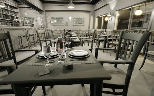
RAY TRACING GEMS II

               (a) Fully ray traced translucency               (b) Hybrid translucency with two layers

               Figure 50-4. Hybrid translucency replicates the most important visual enhancements of full ray
               tracing while continuing to support rasterized elements.

           N layers of shaded translucent surfaces (or events). Each event stores the
           reflected irradiance as well as the distance from the viewpoint. Importantly, it
           does not composite any transmission through the surface. The transmission
           is applied by the blending operations during compositing. Creating the cache
           is accomplished by a simple modification to the standard algorithm for
           handling ray traced transparency. Each pixel traces a ray from the eye into the
           scene with the maximum distance limited by the opaque geometry already
           written to the framebuffer. The closest hit is shaded and written to the first
           layer of the cache, then the ray is stepped forward and traced again to record
           additional events if necessary. The pseudocode in Listing 50-1 demonstrates
           the basic algorithm for the ray generation shader.

           Once the shading cache is created, the ray traced results must be composited
           into the scene with the raster transparency. Compositing is performed in the
           standard rasterization order. The shader for translucent materials is
           enhanced with code to check the shading cache. The check first examines
           layer 0 to see if any ray traced data was written for the pixel. If so, it compares
           the distance from the viewpoint against what was stored in the cache. If the
           distance matches within a threshold, the shading data from the cache is used.
           To prevent paying the cost of searching with every translucent pixel, objects
           not supporting ray tracing skip the search by using a uniform branch.
           Listing 50-2 contains code for applying the data from the cache.

           Importantly, the compositing pass for hybrid translucency maintains the
           shading functionality that would have otherwise applied. This allows for the
           production of reasonable results, no matter how many layers of translucency

850
CHAPTER 50. PRACTICAL SOLUTIONS FOR RAY TRACING CONTENT COMPATIBILITY IN UNREAL ENGINE 4

 Listing 50-1. Ray generation pseudocode.

 1   GBufferData OpaqueData = ReadGBufferForPixel ();
 2
 3   FarPosition = ReconstructionPosition (OpaqueData);
 4
 5   RayDescription Ray;
 6   Ray.Origin = ViewerPosition;
 7   Ray.Direction = normalize(FarPosition - ViewerPosition);
 8   Ray.MinT = 0.0;
 9   Ray.MaxT = length(FarPosition - ViewerPosition) - Epsilon;
10
11   for(int Event = 0; Event < MaxEvents; Event ++)
12   {
13       Payload HitData = Trace(Ray);
14       if(! HitData.IsHit)
15       {
16            Break;
17       }
18       else
19       {
20            Color = ShadeHit(HitData);
21            Distance = HitData.Distance;
22            RecordLayer(Event , Color , Distance);
23       }
24
25       // Step forward for next search.
26       Ray.MinT += HitData.Distance + Epsilon;
27   }

 Listing 50-2. Translucent cache search pseudocode.

 1   Color = ComputeShadingForTranslucentPixel ();
 2
 3   if (SupportRayTracing )
 4   {
 5       // Check if any layers were captured.
 6       if (Layers[pixel ][0]. Distance > 0)
 7       {
 8           Distance = Length(WorldPosition - ViewPosition);
 9
10           for(Layer = 0 : NumLayers - 1)
11           {
12               LayerDist = Layers[Pixel ][ Layer ]. Distance;
13               Delta = abs(Distance - LayerDistance);
14
15               if (Delta/Distance < Threshold)
16               {
17                   // Surface matches the cached data.
18                   Color = Layers[pixel ][ Layer ]. Color;
19                   break; // Exit the loop.
20               }
21           }
22       }
23   }

                                                                                     851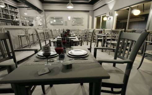
RAY TRACING GEMS II

               (a) Two-layer hybrid translucency                (b) Single-layer hybrid translucency

               Figure 50-5. Hybrid translucency gracefully falls back to the raster effect, on which the content
               already needs to rely for most systems.

           are present. The top N layers will receive ray traced shading, while the deeper
           layers will simply fall back to the effect as it would have been with
           rasterization (Figure 50-5). As the topmost layer will provide the most
           significant contribution to the image, ray tracing only a single layer of
           translucency is typically enough.

50.2.3     RELATIONSHIP TO ORDER-INDEPENDENT TRANSPARENCY

           The hybrid translucency approach described in this chapter explicitly avoids
           solving the problem of the order of translucent surfaces, but it does share
           some similarities. Depth peeling [3] converts translucency into layers to allow
           compositing in depth order, and A-buffers [2] produce sorted per-pixel lists of
           transparent surfaces. These concepts relate to the ordered sample cache
           used by this hybrid translucency algorithm. In contrast to these
           order-independent transparency (OIT) algorithms, the structure only serves
           to ensure that the closest events were captured and to optimize cache
           lookups. Importantly, this hybrid algorithm does not preclude the use of OIT
           approaches during the compositing pass. It relies on whichever one is in use
           for compositing standard raster transparency, with the key requirement that a
           single method be used to order both the raster and the ray traced
           components.

50.2.4     PERFORMANCE

           As with all advanced visual effects, managing and scaling performance is
           important with hybrid translucency. As discussed previously, hybrid
           translucency can cut the amount of shading both by reducing the objects
           considered for translucent ray tracing and by restricting the number of layers

852
CHAPTER 50. PRACTICAL SOLUTIONS FOR RAY TRACING CONTENT COMPATIBILITY IN UNREAL ENGINE 4

   (a) Ray traced translucency with two refraction events: (b) Half-resolution hybrid translucency with only the
   16.2 ms                                                 top layer traced: 4 ms + 1.5 ms

   Figure 50-6. Hybrid translucency produces overall better image quality at one third of the cost in
   this scene. Notice that much of the glassware is not completely visible in the purely ray traced
   version due to exhausting its refraction event count. All timings were taken on an RTX 3090 at
   1920 × 1080

captured. The ability to degrade more gracefully is the soul of the hybrid
translucency’s performance advantage over standard ray traced translucency.
The tracing pass for hybrid translucency is effectively identical in cost when
comparing equal numbers of events shaded. Shading two layers of refraction
rays in a complex test scene shows a cost of 16.1 milliseconds (ms) for pure
ray tracing and 16.2 ms for hybrid ray tracing (Figure 50-6a). The hybrid
method also requires an additional 1.5 ms to rasterize the translucency. (All
tests performed at 1920 × 1080 resolution on an RTX 3090.) However, the ray
traced scene suffers from translucent objects disappearing even with two
layers of events. The hybrid scene has no objects disappearing, and it can
reduce the cost to a single layer with hardly any visual impact, reducing its
cost to 7.9 ms. Additionally, the shading cache layers of hybrid translucency
can be rendered at half the resolution in a checkerboard or interleaved style
while upsampling at compositing time. As expected, halving the number of
samples halves the cost of ray tracing, reducing the cost to 4 ms for this test
case (Figure 50-6b).

Finally, all ray traced translucency can benefit from using rasterization to
compute a mask of potentially transparent pixels on the screen. Rasterizing
the few translucent objects that participate in ray tracing against the depth
buffer very quickly marks which pixels can ever produce a translucency hit.
This allows the ray generation shader to terminate without firing a ray for
regions with no coverage. For most scenes, this saves hundreds of thousands
of rays cast for what is often under one tenth of a millisecond in cost.
However, the benefit depends on the amount of translucency in the scene, so
the utility of this technique will vary.

                                                                                                               853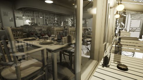
RAY TRACING GEMS II

50.3       FOLIAGE
           Foliage is an integral part of outdoor environments in nearly all games. The
           term foliage in the context of games covers everything from large trees to
           grass. In UE4, as in most games, the majority of foliage is handled through
           somewhat specialized systems to allow the high density typically desired.
           This system replicates dozens to hundreds of identical copies, commonly
           called instances, of the meshes with different transformations to produce a
           rich environment. On top of the varied static transforms, foliage systems
           typically utilize some form of vertex shader animation. Though it may be as
           simple as a sine wave to sway the grass back and forth, this ambient motion
           brings life to a scene.

50.3.1     REPRESENTING ANIMATED FOLIAGE

           Data management is the key issue with supporting foliage in a ray tracing
           context for games. Exploiting the instanced nature of foliage is the first step
           in managing the costs. Placing foliage as instances into the top-level
           acceleration structure (TLAS) with shared entries in the shader binding table
           provides the solution to manage the costs associated with thousands of
           objects. A modest forest scene in UE4 spends over 6 ms of CPU time setting
           up ray tracing instances that are setup independently, as opposed to 0.6 ms
           for using shared setup. Importantly, it may even be worthwhile to forego
           multiple levels of detail, as the costs associated with managing the multiple
           levels of detail may outweigh the gains. One aspect to managing the instances
           is efficiently culling to ensure that only the relevant instances are processed.
           In general, ray tracing makes the culling problem more difficult, as reflection
           rays are harder to account for. A good solution is to cull by projecting the
           bounding sphere to a solid angle from the viewpoint. A culling angle of
           1–2 degrees ensures that the screen area impacted by the object is respected
           across all but the most extreme regimes. Tall trees will accurately cast their
           long shadows and be prominent in reflections, while the impact of the
           thousands of small tufts of grass will be minimized.

           The ambient motion of foliage substantially magnifies the data management
           issue while also introducing costs of its own. Bottom-level acceleration
           structures (BLASs) must be created uniquely for each different deformation.
           This means that the simple vertex shaders used to add ambient motion to all
           the foliage in a scene are producing thousands of unique meshes each from
           the perspective of ray tracing. The naive solution requires running a compute

854
CHAPTER 50. PRACTICAL SOLUTIONS FOR RAY TRACING CONTENT COMPATIBILITY IN UNREAL ENGINE 4
shader over each instance to update the vertices, then refitting or rebuilding
the BLAS each frame. A test of a simple forest scene in UE4 shows that even
capping this processing at 256 instances per type costs over 50 ms of GPU
processing on an NVIDIA RTX 3090. Such a solution is untenable in a
real-time application. A more practical fallback is to simply skip the ambient
motion and leave all instances in their neutral poses. Placing just the static
objects instanced into the TLAS produces a very reasonable representation for
many gaming scenarios. It ensures that the foliage is accurately represented
in size and approximate location. Importantly, the ray tracing representation
is only observed as part of secondary effects. Reflections will show correctly
placed and lit foliage. Without close inspection, the lack of motion will
frequently be missed, as large near-perfect mirror reflections are
uncommon. Though occlusion effects like shadows and ambient occlusion
may often get by with a lack of motion especially when casting on moving
objects, the degree to which it is acceptable will vary based on the content.
The appearance of stationary leaf shadows on static objects will sometimes
stand out as objectionable, especially when the shadows created via shadow
maps move. Importantly, fully accurate motion, which would require the
50 ms cost mentioned previously, is not typically necessary. As long as
shadows have motion generally consistent with the behavior of the foliage as
seen by the viewer, a convincing effect is possible.
Reusing animations across multiple instances allows the shadows to have
behavior consistent with the motion prescribed for the foliage, while not
paying the cost for matching the animations exactly. Sharing the animations
between instances is a simple extension to the simulations used for
stand-alone deformed meshes. The only additional effort required is that the
result must keep the same neutral coordinate frame as the original mesh.
The translations, rotations, and scales for the instances still apply to produce
a convincing animated instance in the world. Minimizing the number of
simulated instances is important, as each additional simulated instance is
work and limits reuse. Often, convincing results are achievable with only a
single simulated instance for each distinct foliage mesh in a forest. Again, the
user never views the ray traced results directly.
50.3.2 INEXACT OCCLUSION
Though purely static foliage or replicated animations do a reasonably good job
on reflections and shadow casting from foliage onto other objects,
self-occlusion effects of foliage require a bit more care. Because the vertex
855RAY TRACING GEMS II
(a) Raster and ray tracing geometry out of sync while (b) Raster and ray tracing geometry out of sync while
using an exact shadow test using an inexact shadow test
Figure 50-7. The exact shadow test shows substantial hard shadow artifacts where the geometry
used to cast shadow rays does not match the geometry used to test the shadow rays. Applying a
stochastic bias to only the pixels known to have this challenge hides the artifact while preserving
the overall appearance.
shader animation fails to exactly match the animation used by the foliage
instances in the bounding volume hierarchy (BVH), incorrect self-occlusion is
likely to occur. This is easiest to observe with unanimated foliage in the BVH
testing against animated foliage in the raster scene. The result is streaky
shadows that slice through the foliage as it moves in and out of intersecting
with the static representation (Figure 50-7a).
Like most of the other challenges with foliage, a good solution involves
leaning into the approximations already occurring. Foliage rendering uses
several billboards and leaf cards to represent the volume of leaves on a
typical plant. Because the space being rendered can be thought of as a
volume, the occlusion testing can be as well. Statistical sampling can
approximate shadow results within the volume (Figure 50-7b). This sampling
can be accomplished by applying random offsets to the minimum hit distance
(TMin) for the shadow rays (Figure 50-8). The result is as if a cloud of samples
was evaluated above the foliage in the direction of the light source. Clearly,
the randomization will result in a noisy shadow result. However, the shadows
already rely on denoising and temporal antialiasing passes to produce soft
antialiased results. Importantly, placing the bias on TMin rather than on the
origin for the shadow ray increases the reported distance for the rays that still
856CHAPTER 50. PRACTICAL SOLUTIONS FOR RAY TRACING CONTENT COMPATIBILITY IN UNREAL ENGINE 4
(a) Mismatched geometry (b) Inexact shadow rays
Figure 50-8. The purple and blue surfaces are logically the same, but different ray traced (purple)
and raster (blue) representations. Due to the mismatch, the blue surface is in shadow with rays
traced directly from the surface. Applying a stochastic offset to the rays allows several samples to
avoid the self-occlusion.
return a shadow result. This aides the denoising process, as the sharpness of
denoising is tied to the reported hit distance. See Listing 50-3 for the setup of
this inexact shadow test.
Listing 50-3. Inexact shadow ray setup.
1 RayDesc Ray = GenerateOcclusionRay (
2 LightParameters ,
3 WorldPosition , WorldNormal ,
4 RandSample);
5
6 // Apply standard bias to avoid depth fighting artifacts.
7 ApplyCameraRelativeDepthBias (Ray , PixelCoord , DeviceZ , WorldNormal ,
NormalBias);
8
9 // If using inexact occlusion tests , apply bias to TMin.
10 if ( NeedsInexactOcclusion ())
11 {
12 Ray.TMin += GetRandomOffset () * MaxBiasForInexactGeometry ;
13 }
Finally, the inexact shadow testing is only desirable on objects and materials
that require the inexact test. Two different solutions have been deployed to
solve this. First, as foliage is the primary use case, attributes from the
G-buffer such as the shading model are useful to identify geometry wishing to
receive the effect. Simply applying it to the TWO_SIDED_FOLIAGE shading
model in UE4 will cover the most common cases. The downside is that
objects like tree branches will not participate. A more exact solution comes
from marking the target geometry explicitly. This can be done by an extra bit
in the G-buffer when there is room. For the more general case, simply
857RAY TRACING GEMS II
running an extra stencil-only pass offers a good solution. Because the
geometry already exists in the depth buffer, the pass can skip running a pixel
shader to produce alpha blending and can rely on setting the depth function to
equal for handling pixels cut out by alpha testing.
50.4 SUMMARY
The hybrid translucency and the foliage techniques described in this chapter
are insufficient on their own to handle all challenges when adding ray tracing
to content authored for rasterization. However, they stand as part of the
toolbox of methods to accomplish the task, and when combined with other
tools in an engine like UE4, impressive results are possible.
REFERENCES
[1] Amazon Lumberyard. Amazon Lumberyard Bistro. Open Research Content Archive
(ORCA), http://developer.nvidia.com/orca/amazon-lumberyard-bistro, 2017.
[2] Carpenter, L. The A-buffer, an antialiased hidden surface method. ACM SIGGRAPH
Computer Graphics, 18(3):103–108, 1984. DOI: 10.1145/800031.808585.
[3] Everitt, C. Interactive order-independent transparency. http://developer.download.
nvidia.com/assets/gamedev/docs/OrderIndependentTransparency.pdf, 2001.
[4] Nature Manufacture. Forest - environment set. Unreal Engine Marketplace,
https://www.unrealengine.com/marketplace/en-US/product/forest-environment-set,
2019.
Open Access This chapter is licensed under the terms of the Creative Commons
Attribution-NonCommercial-NoDerivatives 4.0 International License
(http://creativecommons.org/licenses/by-nc-nd/4.0/), which permits any
noncommercial use, sharing, distribution and reproduction in any medium or format, as long as you give
appropriate credit to the original author(s) and the source, provide a link to the Creative Commons license
and indicate if you modified the licensed material. You do not have permission under this license to share
adapted material derived from this chapter or parts of it.
The images or other third party material in this chapter are included in the chapter’s Creative Commons
license, unless indicated otherwise in a credit line to the material. If material is not included in the chapter’s
Creative Commons license and your intended use is not permitted by statutory regulation or exceeds the
permitted use, you will need to obtain permission directly from the copyright holder.
858You can also read