Preparing the SVT for Operations in 2021 - Tim Nelson - HPS Collaboration Meeting JLab - November 20, 2020 - Indico
←
→
Page content transcription
If your browser does not render page correctly, please read the page content below
Preparing the SVT for
Operations in 2021
Tim Nelson -
HPS Collaboration Meeting
JLab - November 20, 2020
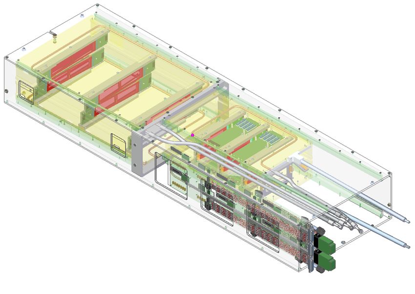
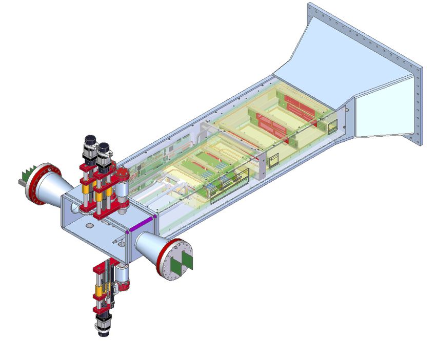
+
 e
The HPS SVT SVT, target e
 movers

7 double-layers of silicon strips, each plane measures position
(~6-10 m) and time (~2 ns) with ~0.2% – 0.35% X0/hit.
Operates in an extreme environment:
• beam vacuum and 1.5 Tesla magnetic field
 target
 constrains materials and techniques data
• sensor edges 0.5 mm from electron beam in L1 flange
 power
 must be movable, serviceable
 flange
• sensors see large dose of scattered electrons e
 must be actively cooled to -20 ˚C
• 24528 channels can output >100 gb/sec
 requires fast electronics to process data

 L4-6 (stationary)
 L1-3
 support channel
 w/ motion lever L1-3 (movable)

 DAQ
 outer box front-end 2

 w/ support ring boards
Changes for 2019: addition of new L1 and replacement of L2

 3
Changes for 2019: addition of new L1 and replacement of L2

 3
HPS SVT DAQ
 SLAC GEN3 RCE Platform

 • Developed by SLAC under gen
 program (Huffer, Haller, Herbst

• Hybrids hosting • Core software and firmwa
 experiment specific softw

 5 CMS APV25 each
 • Strong internal support fo
 well as assistance with cu
 • COB (Cluster On Board)
 • Carries 1 DTM (Data Tran
 • Single RCE for swit
 timing distribution

• In-vacuum ADC, voltage • Carries 4 DPM (Data pro
 daughter boards

 Hybrid Front End Board
 10Gbps Fulcrum • Each DPM support

 generation and power
 DPM
 (2 x RCE) Ethernet (Reconfigurable Clu
 Ethernet

 RCE Platform
 DPM Switch 10Gbps
 ATCA • RCE is Xilinx Z

 distribution/control on (40) (10, 4 Hybrids each)
 (2 x RCE)
 IPMB Back with embedde
 DPM
 RTM Plane • Provides data
 (2 x RCE)
 DTM

 Front End Boards DPM
 Clock & and software
 (1 x RCE) Trigger
 (2 x RCE) • High rate DAQ

 ADC Sample DataClock / Trigger
 Data towards > 100

 APV25 Amp ADC • Supports RTE

 RX Framing Reduction Buffer
• Penetration for digital signals
 via high-density PCB through
 Timing & Event
 flange. Optical conversion on Clocking & Control
 Trigger Building
 outside of flange.

 High density vacuum
• Firmware support for APV25 penetration for 200 Gbps ECal ROC
 burst trigger mode (50 kHz TDAQ Application
 trigger rate for 6 samples) Flange Board (4, 3 FEBs ea.)

• Wiener MPOD power supplies

 Inside Outside
 (digital) (digital⟺optical) 4
Outline of SVT Maintenance and Repair

Repair and/or replacement of radiation damaged FEBs
 • Investigation and diagnosis of damage
 • Design improvements and repair or replacement
Replacement of damaged modules, now three types:
 • L1, L2: serious damage, sensor quality issues leave only one spare
 • L3, L4: not much damage and have spares (built in 2011 for test run!)
 • L5-L7: some wirebond damage in L7. With few spares and no easy path
 to more, may have to live with some (few %) dead channels in L7.
Maintenance of SVT Infrastructure
 • SVT chiller problems and cooling system integrity
 • DAQ updates (see Sergey’s talk)
 • Odd jobs
Status and plans for work at SLAC and JLab in the COVID era
 5
FEB Damage During 2019 Operations

FEB degradation manifests as drooping 5V / 500 mA
regulator designed to supply ~300 mA total:

• 24 preamps for APV before ADCs (~10 mA each)

• bias voltage for 12 regulators that supply voltages
 to the hybrids (~5 mA each)

No current monitoring, so mechanism has been unclear,
but lowering temperatures improved overhead.

Damage meant loss of data from L7T, one of four hybrids
in L5B for most of the run.

Once recognized, we improved monitoring and were more
careful with the beam to limit further damage.

See Marcelo Vicente’s talk next!
 6
FEB Damage During 2019 Operations

FEB degradation manifests as drooping 5V / 500 mA
regulator designed to supply ~300 mA total:

• 24 preamps for APV before ADCs (~10 mA each)

• bias voltage for 12 regulators that supply voltages
 to the hybrids (~5 mA each)

No current monitoring, so mechanism has been unclear,
but lowering temperatures improved overhead.
 FEBs
Damage meant loss of data from L7T, one of four hybrids
in L5B for most of the run.

Once recognized, we improved monitoring and were more
careful with the beam to limit further damage.

See Marcelo Vicente’s talk next!
 collimator 6
FEB Damage During 2019 Operations

FEB degradation manifests as drooping 5V / 500 mA
regulator designed to supply ~300 mA total:

• 24 preamps for APV before ADCs (~10 mA each)

• bias voltage for 12 regulators that supply voltages
 to the hybrids (~5 mA each)

No current monitoring, so mechanism has been unclear,
but lowering temperatures improved overhead.
 FEBs
Damage meant loss of data from L7T, one of four hybrids
in L5B for most of the run. beampipe
 & flange
Once recognized, we improved monitoring and were more
careful with the beam to limit further damage.

See Marcelo Vicente’s talk next!
 collimator 6
FEBs: Repair or Replace?

Current Status of FEBs
• 15 built, 10 needed. After replacements during 2019 installation,
 no perfect spares left.
• 3 show symptoms of damage in 5V supply
• 1 has some kind of damage to V125 control for one hybrid, set by
 AD5144 digital potentiometer (50 in the system). Possibly a fluke,
 but are discussing how to study this.

There are many issues with the repair scenario:
 Glass transient Dielectric Main
 Type Description
 temp. Tg constant Dk suppliers
• Not clear how to accommodate component changes (e.g. larger FR stands for Fire Retardant. FR4 is a Shengyi, Isola,
 regulator) with a repair. FR4 glass fiber epoxy laminate. It is the
 most commonly used PCB material.
 135°C 3,8-4,7 Nanaya, KB,
 Goldenmax
 Nanya,
 FR4 High Tg, These laminate types have excellent 170°C
• Repairs have often created new problems due to CTE stresses FR5 performance in Pb-free soldering.
 3,8-4,6 Nelco,
 Panasonic
 Material for the production of Dupont,
 Polyimide 195-220°C 3,4
• Repairing these complex boards has proven to be a time sink. flexible and rigid-flex PCB Taiflex

 Labor costs for repair likely exceed M&S for new boards by a large
 factor, even for improved board construction.
 melting point of
• Given historical problems with these boards, possible that there Pb-free solder 220C

 were initial quality problems or material issues resulting in cracked
 vias that a new spin gives us opportunities to solve.

Replacement allows opportunity to mitigate observed failure
modes and obtain a proper pool of spares at reasonable cost.
Our budget covers 20 new FEBs in polyamide, which greatly
reduces CTE stresses during loading/rework heat cycling
 7
Damage to L0/L1 Modules

HV trips in the SVT were rare in previous
runs, but much more common in 2019.
• On a few specific days, experienced a large
 number of HV trips in new Layers 1/2.
• No obvious problems with beam, but there was
 unusual activity /tuning for other halls
• On one occasion, a section of channels
 damaged in Layer 1, mostly outside acceptance.
• Late in the run (during field-off run), a Layer 2
 sensor severely damaged. Alic Spellman (UCSC)

Layer 1/2 sensors no longer hold bias voltages
required for operation to much higher doses.
Will need access to modules to study these
issues further and explore mitigations.
More modules will be needed to run again.
 8
Layer 0/1 Module Replacement

New modules are relatively simple and inexpensive to build.
• Hybrids: no design changes
• APV25 ASICs: Purchased last 185 APV25 chips in world last December
• Other components: On hand or orders placed
• Support structures: Spares ordered during first run
• Assembly infrastructure: Still in place in cleanroom
• Sensors: Opportunity to address quality issues with a new run, which
 may also make the sensors more robust to damage.

Sensor lead time is a key issue
• COVID disruptions at CNM (Barcelona) through early summer. Design
 was finalized late July, including double-oxide coupling capacitor process
 (eliminates pinholes) and features to improve cleaving (slimmer edges
 and higher breakdown voltages)
• CNM had difficulties with vendor qualification (recently worked out) but
 they agreed to begin fabrication in September without contract.
• Processing is ongoing. Current estimate is delivery in May, where
 COVID impacts are obviously still uncertain.

The strategy is complete as much assembly as possible, along with
other tasks, so minimal work is required once we receive sensors. 9
3URGXFW GDWD VKHHW

SVT Infrastructure Maintenance and Repair
 35(672 $80
Cooling System: tHmpHrDturH Fontrol systHm / proFHss systHm
 5HDFWRU WHPSHUDWXUH FRQWURO, WHVWV IRU DOO NLQGV RI VXEVWDQFHV RU
• SVT chiller has become grumpy. Chiller has been moved to EEL for service.
 WHPSHUDWXUH VLPXODWLRQ – WKH QHZ 35(672 DUH PDGH IRU KLJKO\
 SUHFLVH WHPSHUDWXUH FRQWURO DQG UDSLG WHPSHUDWXUH FKDQJHV.
• Loss of HFE during 2019 run indicates a leak in chiller or lines external to
 35(672 SURYLGH ODUJH KHDWLQJ DQG FRROLQJ FDSDFLWLHV FRYHULQJ D
 ZRUNLQJ WHPSHUDWXUH UDQJH IURP -92 °& WR +250 °&. +LJKO\ HIILFLHQW
 the detector. Will need to carefully test.
 FRPSRQHQWV DOORZ H[WUHPHO\ IDVW FRPSHQVDWLRQ RI H[RWKHUPLF DQG
 HQGRWKHUPLF UHDFWLRQV.

Odd Jobs: /DE XVHUV EHQHILW IURP KLJK IORZ UDWHV, FRQVWDQW SUHVVXUH, DQG D
 FRQWUROOHG EXLOG-XS RI SXPS SUHVVXUH. &KDQJHV LQ WKH
 WHPSHUDWXUH-FRQWURO OLTXLG’V YLVFRVLW\ DUH EDODQFHG G\QDPLFDOO\.
• Proper modification of FEB “octopus” wiring harness to gang bias voltage
 3HUPDQHQW LQWHUQDO PRQLWRULQJ DQG VHOI-OXEULFDWLQJ SXPSV FRQWULEXWH
 for extra sensors in upgraded SVT.
 WR WKH QHZ 35(672®’V ORQJ VHUYLFH OLIH.

• Addition of features to solidly lock SVT into place in case of magnet trip.
 $ VSHFLDO IHDWXUH RI WKH QHZ 35(672® LV WKH LQWHJUDWHG 5.7’’
• Possible repairs of SVT motors, damaged by work in the alcove.
 LQGXVWULDO WRXFK VFUHHQ.
 $OO LPSRUWDQW LQIRUPDWLRQ LV GLVSOD\HG FOHDUO\ DQG FRQFLVHO\
 HQKDQFLQJ HDVH RI XVH FRQVLGHUDEO\.
• Installation of thin sheet of shielding material on back of SVT Support Box
 7KH QHZ 35(672® FDQ EH RSHUDWHG LQWXLWLYHO\ ZLWK WKH WLS RI \RXU
 to mitigate physical damage to wire bonds on sensors facing downstream.
 ILQJHU.

 $V WKH QHZ 35(672® RSHUDWH ZKLVSHU TXLHW, \RX ZLOO KDUGO\ KHDU
FEBs and DAQ can be fully tested at SLAC but the rest of the SVT needs testing and
 WKHP LQ \RXU ODERUDWRU\. (YHQ KLJK URRP WHPSHUDWXUHV RI XS WR +40
 °& ZLOO QRW PDNH WKH QHZ 35(672® VZHDW. 0DLQWHQDQFH-IUHH SXPSV
repair also if we want to deliver a fully refreshed SVT to Hall B for next run.
 DQG GULYHV JXDUDQWHH RSHUDWLRQDO UHDGLQHVV.

SVT must be removed to EEL 0XOWLSOH
 for thisLQWHUIDFHV
 work, including the DAQ,
 SHUPLW UHPRWH power
 FRQWURO supplies,
 RI WKH 35(672® andDFURVV
 QHWZRUNV DQG LQ VXSHURUGLQDWHG FRQWURO V\VWHPV. 7KH 'HVLJQ GRHV
cable plant. Plan to do module installation
 DZD\ and
 ZLWK YHQWLQJ survey
 VORWV DW WKHat JLab7KH
 VLGHV. also.
 UHTXLUHG LQVWDOODWLRQ VSDFH
 LV UHGXFHG WR DQ DEVROXWH PLQLPXP.
 10
Current Outline of Work Plan

FEBs
• ( – 12/20 ) testing of old FEBs (mostly complete)
• (11/20 – 1/21) parts selection, modifications to schematic, layout, and board specifications. (in progress) funds arrived in Sept.
• (1/21 – 3/21) procurement and testing. Requires FY21 funds still pending.
• (2/21) modifications to octopus. Requires FY21 funds still pending.
• (3/21 – 5/21) re-assemble and test cooling plate prior to arrival of sensors. Requires FY21 funds still pending.
Sensor Modules
• ( – 9/20) design changes completed and approved. sensors ordered and in fabrication. (complete)
• (11/20) order components for new hybrids. (in progress)
• (12/20) order new run of hybrids. (in progress) funds arrived in Sept.
• (2/21 – 3/21) hybrid assembly at SLAC. funds arrived in Sept.
• (2/21 – 5/21) APV25 mounting, wirebonding, and testing at UCSC
• (5/21 – 7/21) sensor testing, gluing, wirebonding, and module testing
JLab integration and testing
• (12/20) Schedule chiller service. DOE funds arrived in Sept.
• (1/21) Develop design for locking SVT in place. (have some ideas)
• (1/21) Develop design for downstream SVT shield. (have some ideas)
• (5/21?) Remove SVT and set up in EEL with DAQ and new FEB cooling plate. Requires FY21 funds still pending.
• (8/21?) Install and survey new sensor modules, install and test new FEB cooling plate. Requires FY21 funds still pending.
• (9/21?) Installation. Requires FY21 funds still pending.
We expect more curveballs, so we want to beat these dates where possible and be continually adjusting the plan.
 11
Summary

• The SVT requires some work to get back into shape for 2021.

• The pandemic introduces additional schedule uncertainty and
 reduces float, depending how the JLab schedule develops.

• All we can do is plan for success and keep pushing.

• Keep on thinking! To our credit, we’ve rarely suffered from the
 same issue more than once, but that means we have to plan for
 the unknown, unknowns in operation, because next time it will
 be something else!

 12
You can also read