PROCEEDINGS OF SPIE Optical and optomechanical design of the MERLIN laser optical bench
←
→
Page content transcription
If your browser does not render page correctly, please read the page content below
PROCEEDINGS OF SPIE
       SPIEDigitalLibrary.org/conference-proceedings-of-spie

                   Optical and optomechanical design of
                   the MERLIN laser optical bench

                   Livrozet, M., Gronloh, B., Faidel, H., Luttmann, J.,
                   Hoffmann, D.

                                  M. Livrozet, B. Gronloh, H. Faidel, J. Luttmann, D. Hoffmann, "Optical and
                                  optomechanical design of the MERLIN laser optical bench," Proc. SPIE
                                  11852, International Conference on Space Optics — ICSO 2020, 118522Q (11
                                  June 2021); doi: 10.1117/12.2599445

                                  Event: International Conference on Space Optics — ICSO 2021, 2021, Online
                                  Only

Downloaded From: https://www.spiedigitallibrary.org/conference-proceedings-of-spie on 10 Sep 2021 Terms of Use: https://www.spiedigitallibrary.org/terms-of-use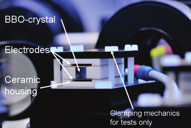
International Conference on Space Optics—ICSO 2020
                Virtual Conference
                30 March–2 April 2021

                                                                             Edited by Bruno Cugny, Zoran Sodnik, and Nikos Karafolas

              Optical and optomechanical design of the MERLIN laser optical
              bench

                                      International Conference on Space Optics — ICSO 2020, edited by Bruno Cugny, Zoran Sodnik,
                                                Nikos Karafolas, Proc. of SPIE Vol. 11852, 118522Q · © 2021 ESA and CNES
                                                          CCC code: 0277-786X/21/$21 · doi: 10.1117/12.2599445

                                                                       Proc. of SPIE Vol. 11852 118522Q-1
Downloaded From: https://www.spiedigitallibrary.org/conference-proceedings-of-spie on 10 Sep 2021
Terms of Use: https://www.spiedigitallibrary.org/terms-of-use
ICSO 2020                                                                                                 Virtual Conference
                   International Conference on Space Optics                                                               30 March-2 April 2021

                                       Optical and Optomechanical Design of the MERLIN
                                                      Laser Optical Bench
                                        M. Livrozeta*, B. Gronloha, H. Faidela, J. Luttmanna, D. Hoffmanna,
                               a
                                 Fraunhofer Institute for Laser Technology, Steinbachstr. 15, 52074 Aachen, Germany

                                                                                   ABSTRACT

                    For the satellite-based methane lidar instrument MERLIN a reliable laser source is needed that emits laser pulses at two
                    wavelengths of around 1645 nm to measure the methane concentration of earth’s atmosphere with an Integrated Path
                    Differential Absorption LIDAR (IPDA). To generate those pulses, the laser (LASO) consists of a seeded, actively q-
                    switched, diode pumped Nd:YAG master oscillator power amplifier (MOPA) and a subsequent seeded and frequency-
                    controlled optical parametric oscillator (OPO).
                    Due to the passive thermal control of the instrument the laser has to withstand a large non-operational and operational
                    temperature range and also high mechanical loads while at the same time a compact envelope is required. Together with
                    the demanding requirements on the laser performance a very robust optical design is needed.
                    To meet those requirements, Fraunhofer Institute for Laser Technology (ILT) uses optomechanical mounts that were
                    developed in a previous project and show very low tilting over a large operational temperature range, even after non-
                    operational temperature cycling and applying mechanical loads. The mounts are soldered and free of organic substances
                    as the LASO is enclosed in a pressurized housing (LASH). Any outgassing could lead to a decay or damage of the optics
                    and thus a failure of the laser.
                    During the development of the optomechanical mounts many tests were performed to quantify the statistical behavior
                    under mechanical and thermal loads. Based on those results and additional mechanical simulations, Monte-Carlo-Analyses
                    have been performed to analyze the performance of the laser and to verify the fulfilment of the requirements.
                    Keywords: MERLIN instrument, optical design, LIDAR, spaceborne Laser, Nd:YAG Laser, OPO, single-frequency,
                    soldered optics

                                                                           1. INTRODUCTION
                    The Methane Remote Sensing LIDAR Mission (MERLIN) is a cooperation between the French Space Agency CNES and
                    the German Space Administration DLR. With the Integrated Path Differential Absorption LIDAR (IPDA) of the instrument
                    the methane concentration and the temporal and local gradients in the earth‘s atmosphere shall be measured during the
                    mission duration of 3.25 years. An overview of the mission and the instrument design can be found in [1][2] and [3].
                    The MERLIN LIDAR employs a Nd:YAG laser with a following optical parametric oscillator (OPO) as light source. The
                    laser emits double pulses with two wavelengths around 1645 nm: The wavelength of one of these pulses is at a broadened
                    absorption feature of methane (lambda_on = 1645.5516 nm) while the other wavelength is close to a local minimum of
                    atmospheric absorption (lambda_off = ~1645.825 nm). With the known absorption coefficients for both wavelengths, the
                    absolute integrated methane concentration can be derived from the difference between the backscattered signals. The main
                    advantage of this setup is that with the laser as active light source no external illumination is required so that it can operate
                    during night and day and even through thin cloud layers.
                    In this paper, we present the optical and optomechanical design of the laser optical bench (LASO) as well as tests and
                    analyses that were conducted on the performance. Those results were part of the Critical Design Review (CDR), which
                    was successfully completed in 09/2020.

                    *marie.livrozet@ilt.fraunhofer.de; phone +49 241 8906 8010; ilt.fraunhofer.de

                                                                       Proc. of SPIE Vol. 11852 118522Q-2
Downloaded From: https://www.spiedigitallibrary.org/conference-proceedings-of-spie on 10 Sep 2021
Terms of Use: https://www.spiedigitallibrary.org/terms-of-use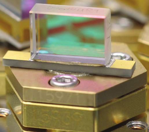
ICSO 2020                                                                                                                                      Virtual Conference
                   International Conference on Space Optics                                                                                                    30 March-2 April 2021

                                                                                           2. LASO CONCEPT
                    2.1 System Overview
                    The laser optical bench will be mounted in a pressurized laser housing (LASH) with three isostatic mounts at the
                    interfaces. This housing will be provided by the instrument prime Airbus Defence and Space GmbH. Within the housing
                    the pressure will be around 1000 mbar and dry air will be used as gas. The design of the housing was successfully tested
                    on the FULAS laser [4].
                    The optical bench consists of a baseplate with optical elements on both sides (see Figure 1). The LASO itself does not
                    include any electronics or active controls, but an electrical harness is required to deliver the different electrical currents,
                    voltages and signals. Those inputs are provided by the Laser Electronics (LAE). A dedicated thermal harness is used for
                    direct heat transfer from heat sources inside the laser to the instrument’s cooling system. In absence of an active thermal
                    control for the laser baseplate, the thermal harness is thermally decoupled from any structural element of the laser.

                                                                   LASO

                                                                                                                                     LASH

                          Figure 1. Model of LASO and LASH
                    To monitor the optical pulse energies at different stages within the laser and deliver the optical signals, that are used for
                    the control of the laser, fibers are used. Those fibers are connected to the Frequency reference unit (FRU), which also
                    delivers the seed signals for the laser and the OPO. The schematic interfaces of the three modules LASO, LAE and FRU
                    are shown in Figure 2.

                                                         Pockels
                                                                     Piezo     OSC Cavity                         AMP Power
                                                           Cell                                                                Piezo Voltage
                                                                    Voltage   Control Signal                       Monitor
                                                         Voltage                                                                   (LAE)
                                                                     (LAE)        (LAE)                             (LAE)
                                                          (LAE)

                                      Laser Housing („LASH“))

                                         Transfer              Oscillator       Transfer                           Transfer
                        Seed-laser                                                               Amplifier Slab                OPO („OP-R-“)     Transfer Optics
                                          Optics              Resonator          Optics                              Optics
                         1064 nm                                                               („A-S-“) 1064 nm                  1645 nm           („OP-OO-“)
                                         („O-S-“)          („O-R-“) 1064 nm    („O-OA-“)                           („A-AO-“)
                          (FRU)

                                                           Oscillator Pump                     Amplifier Pump
                                                                                                                               Transfer Optics
                                                           („O-P-“) 808 nm                     („A-P-“) 808 nm
                                                                                                                                  („OP-S-“)

                                                                                                                                 Seed-laser
                                                                               OSC Power         AMP Pump
                                                          OSC Pump current                                                        1645 nm
                                                                                Monitor           current
                                                                (LAE)                                                              (FRU)
                                                                                 (LAE)             (LAE)

                          Figure 2. Detailed functional block diagram of optical and electrical functions in LASO.

                                                                                    Proc. of SPIE Vol. 11852 118522Q-3
Downloaded From: https://www.spiedigitallibrary.org/conference-proceedings-of-spie on 10 Sep 2021
Terms of Use: https://www.spiedigitallibrary.org/terms-of-use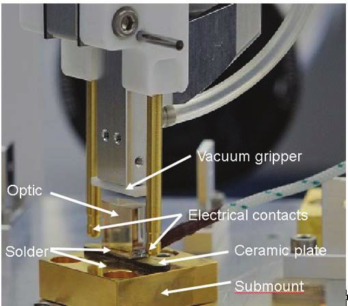
ICSO 2020                                                                                                    Virtual Conference
                   International Conference on Space Optics                                                                  30 March-2 April 2021

                    The housing includes all feedthroughs that are necessary to deliver the mentioned inputs and outputs.

                    2.2 Major design requirements
                    For the IPDA measurements the laser output beam of the LASO has to meet several optical requirements. The basic ones
                    are listed in Table 1.

                                               Parameter                       Required output
                                               Pulse energy                    >9 mJ
                                               Repetition rate                 20 Hz double pulse = 40 Hz single pulse
                                               Output wavelengths             Online: 1645.5516 nm
                                                                               Offline: 1645.8183 nm < Ȝ < 1645.8326 nm
                                               Pulse width                     >10 ns
                                               Spectral purity                 >99.95 %
                          Table 1. Basic optical requirements for LASO.

                    Besides those basic but still demanding requirements, also the stability of the output beam has to fulfill a number of
                    specifications concerning e.g. the pointing of the beam on different time scales. The main requirements are listed in Table
                    2. All those requirements include possible systematic deviations between online and offline pulses.
                                  Parameter                                                                     Maximum variation
                                  Beam pointing stability                                                       < 750 μrad
                                  Beam divergence                                                               < 11 %
                                  Systematic beam pointing difference between online/offline pulse              < 40 μrad
                          Table 2. Optical stability requirements for LASO.

                    Besides those optical requirements that are derived from the measurement principle and the telescope optics, several
                    constraints have an impact on the optomechanical and thus optical design of the laser: One major design constraint for the
                    MERLIN instrument is the passive thermal control that leads to a large operational temperature range between 15°C and
                    28°C. At the same time the design has to be compact and lightweight due to the overall restrictions for the whole instrument.
                    The laser has to withstand demanding mechanical loads such as shock up to 270 g and random vibrations of up to
                    19.6 g(rms) in the range 20 Hz to 2 kHz. Additionally, pressure and temperature changes as well as gravitational force
                    change the interface loads that are applied on the baseplate by the housing. LASH.
                    To meet the lifetime requirement (mission duration >3.25 years), avoiding of Laser-Induced Contamination (LIC) is of
                    crucial importance inside the sealed and pressurized laser housing. For that reason, optical mounting is achieved by
                    soldering and also the electrical harness is built up using soldering technology only. In doing so, any outgassing caused
                    by cable shielding or glue residues is avoided entirely.

                                                                       Proc. of SPIE Vol. 11852 118522Q-4
Downloaded From: https://www.spiedigitallibrary.org/conference-proceedings-of-spie on 10 Sep 2021
Terms of Use: https://www.spiedigitallibrary.org/terms-of-use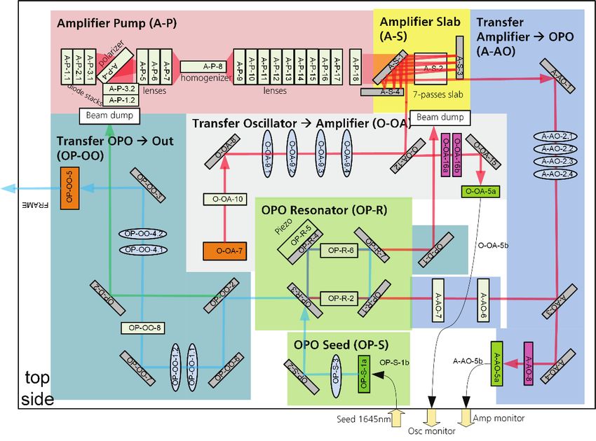
ICSO 2020                                                                                              Virtual Conference
                   International Conference on Space Optics                                                            30 March-2 April 2021

                                                                          3. OPTICAL DESIGN
                    3.1 Oscillator
                    The master oscillator is on one side of the LASO baseplate. The functional design is shown in Figure 3 with color coding
                    for different sections. The active medium is Nd:YAG and as in the FULAS laser the oscillator crystal is pumped from
                    both sides with diodes emitting at 808 nm that are mounted in two fiber-coupled pump modules [4]. The pump section is
                    marked in purple.

                          Figure 3. Block diagram of the oscillator side of LASO

                    To reach the high spectral purity requirements for the OPO signal beam it is necessary to reach very good spectral
                    properties of the OPO pump and therefore with the oscillator output beam. Especially the spectral purity and thus the
                    side mode suppression is crucial. Those requirements are reached with the help of a cavity dither control of the resonator
                    length. For this cavity control an injection seed laser at the laser wavelength is used (green section) that is provided by
                    the FRU. The beam is coupled into the resonator (yellow section) via a thin film polarizer and the resonator length is
                    being varied with the help of a piezo element on one end mirror to determine the optimal position of the mirror. For the
                    pulse emission the piezo is set to that position and the q-switch is activated, that is implemented with a Pockels cell made
                    of a BBO crystal.
                    The beam is coupled out via a partially reflective mirror and the generated pulses have a pulse energy of > 4.8 mJ and a
                    duration of 14.5 ns. As in the beam path of the seed laser a Faraday isolator is implemented behind the oscillator to avoid
                    disturbances by back reflections that could lead to a decrease of the spectral properties and in the worst case to the
                    destruction of the oscillator.

                    3.2 Amplifier
                    The amplifier is positioned on the other side of the baseplate together with the OPO. A periscope is used to guide the
                    beam from the oscillator side to the amplifier side. The block diagram of the second side of the baseplate is shown in
                    Figure 4.

                                                                       Proc. of SPIE Vol. 11852 118522Q-5
Downloaded From: https://www.spiedigitallibrary.org/conference-proceedings-of-spie on 10 Sep 2021
Terms of Use: https://www.spiedigitallibrary.org/terms-of-use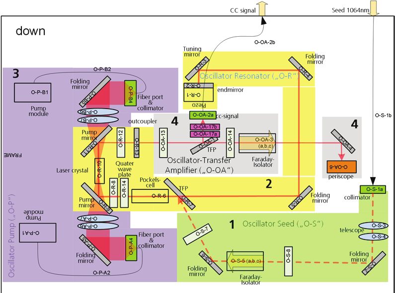
ICSO 2020                                                                                            Virtual Conference
                   International Conference on Space Optics                                                          30 March-2 April 2021

                          Figure 4. Block diagram of the amplifier/OPO side of LASO

                    For the amplifier, the InnoSlab design is applied. This concept is ideal for high energy and high efficiency single mode
                    power amplifiers. The Nd:YAG crystal is pumped from one side with high-power diode stacks and several additional
                    beam forming optics to optimize the pump geometry in the crystal (pink section). The limited space for the pump optics
                    is especially challenging and had a strong impact not only on the optics design but also on the required optical mounting
                    system.
                    The beam coming from the oscillator is first shaped with a cylindrical telescope and then folded seven times through the
                    slab-crystal (concept see Figure 5).
                    By choosing the correct beam shaping and slab mirror design the beam is widened with every pass in slow axis so that
                    the efficiency is optimized and the fluence kept constant and below the damage threshold.

                                                 Pump light
                                                  (808 nm)
                                                                                                            Resonator
                          Oscillator                                                                         mirror
                           beam

                                  Resonator
                                   mirror                                  InnoSlab                            To OPO
                                                                         Nd:YAG crystal
                          Figure 5. Schematic of folded signal beam path in InnoSlab crystal

                                                                       Proc. of SPIE Vol. 11852 118522Q-6
Downloaded From: https://www.spiedigitallibrary.org/conference-proceedings-of-spie on 10 Sep 2021
Terms of Use: https://www.spiedigitallibrary.org/terms-of-use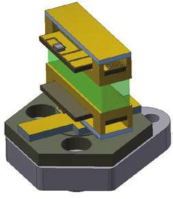
ICSO 2020                                                                                             Virtual Conference
                   International Conference on Space Optics                                                           30 March-2 April 2021

                    With the input signal of 4.8 mJ coming from the oscillator the amplifier can generate an output in the range of 30 mJ to
                    35 mJ, depending on the exact input requirements of the OPO. The main advantages of this amplifier design are a
                    comparably high efficiency of around 25 % and thus less heat loads, and no thermal lensing in the critical plane of the
                    OPO. Following the amplifier an additional telescope and waveplate are used to shape the beam to the requirements of
                    the OPO.

                    3.3 OPO
                    For the frequency conversion to the absorption line of methane an OPO is implemented. It consists of two KTP crystals
                    in a ring resonator (green section in Figure 4). The design of the OPO is based on a concept by DLR IPA [6] and has
                    been optimized with the help of a simulation model developed by ILT to increase the efficiency, fit the optical
                    parameters and the mechanical boundary conditions.
                    The frequency conversion is performed in the X-Z-plane of the crystals so that pump (1064 nm) and signal (1645 nm)
                    have a polarization parallel to the laser bench and the idler (3010 nm) polarization is perpendicular to that plane. As the
                    spectral properties of the signal beam are very important, the phase mismatch has to be minimized for both online and
                    offline wavelength. To allow this precise phase matching despite the large operational temperature range, both crystal
                    mounts have a temperature control.
                    One other important parameter is the systematic pointing difference between pulses of the two signal wavelengths, as
                    this has a direct impact on the measurement precision. The initial optical design showed a pointing difference in the
                    range of ~350 μrad, which was too large as a value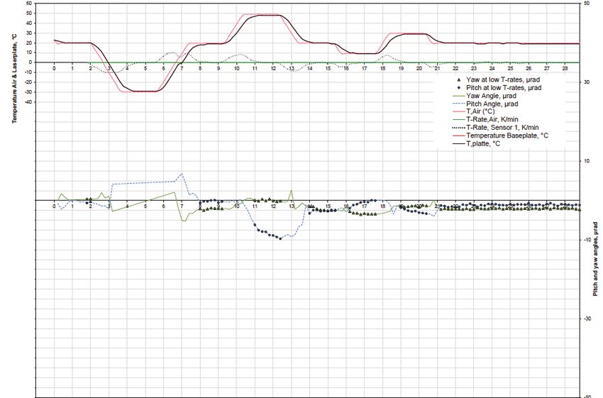
ICSO 2020 Virtual Conference
International Conference on Space Optics 30 March-2 April 2021
Figure 6. Photo of the MERLIN LASO Breadboard setup.
This setup was used to verify that all optical requirements that do not mainly depend on those stabilities can be met with
using the LAE and FRU as controls. All requirements listed in Table 1 were successfully verified, which includes the
important spectral purity requirement.
Due to the instability of the system it was difficult to measure the pointing stabilities which includes the low systematic
pointing difference between online and offline pulse. But it could be shown that within the general pointing instability of
the breadboard, no difference between the pointing of the two signals beams could be found with the breadboard.
4. OPTOMECHANICAL MOUNTS
The optomechanical mounts must meet the following requirements to ensure safe and stable long-term operation of the
laser system:
low tilting during environmental loads
no component outgassing
multiple adjustment during assembly (re-melting of the solder joint)
compact design
compensation of the different thermal expansion coefficients between base plate and optical components
interchangeability of the mounts during assembly
The basic types of mounts that are used in MERLIN and their design features are described below. All mounts including
their variations have been developed in the frame of the OPTOMECH projects and, except the KTP mount, were
successfully pre-tested within the FULAS project [4],[5].
4.1 Composite-Mount
The composite mount (C-mount) is most often used within the MERLIN LASO. The presented C-mount is the basic
design for optical mounts. Several other optical mounts were developed e.g. for periscope optics or spherical lenses and
are based on the same design. The recurrent task for all optomechanical mounts is to join optical materials such as
quartz, BK7 or SF6 to a laser base plate made of aluminum. The physical properties, especially the thermal expansion
coefficients of these materials, are very different and have to be compensated to reach the high stabilities. This
compensation is accomplished by an optimized composition of materials in-between the optical component and the laser
base plate as well as by design elements. A picture of a basic C-mount is shown in Figure 7.
Proc. of SPIE Vol. 11852 118522Q-8
Downloaded From: https://www.spiedigitallibrary.org/conference-proceedings-of-spie on 10 Sep 2021
Terms of Use: https://www.spiedigitallibrary.org/terms-of-use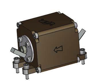
ICSO 2020                                                                                            Virtual Conference
                   International Conference on Space Optics                                                          30 March-2 April 2021

                          Figure 7. Photo of a basic C-Mount.

                    The C-mount was realized by means of Fraunhofer ILT’s Pick & Align resistance soldering technique. A crucial element
                    in this process is the active alignment of optical components in the solder pool. A six-axis manipulator enables the
                    components to be positioned with extreme precision during the soldering process. To further increase the strength and
                    reproducibility of the joint produced, the soldering technique was investigated in terms of long-term stability and
                    positional accuracy. In particular, surface properties and metallization of the joining partners decisively influence the
                    joint and must be tailored to thermal and mechanical stresses. In addition, various solder geometries were investigated in
                    order to optimize the positional accuracy of optical components both during the soldering process and once exposed to
                    the environment.

                    Figure 8. Adjustable Pick&Align mirror on a submount and details of the mounting tool

                    The most critical stability requirements within the MERLIN LASO regarding position accuracy between optics and laser
                    base plate have to be fulfilled in the oscillator and the OPO. The deviations from the alignment position shall be smaller
                    than ±10μrad after non-operational thermal loads and during operational thermal and mechanical loads. Measurements
                    show that the C-mount exhibits an alignment stability of the optical component up to the possible accuracy of
                    measurement for the arrangement in the climate chamber while thermal cycling. An exemplary test result for a C-Mount
                    exposed to temperatures from -30°C to 50°C is shown in Figure 8.

                                                                       Proc. of SPIE Vol. 11852 118522Q-9
Downloaded From: https://www.spiedigitallibrary.org/conference-proceedings-of-spie on 10 Sep 2021
Terms of Use: https://www.spiedigitallibrary.org/terms-of-use
ICSO 2020 Virtual Conference
International Conference on Space Optics 30 March-2 April 2021
Figure 9. Exemplary thermal cycle test with a Composite-Mount; pitch angle (blue), yaw angle (green) dependent on
temperature
4.2 Faraday Isolator
The Faraday isolator includes a magnetic field assembly and two optical inserts with a TGG crystal (see Figure 9). The
magnets inside the housing are encapsulated by a tube around the free aperture and the housing provides fittings between
the individual sections to avoid particle transmission.
Figure 10. CAD Model of a Faraday Isolator.
The optical inserts are designed in accordance with the same design principles as for the C-Mount: A suitable material
pairing reduces the mechanical stress in the optical components due to CTE mismatch. All parts of the insert are soldered
so that all components are fixed without glue. Both inserts can be rotated to align the Faraday isolator. After the alignment
is finished, the inserts can be fixed on the housing of the magnetic field assembly by bolts.
Proc. of SPIE Vol. 11852 118522Q-10
Downloaded From: https://www.spiedigitallibrary.org/conference-proceedings-of-spie on 10 Sep 2021
Terms of Use: https://www.spiedigitallibrary.org/terms-of-useICSO 2020 Virtual Conference
International Conference on Space Optics 30 March-2 April 2021
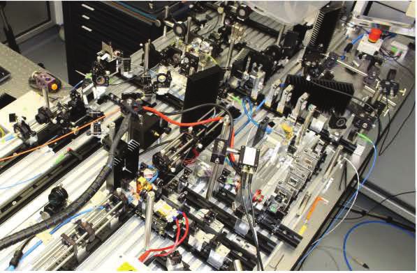
4.3 Pockels Cell
In addition to the mounting of the BBO crystal, the high electrical voltage represents a challenge for the design of the
Pockels cell. To prevent any flashover occurrence, design criteria like geometry, metallization, material selection and
manufacturing processes were considered. The resulting Pockels cell design consists of a metallized BBO crystal, two
metallized electrical contacts and four metallized housing parts made of ceramic. The electrical contacts additionally
perform the function of the mechanical mount of the BBO crystal.
Figure 11. Picture of the Pockels cell.
This assembly (Figure 10) is joined to an optomechanical mount similar to the C-mount by the Pick&Align soldering
process. Besides the mechanical interface to the laser plate, the Pockels cell mount features electrical transfer interfaces to
the harness of the laser system.
4.4 KTP Crystal Mount
The KTP crystal mount is used in the OPO, in which two KTP crystal-mounts with different crystal lengths are included
(see section 3.3). The KTP crystal mount consists of a KTP oven and an optomechanical sub-mount as basis. The sub-
mount acts as a mechanical holder and also provides an electrical transfer interface for the thermal control. Each KTP oven
consists of two heater bars and a KTP crystal soldered between them (see Figure 11). Each heater bar has a heater plate
integrated by a soldering technique. In addition, the upper heater plate features a temperature sensor for thermal control.
The design of the heater bar contributes to a homogeneous heat distribution within the KTP crystal due to reduced contact
area to the mounting plate. For mounting or gripping purposes each heater bar contains a mounting plate.
Heater plates
Heater bars
KTP crystal
Figure 12. KTP crystal-Mount (without electrical contacts)
Proc. of SPIE Vol. 11852 118522Q-11
Downloaded From: https://www.spiedigitallibrary.org/conference-proceedings-of-spie on 10 Sep 2021
Terms of Use: https://www.spiedigitallibrary.org/terms-of-useICSO 2020 Virtual Conference
International Conference on Space Optics 30 March-2 April 2021
5. ANALYSES
There are two mechanisms that lead to a misalignment of the laser beam: The variation of mechanical loads at the
interfaces to LASH and the change of the LASO baseplate temperature.
5.1 Interface Loads LASH/LASO
The interface loads change due to the change of the difference between inner and outer pressure of the housing, the
orientation and magnitude of the gravity vector and temperature changes with respect to the integration temperature. All
those changes appear on different time scales as on long-term scale for ground-to-orbit effects or on mid-term scales for
one orbit or one month.
A mechanical analysis was performed to calculate the effect those interface loads have on the baseplate at the position of
each optical mount. Based on the results the tilting of each mount was derived for each possible combination of interface
loads.
5.2 C-Mount thermomechanical stability
To analyze the effect of the baseplate temperature variation on the alignment, results from the OPTOMECH project were
used. Prior to its integration each mount was tested in the climate chamber and the tilting was observed before and after a
non-operational cycle and during an operational cycle. Compared to MERLIN the temperature ranges were a bit larger
with a non-operational range of -30 °C to 50 °C and an operational range of 10 °C and 30 °C, so the data can be seen as
worst case. The example of a measurement result is shown in Figure 9.
Overall 35 mounts were tested and based on previous analyses only those with a tilting ofICSO 2020 Virtual Conference
International Conference on Space Optics 30 March-2 April 2021
5.5 Results of the performance analysis
To compare the analysis results with the requirements, the different effects have to be combined. The operational and
non-operational thermal loads are assumed to be statistically independent effects. The deviations in output parameters
caused by them are added geometrically. The effect of interface loads is considered as a constant shift of each optic and
is added linearly to the thermal loads.
For both mid-term time scales (one orbit and one month) the calculations show compliance to the requirements on all
calculated output requirements. No short-term changes are expected.
The major results for the long-term scale are listed in Table 4.
Table 4. Results of optical performance analysis for long term time scale for online / offline wavelength
Parameter Interface loads After non- Thermal Total Requirement
operational long-term
temperature variation
cycle ±6.5 K
Beam pointing stability / μrad 31 / 30 347 / 353 257 / 262 463 / 470 < 750
Beam divergence horizontal / % 0.6 / 0.5 3.1 / 3.6 3.3 / 3.7 5.1 / 5.7 < 11
Systematic beam pointing 4 10 11 21 < 40
difference between
online/offline pulse / μrad
All parameters for the long-term scale are well within the requirements although the inputs and calculations are considered
worst case.
6. CONCLUSION
In this paper we presented the optical design of the MERLIN laser and the optomechanical design of the basic mounts
that are used within the laser. Additionally, we explained the analyses, that were executed to show the performance of
the laser with those mounts under the defined environmental loads. The results show that the requirements on the output
beam will be fulfilled.
The CDR of the MERLIN LASO was completed successfully in September 2020 including the presented designs and
analyses.
7. ACKNOWLEDGEMENTS
The R&D project underlying the report, »MERLIN Phase C/D«, has been carried out on behalf of the Federal Ministry
for Economic Affairs and Energy BMWi under the grant number 50EP1601. The work in »MERLIN« is being carried
out on behalf of the DLR Space Administration, subcontracted by Airbus Defence and Space GmbH in phases C/D.
The authors would like to thank the whole MERLIN project team at DLR, CNES, Airbus DS, SpaceTech GmbH, von
Hoerner & Sulger GmbH and Fraunhofer ILT, for their continuous support and their fruitful cooperation in this
challenging project. In particular, we would like to thank Dimitrios Kokkinos, Hans Huber, Matthias Winzen, Dominik
Esser and Jochen Wüppen.
Proc. of SPIE Vol. 11852 118522Q-13
Downloaded From: https://www.spiedigitallibrary.org/conference-proceedings-of-spie on 10 Sep 2021
Terms of Use: https://www.spiedigitallibrary.org/terms-of-useICSO 2020 Virtual Conference
International Conference on Space Optics 30 March-2 April 2021
REFERENCES
[1] C. Stephan et al., “MERLIN - a space-based methane monitor”, Lidar Remote Sensing for Environmental
Monitoring XII, Proc. of SPIE, Vol. 8159, (2011)
[2] 3)ODPDQW*(KUHW%0LOOHW0$OSHUV³0(5/,1
D)UHQFKဨ*HUPDQPLVVLRQDGGUHVVLQJPHWKDQH monitoring
by LIDAR from space”, Proc. of 26th ILRC, Porto Heli, Greece, (2012).
[3] Christian Wührer, Christopher Kühl, Stefano Lucarelli, M. Bode, "MERLIN: overview of the design status of the
lidar Instrument," Proc. SPIE 11180, International Conference on Space Optics — ICSO 2018, 1118028 (12 July
2019);
[4] Sven Hahn, Markus Bode, Jörg Luttmann, Dieter Hoffmann, „FULAS: High energy laser source for future
LIDAR applications” Proceedings of ICSO 2018, Crete, Greece Oct. 2018.
[5] J. Löhring, M. Winzen, H. Faidel, J. Miesner, D. Plum, J. Klein, O. Fitzau, M. Giesberts, W. Brandenburg, A.
Seidel, N. Schwanen, D. Riesters, S. Hengesbach, H.-D. Hoffmann, "Key optical components for spaceborne
lasers," Proc. SPIE 9730, Components and Packaging for Laser Systems II, 97300O (22 April 2016);
[6] Andreas Fix, Christian Büdenbender, Martin Wirth, Mathieu Quatrevalet, Axel Amediek, Christoph Kiemle,
Gerhard Ehret, "Optical parametric oscillators and amplifiers for airborne and spaceborne active remote sensing
of CO2 and CH4," Proc. SPIE 8182, Lidar Technologies, Techniques, and Measurements for Atmospheric
Remote Sensing VII, 818206 (30 September 2011)
Proc. of SPIE Vol. 11852 118522Q-14
Downloaded From: https://www.spiedigitallibrary.org/conference-proceedings-of-spie on 10 Sep 2021
Terms of Use: https://www.spiedigitallibrary.org/terms-of-useYou can also read