PRT168M - OPERATION MANUAL POWER TROWELS RIDE ON - Paclite Equipment
←
→
Page content transcription
If your browser does not render page correctly, please read the page content below

OPERATION MANUAL

POWER TROWELS RIDE ON

     PRT168M

       Uni-corp Europe
     PACLITE Equipment
     12 avenue des Coquelicots
     94380 Bonneuil sur Marne
              France

    www.paclite-equip.com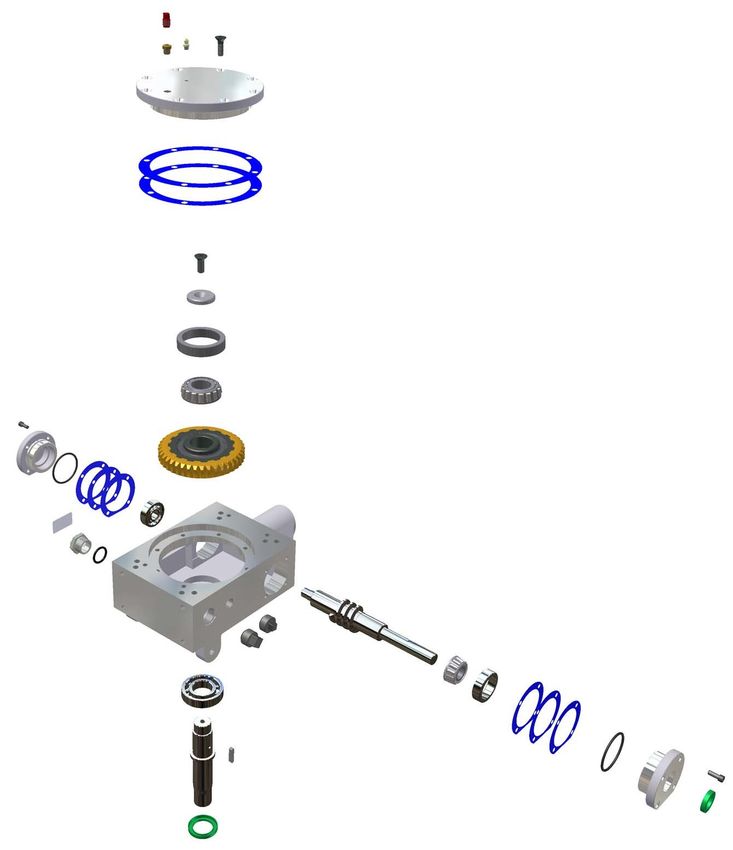
2020

   EC DECLARATION OF CONFORMITY I DECLARATION CE DE
CONFORMITE I DECLARACIÓN DE CONFORMIDAD CE I DECLARAÇÃO
                  CE DE CONFORMIDADE

     We, PACLITE EQUIPMENT, ZAC des petits Carreaux, 12 Avenue des Coquelicots, 94380 Bonneuil sur Marne, France, hereby certify
     that if the product described within this certificate is bought from an authorised Paclite dealer within the EEA, it conforms to the
     following directives: Machinery Directive 2006/42/EC, Electromagnetic Compatibility Directive 2004/108/EC (as amended by
     92/31/EEC & 93/68 EEC). The physical agent (vibration) conforms with the directive 2002/44/EC. The low voltage directive
     2006/95/EC, BS EN ISO 12100-1/2 Safety of machinery and associated harmonised standards, where applicable. Noise emissions
     conform to directive 2005/88/EC Annex VI), for machines under article 12 the notified body is TÜV Rheinland Product Safety
     GmbH - Am Grauen Stein - D- 51105 Köln, Germany.

     Nous soussignons, PACLITE EQUIPMENT, ZAC des petits Carreaux, 12 Avenue des Coquelicots, 94380 Bonneuil sur Marne, France,
     certifions que si le produit décrit dans ce certificat est acheté chez un distributeur de la marque déposée “Paclite” au sein de la EEA,
     celui-ci est conforme aux norms CEE ci-après: Norme de la machine 2006/42/CE, Norme compatible pour l’électromagnétisme
     2004/108/CE (modifie par 92/31/CEE et 93/68/CEE). Le nombre de vibrations est en accord avec la directive 2002/44/CE.
     Caractéristiques basse tension 2006/95/CEE, BS EN ISO 12100-1/2 , Norme de sécurité des machines et des critères associés et
     configurés, si applicable. Les émissions debruit sont conformes à la directive 2005/88/CE Annexe VI pour machines, article 12.
     L’objet mentionné est TÜV Rheinland Product Safety GmbH - Am Grauen Stein - D-51105 Köln, Allemagne.

     La Sociedad, PACLITE EQUIPMENT, ZAC des petits Carreaux, 12 Avenue des Coquelicots, 94380 Bonneuil sur Marne, Francia, por el
     presente documento certifica que si el producto descrito en este certificado es comprado a un distribuidor autorizado de Paclite en
     la EEA, este es conforme a las siguientes directivas: 2006/42/CE de la CEE, Directiva 2004/108/CEE sobre Compatibilidad
     Electromagnética (según enmiendas 92/31/CEE y 93/68 CEE). El numero de vibraciones esta de acuerdo con la Directiva
     2002/44/CE. Directiva sobre Bajo Voltaje 2006/95/CEE, BS EN ISO 12100-1/2 de Seguridad de Maquinaria y Niveles armonizados
     estándares asociados donde sean aplicables. Emisión de Ruídos conforme a la Directiva 2005/88/CE Anexo VI para máquinas bajo
     articulo 12 la mencionada unidad está TÜV Rheinland Product Safety GmbH - Am Grauen Stein - D-51105 Köln, Germany.

     Noi, PACLITE EQUIPMENT, ZAC des petits Carreaux, 12 Avenue des Coquelicots, 94380 Bonneuil sur Marne, Francia, attestiamo che
     se il prodotto descritto nel presente certificato è acquistato da un rivenditore Paclite autorizzato all'interno del SEE, è conforme alle seguenti
     direttive: Direttiva macchine 2006 / 42 / CE, Direttiva sulla compatibilità elettromagnetica 2004/108 / CE (modificata dalla 92/31 / CEE e
     93/68 / CEE). L'agente fisico (vibrazione) è conforme alla direttiva 2002/44 / CE. Direttiva sulla bassa tensione 2006/95 / CE, BS EN ISO
     12100-1 / 2 Sicurezza delle macchine e relative norme armonizzate, ove applicabile. Le emissioni sonore sono conformi alla direttiva
     2005/88 / CE allegato VI), per le macchine di cui all'articolo 12 l'organismo notificato è TÜV Rheinland Product Safety GmbH - Am Grauen
     Stein - D- 51105 Köln, Germania..

     PRODUCT TYPE……                           TYPE DE PRODUIT….                       TIPO DE PRODUCTO..                    TIPO DE PRODUCTO..

     MODEL……………….                             MODELE……………...                          MODELO……………...                        MODELO……………...

     SERIAL No…………..                          Nº DE SERIE………….                        Nº DE SERIE………….                      Nº DE SÉRIE………….

     DATE OF                                  DATE DE                                 FECHA DE                              DATA DE

     MANUFACTURE…….                           FABRICATION……….                         FABRICACIÓN……….                       FABRIC……………….
     WEIGHT………………                             POIDS…………………                            PESO…………………                           PESO……………….…

Signed by:                                                         Quality Manager - On behalf of Uni-corp Europe
Signature:                                                         Directrice de Qualité - au nom de Uni-corp

                                                                   Europe S.A.R.L.
                         Anita Tan
This manual, or a copy of it, must be kept with the machine at all times.
There is a manual storage container located on the machine for your
convenience.

                                                                            055763; 06/11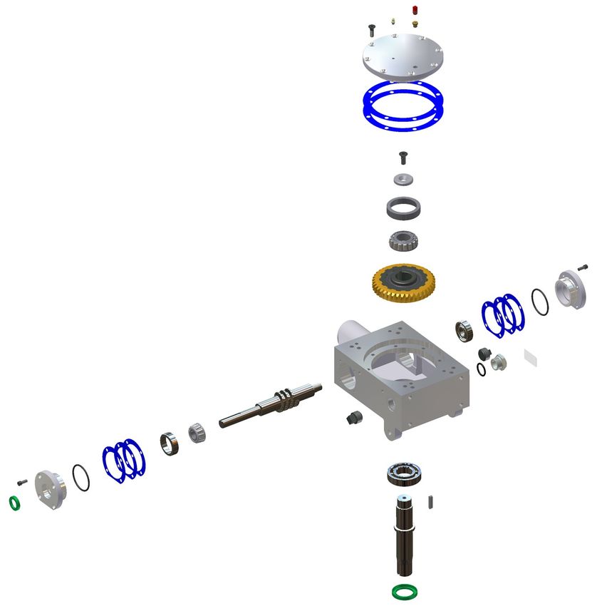
Riding Trowel
OPERATIONS-PARTS MANUAL
    This manual covers the Riding Trowels listed below:
     Part No.                Description
    PRT168M                 R/O Trowel, Twin 90cm, mechanical

Copyright © 2011
Uni-Corp Europe PACLITE Equipment
All rights reserved

All information, specifications, and illustrations in this manual are subject to change without notice and are based on
the latest information at the time of publication. No part of this manual may be reproduced or transmitted in any form
or by any means, electronics or mechanical, for any purpose, without the express written permission of
Uni-Corp Europe PACLITE Equipment. Uni-Corp Europe PACLITE Equipment assumes no responsibility or liability
for any errors or inaccuracies that may appear in this manual.

PACLITE Products are covered under one or more of the following patent
numbers:
U.S. Design Patents: 344,736; 400,542; 400,544; 402,998; 402,999; 403,332; 404,041; 404,042; 410,931; 413,127;
416,564; 465,897; 466,909; 474,203.
U.S. Utility Patents: 5,108,220; 5,238,323; 5,328,295; 5,352,063; 5,405,216; 5,476,342; 5,480,257; 5,480,258;
5,533,831; 5,562,361; 5,567,075; 5,613,801; 5,658,089; 5,685,667; 5,803,658; 5,816,739; 5,816,740; 5,890,833;
5,934,823; 5,967,696; 5,988,938; 5,988,939; 6,019,433; 6,019,545; 6,048,130; 6,053,660; 6,089,786; 6,106,193;
6,857,815; 5,288,166; 6,582,153 B1, 7,108,449; 7,114,876; 7,316,523; 7,690,864 B2
Canadian Patents: 2,039,893.
With other Patents Pending

First Issue: June 2011
Uni-Corp Europe PACLITE Equipment Manual Part No.: 055763
Printed in France.
055763; 06/11                                                                                                       i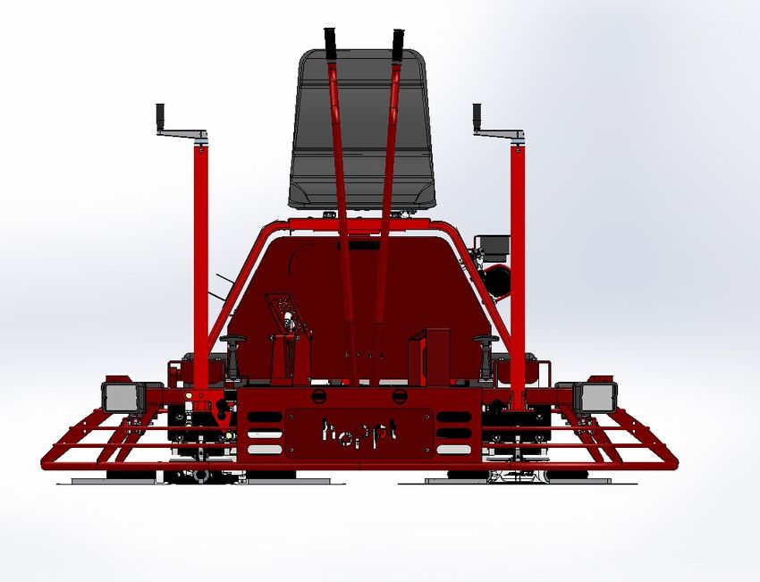
Limited Warranty

     LIMITED WARRANTY and LIMITATION OF LIABILITY

     PACLITE warrants its products to be free of defects in material or workmanship for the followingperiods:

               A. New Machines and Parts .......................... One Year
               B. New Gear Boxes ........................................ Two Years

     The above listed warranty periods are effective for +RSSW Machines with a first day of use by End User on April 1, 2007 or later.

     Warranty period begins on first day of use by End User. This first day of use is established by the date of a completed
     PACLITE Warranty Card or a Bill of Sale to the End User. All warranty is based on the following limited warranty terms and
     conditions, including the disclaimer of implied warranties and consequential damages.

1. PACLITE's obligation and liability under this warranty is limited to repairing or replacing parts if, after PACLITE's inspection,
there is determined to be a defect in material or workmanship. PACLITE reserves the choice to repair or replace.

2. If PACLITE chooses to replace the part, it will be at no cost to the customer and will be made available to the PACLITE
Distributor, Dealer, or Rental Center from whom the End User purchased the product.

3. Replacement or repair parts, installed in the product, are warranted only for the remainder of warranty period of the product as
though they were the original parts.

4. PACLITE does not warranty engines. Engine warranty claims should be made directly to an authorized factory service center
for the particular engine manufacturer.

5. PACLITE's warranty does not cover the normal maintenance of products or its components (such as engine tune-ups and oil &
filter changes). The warranty also does not cover normal wear and tear items (such as belts and consumables).

6. PACLITE's warranty will be void if it is determined that the defect resulted from operator abuse, failure to perform normal
maintenance on the product, modification to product, alterations or repairs made to the product without the written approval of
PACLITE. PACLITE specifically excludes from warranty any damage to any trowels resulting from an impact to the rotors.

7.    Impact damage is not covered under the PACLITE Gear Box warranty.

8. PACLITE will pay shop labor on warranty items at the PACLITE Shop Labor Rate in existence on the date of the warranty
claim. A PACLITE Labor Chart will determine the time allowed to complete a repair and will govern the shop labor hours that will be
allowed.

9. PACLITE will pay freight on warranty replacement parts at worldwide standard ground rates. No warranty replacement parts will
be shipped air freight at the expense of PACLITE. PACLITE only pays outbound freight charges when sending warranty
replacement parts to the customer via ground service. PACLITE does not pay any inbound freight. However, if PACLITE determines
this to be a warranted item, only then will PACLITE reimburse the customer for inbound freight at standard ground rates.

10. PACLITE'S WARRANTY POLICY WILL NOT COVER THE FOLLOWING: TAXES; SHOP SUPPLIES; ENVIRONMENTAL
SURCHARGES;AIR FREIGHT; TRAVEL TIME; LOSS OF TIME; INCONVENIENCE; LOSS OF RENTAL REVENUE; RENTAL
COSTS OF EQUIPMENT USE REPAIRED; LOSS OF USE OF THE PRODUCT; COMMERCIAL LOSS; OR ANY OTHER
CHARGES WHATSOEVER ORANY LIABILITIES FOR DIRECT, INCIDENTAL, OR CONSEQUENTIAL DAMAGE OR DELAY.

11. PACLITE MAKES NO OTHER WARRANTY, EXPRESSED OR IMPLIED. THIS LIMITED WARRANTY IS IN LIEU OF THE
WARRANTY OF MERCHANTABILITY AND FITNESS. THERE ARE NO OTHER WARRANTIES THAT EXTEND BEYOND THE
DESCRIPTION ON THIS DOC

12. No PACLITE employee or representative is authorized to change this warranty in any way or grant any other warranty unless
such change is made in writing and signed by an officer of PACLITE.

ii                                                                                                                                       055763; 06/11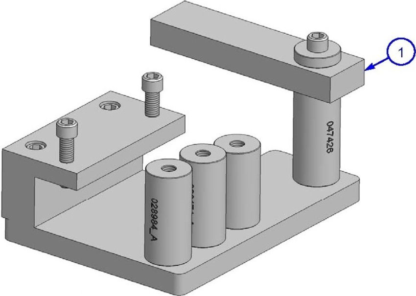
Table of Contents

Sect No.        Title                                                                                                 Page

...             Limited Warranty . . . . . . . . . . . . . . . . . . . . . . . . . . . . . . . . . . . . . . . . . . . . .ii
...             Information Contained In This Manual . . . . . . . . . . . . . . . . . . . . . . . . . . . .v
...             Dealer Information . . . . . . . . . . . . . . . . . . . . . . . . . . . . . . . . . . . . . . . . . . .vi
...             Ordering Parts . . . . . . . . . . . . . . . . . . . . . . . . . . . . . . . . . . . . . . . . . . . . .vii
...             Model Number - Serial Number Codes . . . . . . . . . . . . . . . . . . . . . . . . . .viii
...             Unit Identification . . . . . . . . . . . . . . . . . . . . . . . . . . . . . . . . . . . . . . . . . . . .ix
...             Technical specifications . . . . . . . . . . . . . . . . . . . . . . . . . . . . . . . . . . . . . . .x
...             Engine Specifications . . . . . . . . . . . . . . . . . . . . . . . . . . . . . . . . . . . . . . . .xvi
...             Machine Dimensional Specifications . . . . . . . . . . . . . . . . . . . . . . . . . . . .xiii
...             Sound And Vibration Specifications . . . . . . . . . . . . . . . . . . . . . . . . . . . . .xiv

1.0             Safety . . . . . . . . . . . . . . . . . . . . . . . . . . . . . . . . . . . . . . . . . . . . . . . . . . .1-1
...             State Regulations . . . . . . . . . . . . . . . . . . . . . . . . . . . . . . . . . . . . . . . . . .1-2
...             Federal Regulations . . . . . . . . . . . . . . . . . . . . . . . . . . . . . . . . . . . . . . . .1-3
1.1             General Safety Precautions . . . . . . . . . . . . . . . . . . . . . . . . . . . . . . . . . .1-4
1.2             Spark Arrestor Notice . . . . . . . . . . . . . . . . . . . . . . . . . . . . . . . . . . . . . . .1-5
1.3             Operating Safety . . . . . . . . . . . . . . . . . . . . . . . . . . . . . . . . . . . . . . . . . . .1-6
1.4             Engine Safety . . . . . . . . . . . . . . . . . . . . . . . . . . . . . . . . . . . . . . . . . . . . .1-8
1.5             Servicing Safety . . . . . . . . . . . . . . . . . . . . . . . . . . . . . . . . . . . . . . . . . . .1-9
1.6             Safety And Operation Labels . . . . . . . . . . . . . . . . . . . . . . . . . . . . . . . .1-10

2.0             Operations . . . . . . . . . . . . . . . . . . . . . . . . . . . . . . . . . . . . . . . . . . . . . . .2-1
2.1             Introduction . . . . . . . . . . . . . . . . . . . . . . . . . . . . . . . . . . . . . . . . . . . . . . .2-3
2.2             Start Up Procedures . . . . . . . . . . . . . . . . . . . . . . . . . . . . . . . . . . . . . . . .2-4
2.3             Operating Instructions . . . . . . . . . . . . . . . . . . . . . . . . . . . . . . . . . . . . . . .2-6

3.0             Service . . . . . . . . . . . . . . . . . . . . . . . . . . . . . . . . . . . . . . . . . . . . . . . . . .3-1
3.1             Periodic Maintenance . . . . . . . . . . . . . . . . . . . . . . . . . . . . . . . . . . . . . . .3-2
3.2             Trowel Gearbox . . . . . . . . . . . . . . . . . . . . . . . . . . . . . . . . . . . . . . . . . . . .3-3
3.3             Drive Belt . . . . . . . . . . . . . . . . . . . . . . . . . . . . . . . . . . . . . . . . . . . . . . . .3-4
3.4             Control Lever Adjustment . . . . . . . . . . . . . . . . . . . . . . . . . . . . . . . . . . . .3-8
3.5             Right Hand Control Lever Adjust . . . . . . . . . . . . . . . . . . . . . . . . . . . . .3-10
3.6             Lift Lever Adjustment . . . . . . . . . . . . . . . . . . . . . . . . . . . . . . . . . . . . . .3-12
3.7             Transporting Trowel . . . . . . . . . . . . . . . . . . . . . . . . . . . . . . . . . . . . . . .3-14
3.8             Battery Jump Start . . . . . . . . . . . . . . . . . . . . . . . . . . . . . . . . . . . . . . . .3-18

055763; 06/11                                                                                                                     iii
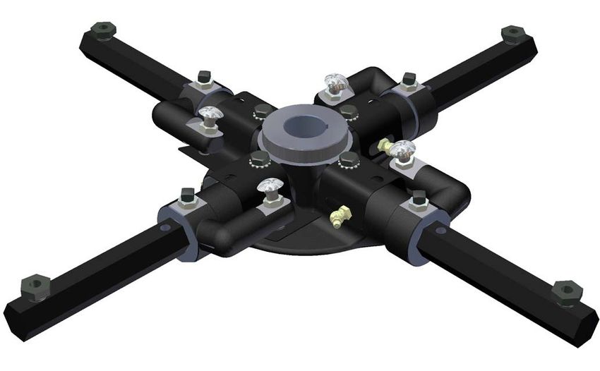
Table of Contents, continued

4.0    Parts . . . . . . . . . . . . . . . . . . . . . . . . . . . . . . . . . . . . . . . . . . . . . . . . . . . .4-1
...    Factory Service Information . . . . . . . . . . . . . . . . . . . . . . . . . . . . . . . . . .4-2
...    Replacement Part Procedure . . . . . . . . . . . . . . . . . . . . . . . . . . . . . . . . .4-3
4.1    Seat Frame Assembly . . . . . . . . . . . . . . . . . . . . . . . . . . . . . . . . . . . . . . .4-4
4.2    Mainframe Assembly . . . . . . . . . . . . . . . . . . . . . . . . . . . . . . . . . . . . . . . .4-6
4.3    Steering Assembly . . . . . . . . . . . . . . . . . . . . . . . . . . . . . . . . . . . . . . . . .4-8
4.4    Spray System . . . . . . . . . . . . . . . . . . . . . . . . . . . . . . . . . . . . . . . . . . . .4-10
4.5    Pitch Control Assembly . . . . . . . . . . . . . . . . . . . . . . . . . . . . . . . . . . . . .4-12
4.6    Engine System Assembly . . . . . . . . . . . . . . . . . . . . . . . . . . . . . . . . . . .4-14
4.7    Driveline Assembly . . . . . . . . . . . . . . . . . . . . . . . . . . . . . . . . . . . . . . . .4-16
4.8    Electrical Schematic . . . . . . . . . . . . . . . . . . . . . . . . . . . . . . . . . . . . . . .4-18
4.9    Right Rotor Assembly (SOM) . . . . . . . . . . . . . . . . . . . . . . . . . . . . . . . .4-20
4.10   Left Rotor Assembly (SOM) . . . . . . . . . . . . . . . . . . . . . . . . . . . . . . . . .4-22
4.11   Right Spider Assembly . . . . . . . . . . . . . . . . . . . . . . . . . . . . . . . . . . . . .4-24
4.12   Left Spider Assembly . . . . . . . . . . . . . . . . . . . . . . . . . . . . . . . . . . . . . .4-26
4.13   Right Gearbox Assembly (SOM) . . . . . . . . . . . . . . . . . . . . . . . . . . . . . .4-28
4.14   Left Gearbox Assembly (SOM) . . . . . . . . . . . . . . . . . . . . . . . . . . . . . . .4-30
4.15   Dolly Jack Assembly . . . . . . . . . . . . . . . . . . . . . . . . . . . . . . . . . . . . . . .4-32
4.16   Pans and Lifting Bridle . . . . . . . . . . . . . . . . . . . . . . . . . . . . . . . . . . . . .4-34
4.17   Tools . . . . . . . . . . . . . . . . . . . . . . . . . . . . . . . . . . . . . . . . . . . . . . . . . . .4-36

iv                                                                                                       055763; 06/11
Information Contained in this
                                  Manual

This manual provides information and procedures to safely operate and maintain the
PACLITE Machine.

For your own safety and protection from personal injury, carefully read, understand, and observe
the safety instructions described in this manual. Keep this manual or a copy of it with the machine
at all times.

Always operate this machine in accordance with the instructions described in this manual. A well
maintained piece of equipment will provide many years of trouble free operation.

This manual is divided into the following sections:

                        SECTION 1                      SECTION 2
                         SAFETY                       OPERATIONS

                        SECTION 3                       SECTION 4
                         SERVICE                         PARTS

Complete any warranty requirements as specified by the engine manufacturer in their instructions
found inside the manual tube located on the side of the seat frame.

Your engine and clutch is not manufactured by PACLITE, and therefore is not covered under the

Uni-Corp Europe PACLITE Equipment

Your engine manufacturer should be contacted if you wish to purchase a parts manual or a repair
manual for your engine.

Refer to enclosed owners engine manual for complete O&M instructions. See your battery
manufacturer for battery warranty.

055763; 06/11                                                                                   v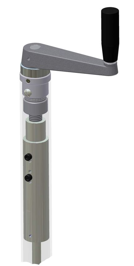
Dealer Information

 Your Dealer has PACLITE trained mechanics and original PACLITE replacement
 parts. Always contact the PACLITE Dealer who sold you this machine for PACLITE
 Certified repairs and replacement parts.

Place PACLITE Dealer information below for future reference.

  Dealer Name:

  Phone #: (     )-       -

 Address:

  City:                                                State:         Zip:

  Salesman:                                            Mobile Phone

 Additional Comments:

vi                                                                           055763; 06/11

Ordering Parts

Section 4.0 contains illustrated parts lists for help in ordering replacement parts for your machine.
Follow the instructions below when ordering parts to insure prompt and accurate delivery:

       1.     All orders for service parts - include the serial number for the machine. Shipment
              will be delayed if this information is not available.

       2.     Include correct description and part number from the “PARTS” section of this
              manual.

       3.     Specify exact shipping instructions, including the preferred routing and complete
              destination address.

       4.     DO NOT return parts to PACLITE without receiving written authorization from
              PACLITE. All authorized returns must be shipped pre-paid.

       5.     When placing an order, please contact the PACLITE dealer nearest you.

                  All information, specifications, and illustrations in this manual
                        are subject to change without notice and are based
                         on the latest information at the time of publication.

055763; 06/11                                                                                      vii
Model Number - Serial Number
Codes
Manufacturer’s Codes:
When ordering parts or requesting service information, you will always be asked to specify the
model and serial numbers of the machine. The legends below specifically defines each significant
character or group of characters of the Model Number and Serial Number codes.
Model Number
PRT 168- M
MODEL
SERIES
Serial Number
The serial number found on the identification plate is a ten digit format. The model number
identifies your machine and will ensure that you receive the correct replacement parts.
HA1 12 09 01
Production Sequence
Month Mfd
Year Mfd
Series/Model
viii 055763; 06/11Unit Identification
Unit Identification Plate Location:
An identification plate listing the model number and the serial number is attached to each unit and
is located on the left side front deck of mainframe. Refer to Figure 1 for serial number and model
number location. This plate should not be removed at any time.
Please record the information found on this plate below so it will be available should the
identification plate become lost or damaged. When ordering parts or requesting service
information, you will always be asked to specify the model and serial numbers of the machine.
FILL IN FOR FUTURE REFERENCE
Model Number:
Serial Number:
Date Purchased:
Purchased From:
MODEL SERIES
SERIAL NU MBE R
Figure 1
Serial Number Location
055763; 06/11 ixTechnical Specifications
Measurements in this manual are in U.S. units and their customary metric units (i.e., metric units
contained within brackets [8 mm]). The machine RIGHT-HAND and LEFT-HAND sides are deter-
mined by sitting on machine (SOM) facing in the direction the machine will travel when going for-
ward.
Machine Features:
• Dimensions (L x W x H) inch [mm] . . . . . . . . . . . . . . . . . .77.5x40.5x54
(guard rings/top of seat) . . . . . . . . . . . . . . . . . . . . . . . . . .[1969x1029x1372]
• MACHINE Weight lb [kg]
WITH HONDA GX690 . . . . . . . . . . . . . . . . . . . 737[335]
• Panning Path Width inch [mm] . . . . . . . . . . . . . . . . . . . . .71.2 [1808]
• Two Rotors (Diameter) inch [mm] . . . . . . . . . . . . . . . . . . .36 [914]
• Rotor Speed (RPM) . . . . . . . . . . . . . . . . . . . . . . . . . . . . . .110 - 135
• Finish Blade (8) inch [mm] . . . . . . . . . . . . . . . . . . . . . . . .6 x 14 [152.4x355.6]
• Gearbox (2) . . . . . . . . . . . . . . . . . . . . . . . . . . . . . . . . . . . .Standard Duty (STD)
• Fixed Guard Rings . . . . . . . . . . . . . . . . . . . . . . . . . . . . . .Standard
• Fixed Seat Frame . . . . . . . . . . . . . . . . . . . . . . . . . . . . . . .Standard
• Powered Retardant Spray System . . . . . . . . . . . . . . . . . .Standard
• Spray System Capacity gal [L] . . . . . . . . . . . . . . . . . . . . .6 [23]
• Steering System . . . . . . . . . . . . . . . . . . . . . . . . . . . . . . . .Dual Levers
• Gearbox Rotation . . . . . . . . . . . . . . . . . . . . . . . . . . . . . . .Standard
• Battery . . . . . . . . . . . . . . . . . . . . . . . . . . . . . . . . . . . . . . . .12 Volt
• Safety Shutdown Switch . . . . . . . . . . . . . . . . . . . . . . . . . .Seat Controlled
• Fuel Capacity gal [L] . . . . . . . . . . . . . . . . . . . . . . . . . . . . .6 [23]
• Run Time (Approximate) hr . . . . . . . . . . . . . . . . . . . . . . . .2.5
x 055763; 06/11Technical Specifications, continued • Transmission Type . . . . . . . . . . . . . . . . . . . . . . . . . . . . . .Torque Converter Clutch • Drive Belt Type . . . . . . . . . . . . . . . . . . . . . . . . . . . . . . . . .Kevlar Cogged Vee • Hour Meter Type . . . . . . . . . . . . . . . . . . . . . . . . . . . . . . . .Digital Read-out 055763; 06/11 xi
Engine Specifications

    Honda Engine Information

    •     Model . . . . . . . . . . . . . . . . . . . . . . . . . . . . . . . . . . . . . . . . . . . . . . . . . .GX-690 R TDW
    •     Rated Power hp [kW] @ 3,600 RPM . . . . . . . . . . . . . . . . . . . . . . . . .22.3 [16.6]

    •     Displacement in³ [cm³] . . . . . . . . . . . . . . . . . . . . . . . . . . . . . . . . . . . . .42 [688]

    •     Dimensions (L x W x H) inch [mm] . . . . . . . . . . . . . . . . . . . . . . . . . . .15.9x16.1x17.2 [405x410x438]

    •     Fuel (Type) . . . . . . . . . . . . . . . . . . . . . . . . . . . . . . . . . . . . . . . . . . . . .Regular unleaded gasoline

    •     Weight (Dry) lb [kg] . . . . . . . . . . . . . . . . . . . . . . . . . . . . . . . . . . . . . . .98 [44.4]

•

    xii                                                                                                                               055763; 06/11
Machine Dimensional
Specifications
All information, specifications, and illustrations on this page in this manual are subject to
change without notice and are based on the latest information at the time of publication.
[1350 mm]
HEIGHT
[1980 mm]
LENGTH
[1040 mm]
WIDTH
055763; 06/11 xiiiCE Sound And Vibration Data
Sound Pressure Level Information:
Sound pressure is "A" weighted . Measured at the operators ear position while the ride-on trow-
el is operating at full throttle on concrete in a manner most often experienced in “normal ” circum-
stances. Sound pressure may vary depending upon the condition of the concrete. Hearing
protection is always recommended.
Vibration Level Information:
The vibration level indicated is the maximum RMS (Root Mean Square) velocity value obtained
at the handle grip while operating the ride-on trowel on curing concrete in a manner most often
experienced in “normal ” circumstances. Values were obtained from all three axes of motion. The
values shown represent the maximum RMS value from these measurements.
Summary Data Of Sound And Vibration Testing for CE Marking
Distant Seat Foot Hand
Test Engine Operator Sound
Sound Vibration Vibration Vibration
Machine Type Ear SPL Power Level
Press Overall Overall Maximum
dB (A) dB (A) dB (A) m/sec² m/sec² m/sec²
MP215 Honda
55 86.9 86.8 2.76 5.73 3.00
This information was acquired from sound and vibration analysis tests conducted at
Allen Engineering Corporation test facilities.
xiv 055763; 06/11Section 1
SAFETY
055763; 06/11 1-1SECTION 1 State Regulations
SAFETY
CALIFORNIA PROPOSITION 65
WARNING
Gasoline engine exhaust from this product contains chemicals
known to the State of California to cause cancer, birth defects and
other reproductive harm.
1-2 055763; 06/11Federal Regulations SECTION 1
SAFETY
SILICOSIS WARNING
Grinding/cutting/drilling of masonry, concrete, metal and other
materials with silica in their composition may give off dust or
mists containing crystalline silica. Silica is a basic component
of sand, quartz, brick clay, granite and numerous other miner-
als and rocks. Repeated and/or substantial inhalation of air-
borne crystalline silica can cause serious or fatal respiratory
diseases, including silicosis. In addition, California and some
other authorities have listed respirable crystalline silica as a
substance known to cause cancer. When cutting such materi-
als, always follow the respiratory precautions mentioned
above.
RESPIRATORY HAZARDS
Grinding/cutting/drilling of masonry, concrete, metal and other
materials can generate dust, mists and fumes containing
chemicals known to cause serious or fatal injury or illness,
such as respiratory disease, cancer, birth defects or other
reproductive harm. If you are unfamiliar with the risks associ-
ated with the particular process and/or material being cut or
the composition of the tool being used, review the material
safety data sheet and/or consult your employer, the material
manufacturer/supplier, governmental agencies such as OSHA
and NIOSH and other sources on hazardous materials.
California and some other authorities, for instance, have pub-
lished lists of substances known to cause cancer, reproduc-
tive toxicity, or other harmful effects.
Control dust, mist and fumes at the source where possible. In
this regard use good work practices and follow the recom-
mendations of the manufacturers or suppliers, OSHA/NIOSH,
and occupational and trade associations. Water should be
used for dust suppression when wet cutting is feasible. When
the hazards from inhalation of dust, mists and fumes cannot
be eliminated, the operator and any bystanders should
always wear a respirator approved by NIOSH/MSHA for the
materials being used.
055763; 06/11 1-3SECTION 1 1.1
SAFETY General Safety Precautions
1.1.1 Safety-Alert Signs
This manual contains Safety-Alert Signs, as defined below, which must be followed to
reduce the possibility of improper service damage to the equipment or personal
injury. Read and follow all Safety-Alert Signs included in this manual.
NOTE defines an operating procedure,
condition, etc. which is essential to
highlight that contains useful or
important information.
EMERGENCY is used for the identification of safety equipment,
first aid, or emergency egress locations.
NOTICE used to convey safety information on labels and signs.
CAUTION is indicative of a potentially hazardous situation which,
if not avoided, may result in minor or moderate injury.
Potentially hazardous situations that could result in death
or serious injury are indicated by the word WARNING.
DANGER indicates an imminently hazardous situation which,
if not avoided, will result in death or serious injury.
1-4 055763; 06/111.2 SECTION 1
Spark Arrestor Notice SAFETY
1.2.1 Laws Pertaining to Spark Arrestors
Some states require that in certain locations arrestors be used on internal
combustion engines. A spark arrester is a device designed to prevent the discharge
of spark or flames from the engine exhaust. It is often required when operating
equipment on forested land to prevent the risk of fires. Consult the engine distributor
or local authorities and make sure that you comply with regulations regarding spark
arrestors.
055763; 06/11 1-5SECTION 1 1.3
SAFETY Operating Safety
1.3.1 Operating Safety
Familiarity and proper training are required for the safe operation of this equipment!
Equipment operated improperly or by untrained personnel can be dangerous! Read
the operating instructions contained in both this manual and the engine manual and
familiarize yourself with the location and proper use of all controls.
1.3.2 NEVER operate this machine in applications for which it is not intended.
1.3.3 NEVER allow anyone to operate this equipment without proper training. People
operating this equipment must be familiar with the risks and hazards associated with
it.
1.3.4 NEVER touch the engine or muffler while the engine is on or immediately after it has
been turned off. These areas get hot and may cause burns.
1.3.5 NEVER use accessories or attachments that are not recommended by PACLITE.
Damage to equipment and injury to the user may result.
1.3.6 NEVER operate the machine with the beltguard missing. Exposed drive belt and
pulleys create potentially dangerous hazards that can cause serious injuries.
1.3.7 NEVER leave machine running unattended.
1.3.8 DO NOT run the machine indoors or in an enclosed area such as a deep trench
unless adequate ventilation, through such items as exhaust fans or hoses, is
provided. Exhaust gas from the engine contains poisonous carbon monoxide gas;
exposure to carbon monoxide can cause loss of consciousness and may lead to
death.
1.3.9 ALWAYS remain aware of moving parts and keep hands, feet, and loose clothing
away from the moving parts of the equipment.
1.3.10 ALWAYS keep hands, feet, and loose clothing away from moving parts of the
machine.
1.3.11 ALWAYS read, understand, and follow procedures in the Operator’s Manual before
attempting to operate the equipment.
1.3.12 ALWAYS be sure operator is familiar with proper safety precautions and operation
techniques before using machine.
1-6 055763; 06/111.3, continued SECTION 1
Operating Safety SAFETY
1.3.13 ALWAYS close fuel valve on engines equipped with one when machine is not being
operated.
1.3.14 ALWAYS store the equipment properly when it is not being used. Equipment should
be stored in a clean, dry location out of the reach of children.
1.3.15 ALWAYS operate the machine with all safety devices and guards in place and in
working order.
055763; 06/11 1-7SECTION 1 1.4
SAFETY Engine Safety
1.4.1 Engine Safety
Internal combustion engines present special hazards during operation
and fueling. Read and follow the warning instructions in the engine
owner’s manual and the safety guidelines below. Failure to follow the
warnings and safety guidelines could result in severe injury or death.
1.4.2 DO NOT run the machine indoors or in an enclosed area such as a deep trench
unless adequate ventilation, through such items as exhaust fans or hoses, is
provided. Exhaust gas from the engine contains poisonous carbon monoxide gas;
exposure to carbon monoxide can cause loss of consciousness and may lead to
death.
1.4.3 DO NOT smoke while operating the machine.
1.4.4 DO NOT smoke when refueling the engine.
1.4.5 DO NOT refuel a hot or running engine.
1.4.6 DO NOT refuel the engine near an open flame.
1.4.7 DO NOT spill fuel when refueling the engine.
1.4.8 DO NOT run the engine near open flames.
1.4.9 ALWAYS refill the fuel tank in a well-ventilated area.
1.4.10 ALWAYS replace the fuel tank cap after refueling.
1.4.11 ALWAYS keep the area around the muffler free of debris such as leaves, paper,
cartons, etc. A hot muffler could ignite the debris and start a fire.
1-8 055763; 06/111.5 SECTION 1
Service Safety SAFETY
1.5.1 Service Safety
Poorly maintained equipment can become a safety hazard! In order
for the equipment to operate safely and properly over a long period of
time, periodic maintenance and occasional repairs are necessary.
1.5.2 DO NOT attempt to clean or service the machine while it is running. Rotating parts
can cause severe injury.
1.5.3 DO NOT crank a flooded engine with the spark plug removed on gasoline-powered
engines. Fuel trapped in the cylinder will squirt out the spark plug opening.
1.5.4 DO NOT test for spark on gasoline-powered engines if the engine is flooded or the
smell of gasoline is present. A stray spark could ignite the fumes.
1.5.6 DO NOT use gasoline or other types of fuels or flammable solvents to clean parts,
especially in enclosed areas. Fumes from fuels and solvents can become explosive.
1.5.7 ALWAYS turn engine off and remove key from machine before performing
maintenance or making repairs.
1.5.8 ALWAYS handle blades carefully. The blades can develop sharp edges which can
cause serious cuts.
1.5.9 ALWAYS keep the area around the muffler free of debris such as leaves, paper,
cartons, etc. A hot muffler could ignite the debris and start a fire.
1.5.10 ALWAYS replace worn or damaged components with spare parts designed and
recommended by PACLITE.
1.5.11 ALWAYS disconnect the spark plug on machines equipped with gasoline engines,
before servicing, to avoid accidental start-up.
1.5.12 ALWAYS switch off the power supply at the battery disconnect before adjusting or
maintaining the electrical equipment.
1.5.13 ALWAYS keep the machine clean and labels legible. Replace all missing and hard-to
read labels. Labels provide important operating instructions and warn of dangers and
hazards.
055763; 06/11 1-9SECTION 1 1.6
SAFETY Safety and Operation Labels
The safety and operation labels shown in this section are placed in important areas on the
machine to draw attention to potential safety hazards and service information. Should any of
these labels become unreadable or damaged, replacement labels can be ordered from your
distributor.
This is a multi-purpose label that
requires the operator to have
maximum eye, hearing, hand, and feet
protection. Also, it highly recommends
that the operator reads the manual.
This label identifies the lift locations
on the machine. No other locations or
features on the machine are to be
used as lifting points. This will cause
damage to the machine.
This label identifies the tank used for retardant
spray agents (i.e., water-based retardants) only
on the machine. NO OTHER non-retardant
chemicals nor fuel is to be in this tank.
For gasoline-fueled machines, this label
identifies the tank used for GASOLINE
fuel only in the machine. NO OTHER
type of fuel is to be used in this tank.
1-10 055763; 06/111.6, continued SECTION 1
Safety and Operation Labels SAFETY
This label is a maintenance reminder to grease
the thrust bearing daily. This will ensure that the
life span of the bearings will be maintained at
their optimal performance level.
This label cautions against allowing cleaning agents,
surface treatments, or other foreign substances to
contaminate drive components.
The drive components could be damaged from the
contamintation and cause the drive system to fail.
055763; 06/11 1-11SECTION 1 1.6, continued
SAFETY Safety and Operation Labels
This label warns of the risk hazards associated
with engine exhaust fumes causing heath issues
as identified by the State of California.
1-12 055763; 06/11SECTION 2
OPERATIONS
Section 2
OPERATIONS
055763; 06/11 2-1SECTION 2
OPERATIONS
This machine is built with user safety in mind. However, it can present hazards if
improperly operated and serviced. Follow operating instructions carefully.
If you have any questions about operating or servicing this equipment,
please contact PACLITE Customer Service.
2-2 055763; 06/112.1 SECTION 2
Introduction OPERATIONS
2.1.1 Description
The PRT168M riding trowel is a modern high production machine. Finishing rates
will vary depending on the operators’ skill and job conditions. This riding trowel has
eight finishing blades.
The standard duty gearboxes are designed to provide exceptional performance
with low maintenance and trouble free use under some of the worst conditions.
All PACLITE PRT 168M are equipped with a safety shutdown switch and a low oil
warning light for added job safety and engine protection. Operating time between fuel
refills is approximately 2-1/2 to 3 hours with a rotor speeds of 110 to 135 RPM.
The PRT 168M are the most technically advanced riding trowels on the
market today. With proper maintenance and use, your riding trowel will provide you
with exceptional service and dependability.
055763; 06/11 2-3SECTION 2 2.2
OPERATIONS Start Up Procedures
2.9.1 Before Starting Procedures
Before starting the riding trowel check for the following:
1) Oil level in engine.
2) Oil level in riding trowel gearboxes.
3) Fuel level in fuel tank.
4) Condition of riding trowel arms and blades.
5) Verify that daily maintenance of grease points have been performed.
2.9.2 Starting Procedures
Before starting riding trowel, refer to Figure 2.2.1 and Figure 2.2.2 for location and
identification of operational and visual controls pertaining to the operation of the riding
trowel.
1) Sit down correctly on the riding trowel seat. DO NOT attempt to start the
riding trowel without an operator in the seat.
2) If engine is cold, pull out the choke lever located in the control zone (refer
to Figure 2.2.1). Press down on throttle pedal (located by the operator's
right foot) one to two times.
Too much throttle during start-up will flood the engine.
3) Turn ignition switch key to the start-position, immediately release key when
engine starts. If after two or three attempts the engine has not started push in
choke. Attempt to start trowel again. Allow engine to warm up for 5 minutes
before operating riding trowel.
Operating the starter for more than 5 seconds can damage
the starter or engine. If engine fails to start release the switch
and wait 15 seconds before operating starter again.
2-4 055763; 06/112.2, continued SECTION 2
Start Up Procedures OPERATIONS
12V Accessory
LOW OIL LIGHT
LIGHT SWITCH
KEY SWITCH
HOURMETER
ENGINE CHOKE
FIGURE 2.2.1
TOP VIEW OF CONTROLS
055763; 06/11 2-5SECTION 2 2.3
OPERATIONS Operating Instructions
2.3.1 Operating The Riding Trowel
To utilize your PACLITE PRT 168MRider to its fullest capacity the
machine should be driven in the direction the operator is facing. This will
finish the widest possible area while giving the operator an excellent view
of the slab surface about to be troweled. When the machine reaches the
end of the slab make a 180 degree turn and repeat the straight line of
direction to the other end of the slab. To familiarize a new operator with
the riding trowel the following steps should be taken.
All items in this manual are described from the
operator Sitting On Machine or SOM for short.
1) Location of all Operating Controls
[A] Right Pitch Control
[B] Joystick (Forward & Reverse)
[C] Joystick (Left & Right, Forward & Reverse)
[D] Left Pitch Control
[E] Right Foot - Throttle
[F] Left Foot Rest
[G] Seat Adjustment
[H] Tool Holder [B]
[C]
[D]
[G]
[A]
[H]
[F]
[E]
FIGURE 2.3.1
Operations Control Components
2-6 055763; 06/112.3, continued SECTION 2
Operating Instructions OPERATIONS
2) With the operator in the seat, show him the functions of the joysticks [B] and
[C] and how to start the machine. Refer to Figure 2.3.1.
A hard level concrete slab with water on the surface is an ideal place for an
operator to practice with the machine. For practice pitch the blades up
approximately 1/4 inch on the trailing edge. Start by making the machine
hover in one spot and then practice driving the machine in a straight line and
making 180 degree turns. Best control is achieved at full engine RPM.
After starting engine fully engage the throttle.
This allows the engine to warm up quicker and
also engages the centrifugal clutch. At this time
the machine’s rotors will begin turning.
DO NOT use excessive pressure on the joysticks.
Excessive pressure does not increase the reaction
time of the machine and can damage steering controls.
2.3.2 Stopping The Riding Trowel
To stop the trowel’s movement, let go of the joysticks [B] and [C]. They will return to
their neutral position. Also release pressure on the right foot pedal [E].
If in need of an emergency stop, simply turning the key
off or raising your left foot off the pedal will stop the engine from running.
055763; 06/11 2-7SECTION 2 2.3, continued
OPERATIONS Operating Instructions
2.3.3 Steering The Riding Trowel
A slight "feathering motion" forward and backward with the left hand joystick is
required to move the machine in a straight path to the left or right while operating the
right hand joystick. Refer to Figure 2.3.3..
Position Action
1 Forward
2 Reverse
3 Rotate clockwise
4 Rotate counter clockwise
5 Left sideways
6 Right sideways
FIGURE 2.3.3
Steering Control Diagram
2-8 055763; 06/112.3, continued SECTION 2
Operating Instructions OPERATIONS
2.3.4 Pitch Adjustment
Different pitch angles are needed as you work the different stages of the concrete.
Refer to Figure 2.3.4 table below. When changing or setting pitch (angle of trowel
blades), slow the machine down, set the desired degree of pitch on the left side of the
machine and then adjust the right side to match.
To increase the pitch, turn the pitch control clockwise “a” use the pitch indicator “b” to
adjust pitch equally on both right and left trowel blades.
FIGURE 2.3.4
Pitch Adjustment
055763; 06/11 2-9SECTION 2 2.3, continued
OPERATIONS Operating Instructions
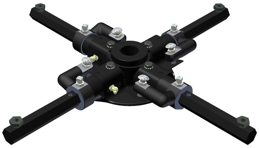
2.3.5 Steering Response Adjustment
There are three settings on this Riding Trowel for steering response. Some
operators like a fast response to steering while others would rather have a
slower response when pressure is applied to the operator joysticks. The
following illustrations show each appropriate setting on the lower control
arms to achieve the desired response.
NOTE: The faster setting makes the joysticks “tighter” to the operator and
more force will be required to move the joysticks.
Slow Response Setting
Normal Response Setting
Fast Response Setting
2-10 055763; 06/11SECTION 3
SERVICE
Section 3
SERVICE
055763; 06/11 3-1SECTION 3 3.1
SERVICE Periodic Maintenance
3.1 Periodic Maintenance Schedule
The table below list basic trowel and engine maintenance. Refer to OEM engine
manufacturer's Operation Manual for additional information on engine maintenance. A
copy of the engine operator's manual was supplied with the machine when it was
shipped. To service the engine pull the seat locking pin out and tilt seat back.
TABLE 3.1.1
CHECK LIST
EVERY EVERY EVERY EVERY
ITEM DAILY
20 HRS 50 HRS 100 HRS 300 HRS
Grease towel arms /
Check oil level in gearbox /
Check engine oil level /
Check & tighten external hardware /
Check drive belt for wear /
Check valve clearance /
Change engine oil /
Replace engine oil filter /
Grease trowel gearbox /
Replace spark plug /
3-2 055763; 06/113.2 SECTION 3
Trowel Gearbox SERVICE
3.2 Trowel Gearbox Maintenance
Check Oil levels in the gearbox daily (every 8 hours) Add oil if oil level is below the check
sight glass.
1) To add oil tilt gearbox to the side and remove the fill plug. Add oil through hole
opening. Replace fill plug after proper level has been achieved. Fill so that there is
oil 1/2 way in the sight glass. Use Gearbox Oil PN 048299 only.
2) Each Gearbox has a grease fitting on top cover that must be greased (2 SHOTS
ONLY) every 300 operating hours. Use only Mobilith SHC 220 Extended
pressure grease.
GEARBOX
TOP COVER
GREASE FITTING
FILL PLUG
FIGURE 3.2.1
FILL PLUG LOCATION
SIGHTGLASS
FIGURE 3.2.2
GREASE FITTING LOCATION
055763; 06/11 3-3SECTION 3 3.3
SERVICE Drive Belt
3.3.0 Drive Belt Maintenance
The drive belts MUST be free from oil and
foreign contaminants to prolong life.
3.3.1 To Replace The Drive Belt:
1) Place the trowel on a flat, level surface with the blades pitched flat.
2) Disconnect the battery. Refer to Figure 3.3.1.
3) Remove the clutch cover. Refer to Figure 3.3.2.
5) Remove tap bolt to remove driver pulley.
6) Loosen the set screws in the flex u-joint.
7) Slide the u-joint apart so belt will slide through.
8) Replace belt using PN 051332.
9) Repeat steps 7 through 2 in reverse order.
3-4 055763; 06/113.3, continued SECTION 3
Drive Belt SERVICE
MOVE POSITIVE
BATTERY CABLE
FIGURE 3.3.1
BATTERY DISCONNECT
055763; 06/11 3-5SECTION 3 3.3, continued
SERVICE Drive Belt
CLUTCH COVER DRIVEN PULLEY
BELT
BOLT DRIVELINE
FIGURE 3.3.2
BELT REPLACEMENT
3-6 055763; 06/113.3, continued SECTION 3
Drive Belt SERVICE
FLEX COUPLER
BEARING MOUNT HARDWARE
FIGURE 3.3.3
BELT REPLACEMENT
055763; 06/11 3-7SECTION 3 3.4
SERVICE Control Lever Adjustment
3.4 Control Lever Adjustment Procedure
Be sure that the trowel is on a level surface. The control levers should line up evenly.
If levers appear out of adjustment they can be re-adjusted forward or backwards as
follows:
Trowel must be placed on flat level surface that
fully supports the blades on both rotors.
1) Remove bolts and nuts [A].
2) Loosen jam nuts [B].
3) Extend linkage to adjust control levers backward.
4) Shorten linkage to adjust linkage control levers forward.
5) After levers have been adjusted to the desired position, reassemble bolts
and nuts [A] and tighten jam nuts [B].
3-8 055763; 06/113.4, continued SECTION 3
Control Lever Adjustment SERVICE
[B]
[A]
FIGURE 3.4.1
CONTROL LEVER ADJUSTMENT
055763; 06/11 3-9SECTION 3 3.5
SERVICE Right Hand Control Lever Adjust
3.5 RH Control Lever Adjustment Right Or Left Procedure
The right hand lever should be set to the same angle as that of the left to form a "V".
If levers become out of adjustment adjust the right h a n d lever as follows:
1) Remove jam nuts [D].
2) Remove bolt [C].
3) Extend linkage to move control levers to the right.
4) Shorten linkage to move control levers to the left.
5) After control lever has been adjusted to the desired position reassemble bolt
[C] and tighten jam nuts [D].
3-10 055763; 06/113.5, continued SECTION 3
Right Hand Control Lever Adjust SERVICE
“V” FORM
There should be a
10” gap at the top
of the joysticks.
JOYSTICK LOCATIONS
LOWER
CONTROL FIGURE 3.5.1
ARM “V” FORM ORIENTATION
[C]
[D]
[D]
LINKAGE
FIGURE 3.5.2
RIGHT HAND CONTROL ADJUSTMENT
055763; 06/11 3-11SECTION 3 3.6
SERVICE Lift Lever Adjustment
3.6 Lift Lever Adjustment Procedure
Damage to and/or replacement of a trowel arm can change the adjustment of the lift
lever. This can unbalance the trowel arms and cause the riding trowel to wobble
during operation. To operate smoothly the lift lever on all trowel arms must be
adjusted t h e same to ensure that the riding trowel is balanced correctly.
Adjusting the trowel arms is accomplished by using the optional trowel arm alignment
jig PN 016863. The service manual that is included with the alignment jig
describes in detail the steps to perform this procedure and to check the flatness and
straightness of the trowel arms.
The steps below describe the general procedure to remove the trowel arms to be
aligned.
Make sure that there is no pitch in the blades
before attempting to remove a trowel arm.
1) Block up pressure plate [A] using a wooden block.
2) Remove stabilizer ring from spider assembly (only on available models).
3) Remove blades from trowel arms.
4) Loosen hex head cap screw [B] and remove it and the external star washer
from the spider boss.
5) Remove trowel arms from spider boss with lift levers in place.
6) Clean flats on trowel arm before placing it in the trowel arm jig (PN 016863).
7) Perform the alignment procedures as outlined in the alignment jig service
manual (PN 047427).
8) Re-attach trowel arm to spider boss and blades to trowel arms.
9) Tighten down hex head cap screw to secure trowel arm in place.
10) Reattach stabilizer ring (only on available models).
3-12 055763; 06/113.6, continued SECTION 3
Lift Lever Adjustment SERVICE
TROWEL ARM
[A]
BLADE
FIGURE 3.6.1
PRESSURE PLATE LOCATION
[B]
SPIDER BOSS
FIGURE 3.6.2
FASTENER HARDWARE REMOVAL
055763; 06/11 3-13SECTION 3 3.7
SERVICE Transporting Trowel
3.7 Transporting Trowel Procedures
Optional dolly jacks are available for short moves or to aid in servicing the trowel.
Install dolly jacks as follows:
1) Inspect dolly jack for serviceability and damage.
2) Place riding trowel on firm level ground.
3) Tie steering levers [I] to frame to prevent them from tipping forward when
trowel is being lifted. PACLITE assumes no liability if injury occurs and this step
is eliminated during any trowel lifting procedures.
4) Insert the front dolly jack [J] fully into the holes in the mainframe of the riding
trowel. The front dolly jacks are equipped with short lifting tubes while the rear
dolly jacks have long lifting tubes.
5) Insert the rear dolly jack [M] with the long lifting tubes into the holes
provided in the rear of the mainframe. The holes in the mainframe are located
directly opposite the front holes.
6) Turn jack handles clockwise to lift trowels and counter-clockwise to lower
trowel. [I]
FIGURE 3.7.1
3-14 STEERING LEVER LOCATION 055763; 06/113.7, continued SECTION 3
Transporting Trowel SERVICE
[M]
[J]
FIGURE 3.7.2 FIGURE 3.7.3
FRONT DOLLY JACK REAR DOLLY JACK
LOCATION LOCATION
055763; 06/11 3-15SECTION 3 3.7, continued
SERVICE Transporting Trowel
The dolly jack lifting system is designed for short moves and
to aid in servicing the trowel. It is not a substitute for a
towing system or trailer. An optional lifting bridle [N]
is available and recommended for lifting the trowel.
Attach the bridle to each of the four lifting eyes [O]
on the trowel. Refer to Figure 3.7.7.
Secure steering levers to frame to prevent them
from tipping forward when the towel is being
lifted.
[N]
FIGURE 3.7.6
LIFTING BRIDLE
3-16 055763; 06/113.7, continued SECTION 3
Transporting Trowel SERVICE
FIGURE 3.7.7
[O] LIFTING HOOK LOCATION
055763; 06/11 3-17SECTION 3 3.8
SERVICE Battery Jump Start
3.9 Battery Jump Start Procedures
Occasionally it may be necessary to jump start a weak battery. If jump starting is
necessary the following procedure is recommended to prevent starter damage,
battery damage, and personal injury.
Jump starting a battery incorrectly can cause the battery
to explode resulting in severe personal injury or death.
Do not smoke or allow any ignition sources near the
battery and do not start a frozen battery.
Electrical arcing can cause severe personal injury.
Do not allow positive and negative cable ends to touch.
1) Use a battery of the same voltage (12V) as is used with your engine.
2) Attach one end of the positive booster cable (red) to the positive (+) terminal of
the booster battery. Attach the other end to the terminal of your engine battery.
3) Attach one end of the negative booster cable (black) to the negative (-)
terminal on the booster. Attach the other end of the negative cable to your
engine battery.
4) Jump starting in any other manner may result in damage to the battery or the
electrical system.
Over cranking the engine can cause starter damage.
Allow 5 minutes for starter to cool if engaged for more
than 15 seconds.
When using lights or high amperage draw accessories,
idle the engine for a period of 20 minutes to bring the
battery to charge state.
3-18 055763; 06/113.8, continued SECTION 3
Battery Jump Start SERVICE
BATTERY
FIGURE 3.8.1
BATTERY LOCATION
055763; 06/11 3-19SECTION Notes
SERVIC
3-20 055763; 06/11SECTION 4
PARTS
Section 4
PARTS
055763; 06/11 4-1SECTION 4 Factory Service Information
PARTS
This section contains the illustrated drawings and parts list for help in identifying and/or ordering
replacement parts for your machine. Follow the instructions in the front section of this manual
“Ordering Parts” when ordering replacement parts to insure prompt and accurate delivery.
The Right Hand (RH) and/or Left Hand (LH) orientations are defined from the operator’s view of
sitting on machine (SOM).
All set screws have blue (LOC-TITE™) applied at the
factory. If set screw is removed or loosened for any
reason re-apply blue (LOC-TITE™).
All grease fittings are capped with CAP PLUG GC-5
(PN 015692) to protect the fitting. If cap becomes
missing or damaged replace it as soon as possible.
Anti-Seize is applied at the factory to all drive line coupling,
gear box main and counter shafts and pitch control threaded
rod assemblies. If these parts are disassembled re-apply a light
coat of a graphite based anti-seize.
4-2 055763; 06/11Replacement Parts Procedures SECTION 4
PARTS
We recommend PACLITE quality replacement parts, available from the PACLITE Customer
Service Department or your nearest PACLITE Dealer.
Part numbers are subject to change without notice. Use part numbers listed in the applicable parts
table when you place your order. If a part number changes, the PACLITE Customer Service
Department or your nearest PACLITE dealer will have the latest part number for the replacement
part.
Remember when you order replacement parts, you will need your model number and serial
number. These are the numbers that you have recorded in the UNIT ID section of this
manual. Please order replacement parts by the appropriate part number, not the key number.
This manual contains an illustrated parts list for help in ordering replacement parts for your
machine. Follow the instructions below when ordering parts to insure prompt and accurate
delivery:
1. All orders for service parts - include the serial number for the machine. Shipment
will be delayed if this information is not available.
2. Include correct description and part number from the “PARTS” Section 4.
3. Specify exact shipping instructions, including the preferred routing and complete
destination address.
4. DO NOT return parts to PACLITE without receiving written authorization from
PACLITE. All authorized returns must be shipped pre-paid.
5. When placing an order, please contact the PACLITE Dealer nearest you.
All information, specifications, and illustrations in this manual
are subject to change without notice and are based
on the latest information at the time of publication.
055763; 06/11 4-3SECTION 4 4.1 Illustration
PARTS Seat Frame Unit
21
25
16
14 22
20
9
7
10
17
26
8 15
4 5 3
1
23
13
12 19
30
11
28
18 6
2
4-4 055763; 06/114.1 Parts List SECTION 4
Seat Frame Unit PARTS
ITEM PART # DESCRIPTION QTY
1 010019 FSTN, HHCS 5/16-18 X 3/4 GR 5 6
2 010081 FSTN, FW 1/4 3
3 010090 FSTN, LW 5/16 6
4 010102 FSTN, NUT HEX 3/8-16 4
5 010464 FSTN, NUT NYLOK 3/8-16 4
6 029671 FSTN, NUT HEX 1/4-20 NYLOC 2
7 029928 CHOKE CABLE ASSEMBLY 1
8 032125 SWITCH, ROCKER #91B2184 1
9 032148 KIT, KEY IGNITION SWITCH 1
10 032875 FSTN, HHCS 3/8-16 X 1-1/2 GR 8 4
11 034610 SOCKET, T-2 SLIDE BASE LAMP 1
12 034611 LAMP, T-2 SLIDE BASE #5 1
13 034614 LENS, T-2 LAMP RED JEWELED 1
14 036772 DECAL, "OIL" 1
15 040630 FSTN, 3/8-16 GR8 360 LOCKNUT 4
16 041537 CUP HOLDER 1
17 042036 METER, TACH/HOUR INDUCTIVE 1
18 042343 FSTN, SFBHCS 1/4"-20 x 3/4 1
19 047665 RUBBER BUMPER 3
20 048665 TUBE, MANUAL PACK PLASTIC 9000-14 1
21 049060 SEAT, WITH DRAIN 1
22 049588 FEMALE RECEPTICAL 12VDC 1
23 050061 FRONT PANEL ASSEMBLY 1
24
25 053129 SEAT FRAME 1
26 053189 U-BOLT, 3 1/2" X 3/8-16 2
27 053206 WIRING HARNESS (NOT SHOWN) 1
28 053211 PROP F/ SEAT FRAME 1
29 053222 LIGHT HARNESS (NOT SHOWN) 1
30 028787 DECAL, CAUTION PINCH POINT 1
055763; 06/11 4-5SECTION 4 4.2 Illustration
PARTS Main Frame Unit
44
50 51
17 42
45
36 52
35
7 42 20
53 30
19
3
22
32
31
15
47
5 2
43 21
34 29
1
14
48
46
31
24 16
27
40
33
52
26
8 23 10
28
13
18
31
9
40
2 39
25 53
4-6 4 055763; 06/114.2 Parts List SECTION 4
Main Frame Unit PARTS
ITEM PART # DESCRIPTION QTY
1 010002 FSTN, HHCS 1/4-20 X 3/4 8
2 010036 FSTN, HHCS 3/8-16 X 1 8
3 010073 FSTN, HHCS 1/2-13 X 2-1/2 GR 5 6
4 010464 FSTN, NUT NYLOK 3/8-16 8
5 010568 SCR, 10-32 X 1/2 RND HD MACH 4
6 011490 FSTN, FW HARDENED 1/2 6
7 012612 FSTN, NUT HEX NYLOCK 5/16-18 4
8 012702 TIP, 80°x0.10 GPM BRASS SPRAY 2
9 012994 RIVET, 1/8x3/8 ALUM DOME 4
10 018072 WSHR, #10 Z STL SAE FLAT 4
11 029568 NUT, 10-32 NYLOCK HEX 4
12 029671 FSTN, NUT HEX 1/4-20 NYLOC 8
13 032096 DECAL, SERIAL NUMBER PLATE 1
14 032159 DECAL, LIFT HERE ONLY (SMALL) 4
15 032896 DECAL, MADE IN USA-FLAG 2
16 033735 PUMP, SPRAY SYSTEM 1
17 036767 DECAL, RETARDANT ONLY 1
18 036791 SCR, 10-32 X 3/8 SLTD RDH MACH 4
19 036881 LIGHT ASSEMBLY 4
20 039329 FSTN, CLIP TINNERMAN 1/4-20 8
21 039778 DECAL, GREASE THRUST BEARING DAILY 4
22 040208 FSTN, 1/2-13 STOVER NUT 6
23 040209 FILTER, RETARDANT SPRAY SYSTEM 1
24 040387 ELBOW, 3/8 BRASS 90° STREET 1
25 040388 FTG, 3/8X1/4 BRASS FM TO FM REDUCER 1
26 041604 VALVE, CHECK BODY 2
27 041606 PLASTIC 1/4 NPT CLOSE NIPPLE 2
28 041624 RETAINER, NYLON SPRAY TIP 2
29 042140 BRACKET, REAR LIGHT 4
30 042260 LATCH, FLEX DRAW LRG RUBBER 2
31 042343 FSTN, SFBHCS 1/4"-20 x 3/4 10
32 046744 MOUNT, VIB 6
33 047579 STRAINER, POLY 100 MESH 2
34 047646 FOOT REST 1
35 047700 TANK, 6 GALLON PLASTIC BLACK 1
36 047701 CAP, 3-1/2" VENTED BLACK 1
37 047702 FTG, 'L' FUEL 1/4" NIPPLE 90 DEG 1
38 047703 BUSHING, 6 GAL PLASTIC TANK 1
39 047878 DECAL, BELT CONTAMINATION CAUT 1
40 047933 ELBOW, 1/4 PUSHLOK x 1/4 NPT PLASTIC 4
41
42 048921 STRAP, TANK 4
43
44 050147 DECAL, GASOLINE BEST PERFORMANCE 1
45 053116 MAIN FRAME WMNT 1
46 055644 FRONT COVER PLATE 1
47 053138 COVER PLATE 1
48 053188 ASSY, THROTTLE PEDAL 1
49 053197 BRKT, THROTTLE CABLE 1
50 053200 TANK, 6 GALLON GAS, EPA 1
51 053213 CAP, GASOLINE, EPA 1
52 053323 BRKT F/ PUMP COVER 2
53 053324 PUMP COVER 1
055763; 06/11 4-7SECTION 4 4.3 Illustration
PARTS Steering System
11 18 19
15
12
23
13
6
17
12
3
12 22
7 28 30
2
16
27
26
31 24
20 1
32
35
35
5
4
10 8
25
6 34
9
29
21 14
Mainframe hidden for clarity.
33
4-8 055763; 06/11You can also read