PS4 Ragnarok Flex Modchip Installation Instructions - www.Extreme-Mods.com
←
→
Page content transcription
If your browser does not render page correctly, please read the page content below
PS4
                        Ragnarok
                       Flex Modchip
        Installation Instructions
                                   !

                           Revised 11/25/2013

www.Extreme-Mods.com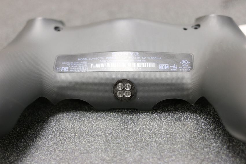
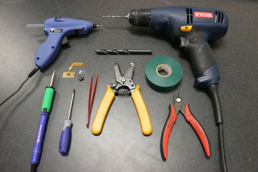
Tools needed
  •   PS4 Controller

  •   Viking PS4 Ragnarok Flex modchip DIY Kit (includes mod chip, LED board, and LED
      lense)

  •   Two diodes (included with “revision 1” LED board)

  •   Soldering iron and solder

  •   30 AWG wire (American wire gauge) or similar

  •   Wire strippers (capable of stripping above wire)

  •   Electrical tape

  •   Fine phillips screwdriver

  •   Power drill

  •   9mm and 9/64 inch drill bits

  •   Hot glue and glue gun

  •   Safety glasses

  •   Additional useful items: flux, tweezers, scissors, wire snippers, etc.

www.Extreme-Mods.com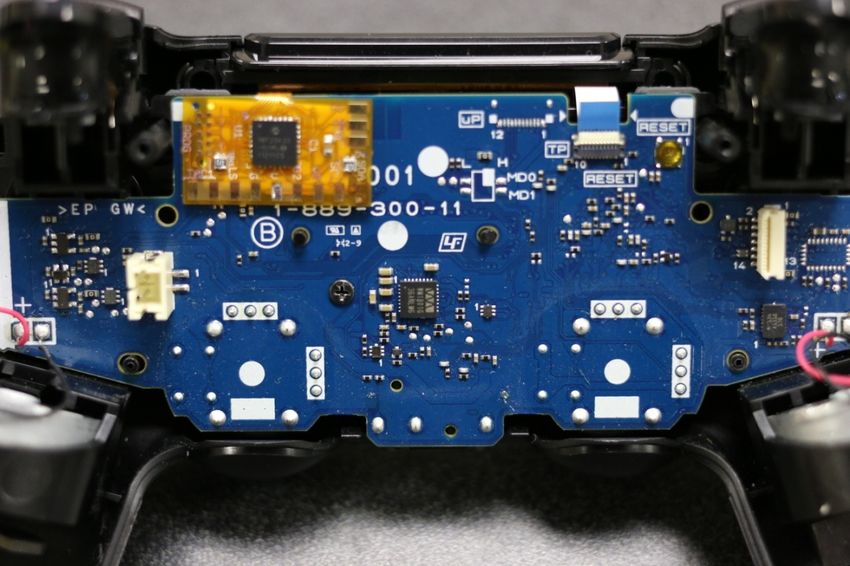
!

!
Remove the screws and cover

            !

www.Extreme-Mods.com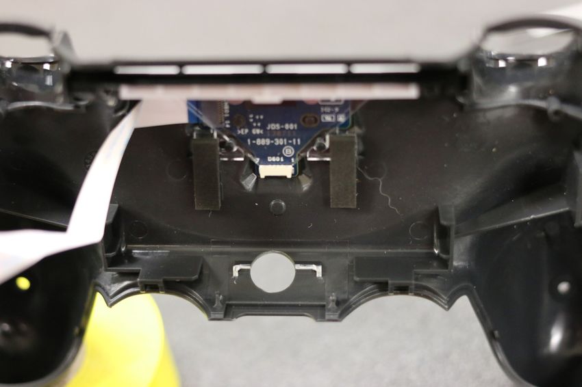
Once the 4 screws are removed, start separating the cover near the microphone port at the
bottom. It may take some force to separate the shell. Cracking noise may be heard and
some small tabs may be broken in the process, practice will make this process go more
smoothly:

               !

!

www.Extreme-Mods.com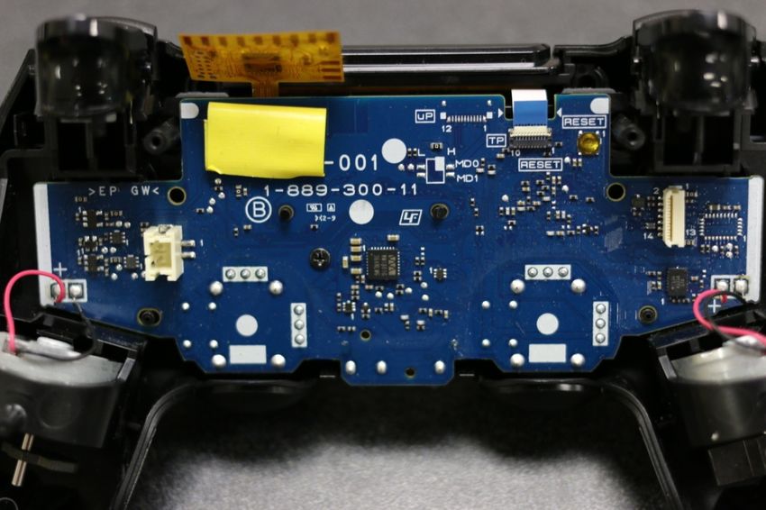
!
It is possible to remove the shell without removing either the triggers or the bumpers. The
rear part near the round end of the handles should be lifted up and over the pegs that lie
underneath:

              !

                                               !
Once the rear handles have cleared the pegs, it is possible to push the back half of the shell
“forward” to clear the bumper and triggers, without causing the triggers to pop off. Practice
will make this process go more smoothly. If the triggers pop off, LOOK AROUND CAREFULLY
FOR THE SMALL TRIGGER SPRING. The small trigger spring is required otherwise the trigger
will not return fully to the non-pressed position.

              !

www.Extreme-Mods.com
!
                                               !
Disassemble the circuit board
Once you’ve gotten the back half separated from the front half, flip it open like a clam shell:

           !

Remove the small rubber reset button as it is easy to lose. Unhook the battery wires from the
battery wires hook and remove the battery.

               !

www.Extreme-Mods.com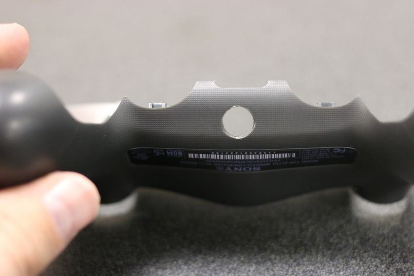
The black battery holder is held in place by two plastic tabs that “hook” around the circuit
board. The tabs can be loosened by inserting a flat-tip screwdriver in the locations shown:

       !

                                               !

           !

www.Extreme-Mods.com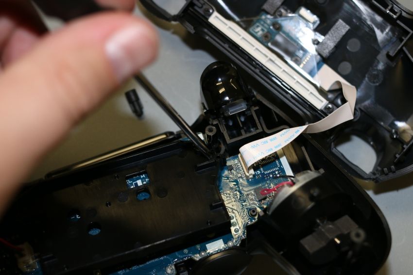
Remove the black plastic battery holder. Remove the single screw that holds the circuit board
in place. Now, remove the battery wires, remove the larger white ribbon cable by pulling
straight up on the blue tab.

Next, notice the smaller ribbon cable near the “RESET” on the board. Flip up the little white
tab, then pull the ribbon cable out by pulling on the blue tab. The white tab locks the blue
tab in place, so the white tab must be lifted before the blue tab can be pulled out.

           !

           !
                                              !
Once both ribbons have been removed, the battery has been removed, the reset button has
been removed, and the single screw has been removed, the circuit board is still permanently

www.Extreme-Mods.com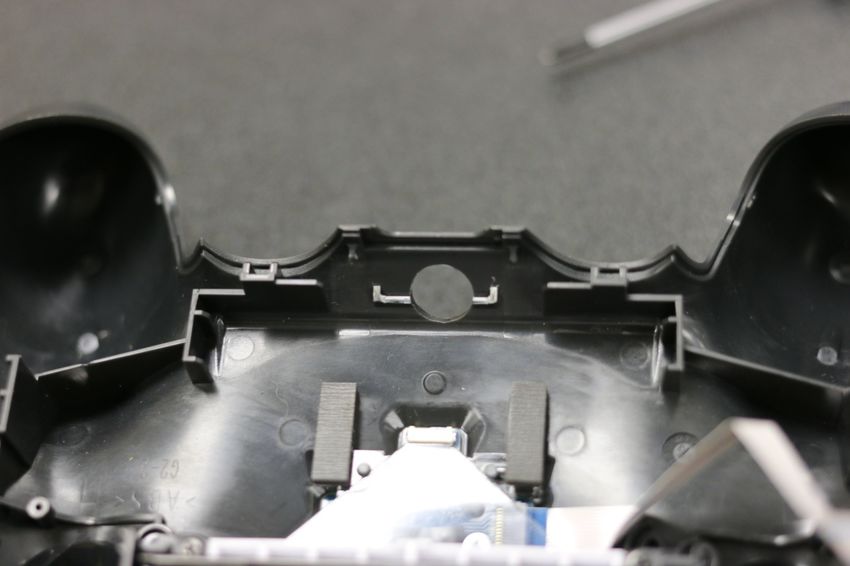
connected to the two rumble motors. Pull the circuit board up and flip it over clam-style
again:

              !

We are now ready to proceed with modchip installation.

                                              !
!

www.Extreme-Mods.com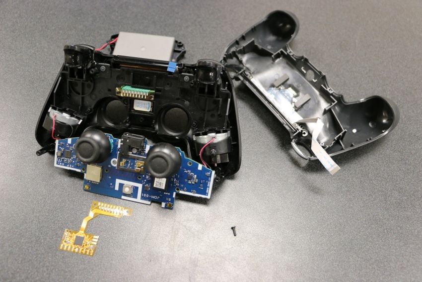
!
Install the modchip
The modchip is installed into this location:

           !

       !

www.Extreme-Mods.com
Once the solderless portion of the modchip is in place, re-install the Sony circuit board. Then
put a square of electrical tape on the Sony circuit board, and fold the modchip over and stick
it to the electrical tape:
!

!

www.Extreme-Mods.comDrill Shell and Install Indicator Drill a 9mm hole in the shell. Practice will be required to find the best location for the hole. Also drill a smaller hole as desired for the mod switch. We recommend using a smaller drill bit to drill a guide hole, then use a larger drill bit to make the hole a little larger, and then very last use the 9mm drill bit to make the hole the correct size. The LED indicator is 9mm in diameter, and by using a 9mm drill bit, the indicator makes a nice press-fit into the hole. If you attempt to drill the shell without drilling a guide hole, you will most likely end up damaging the shell as the plastic is very soft. Remove the tab of plastic before drilling: ! www.Extreme-Mods.com
!

!

www.Extreme-Mods.com
! ! www.Extreme-Mods.com
Press the LED lense all the way into the hole, noting the orientation of the two small nipples.
The nipples will line up with the notches on the LED board. The LED board should be pressed
firmly into the LED lense such that the little LED’s on the board are sitting inside the LED
lense. This will ensure best light performance.

     !

Be sure to keep the LED board tight and firm against the LED lense and aligned in the
alignment nipples, then use a few dabs of hot glue to secure everything in place.

!

One possible location for the mod switch is shown in the photo below:

www.Extreme-Mods.com
! ! ! ! ! ! ! Begin soldering the modchip www.Extreme-Mods.com
Four wires are soldered from the modchip to the Sony circuit board. “LS” which is the left
thumbstick center button, “G” which is ground, “V” which is voltage/power, and “RS” which
is the right thumbstick center button:

!

!
!
!
!
!
!
!
!
Create two small wiring harnesses: one for the mod switch (2 wires), and one for the LED
indicator (4 wires). In the photo below we have twisted 30 AWG wires together:

www.Extreme-Mods.com
!

Install the two wires for the mod switch to both legs of the mod switch. Install the four wires
for the LED board to the four pads on the LED board. The connection pairs from the modchip
to the LED board are:

www.Extreme-Mods.com
•   G2 goes to G

    •   V2 goes to V

    •   SCL goes to CL

    •   SDA goes to DA

!

Please note, if you have an early version of LED board, you will need to install the two diodes
“in series”. Both diodes can be installed together near the flex board, or you could locate
one diode on the LED board as shown above. The black band on the diode should go
“towards” the LED board and “away” from the main flex modchip. These diodes limit the
voltage and current to the LED’s.

                                    !

!
Put the controller together

www.Extreme-Mods.com
Once the 10 wires have been installed, re-install the plastic battery cover, the ribbon cables, and the rubber reset button. The wiring harnesses you created will be routed underneath the black plastic battery holder: ! Route the wiring harnesses “left” and “right” into the more open areas such that they will not get pinched or caught when the shell is closed. The LED board harness can follow the ribbon cable: ! Test the Controller The PS4 controller can be connected to a Windows PC. www.Extreme-Mods.com
!

On Windows 7 for example, connect your controller by USB to your computer, and then type
“Set up USB game controllers” into the search bar to launch the Windows native game
controller tool.

                !

!
!
!
The tool can be used to check that all button presses are functioning properly. Mods such as
rapidfire can be tested without the need for a console by monitoring the flashing lights in the
tool:

www.Extreme-Mods.com
! Once all button presses have been confirmed working and mods have been tested, it’s time to play! ! ! ! Factory Lock/Unlock Programming The mod shop must decide which mods will be unlocked for the customer. When the mod chip is powered up for the first time, it enters a special factory programming mode. The mod chips begins by asking if basic rapidfire should be unlocked. LED1 will display a color that corresponds with the various mods that can be locked or unlocked. The lock/unlock information is programmed one-by-one with the following sequence: www.Extreme-Mods.com
Color Sequence        Mod
 RED                   Rapid fire
 PURPLE                Dual-trigger Rapid Fire
 YELLOW                Jitter
 BLUE                  Akimbo Rapidfire
 GREEN                 Burst Rapidfire
                       Hybrid Optic Rapidfire (currently
 PINK                  unavailable)
 ORANGE                Dropshot/Jumpshot
 BLUE                  Fast Reload
 RED                   Quick Scope
 GREEN                 Sniper Breath Hold
 WHITE                 Zombie auto aim
 YELLOW                Auto Spot
 AQUA/LIGHT BLUE       Auto Sprint
 PINK                  Turbo Melee
 WHITE                 Selectable Button Layouts

        !
To unlock a mod, press the TRIANGLE button. LED4 will flash green to indicate that it
accepted your input and unlocked the mod. To lock a mod, press the EX button. LED4 will
flash red to indicated that it accepted your input and locked the mod.

If at any time you realize you have entered an incorrect lock/unlock, you may press the mod
switch to start over again at the beginning. Once the final mod on the list has been locked/
unlocked, the changes become permanent and cannot be changed.

www.Extreme-Mods.com
You can also read