PUSH-BUTTON / FLAME SENSING FIRE PIT INSERT - FPPK Series Installation & Operation Instructions - The Magic Of Fire
←
→
Page content transcription
If your browser does not render page correctly, please read the page content below
PUSH-BUTTON / FLAME SENSING
      FIRE PIT INSERT

                       Penta 25FPPK

                                             FPPK42X14-H

             FPPK Series
     Installation & Operation Instructions

             Hearth Products Controls

             Fire-inspired since 1975.
                     830-FPPK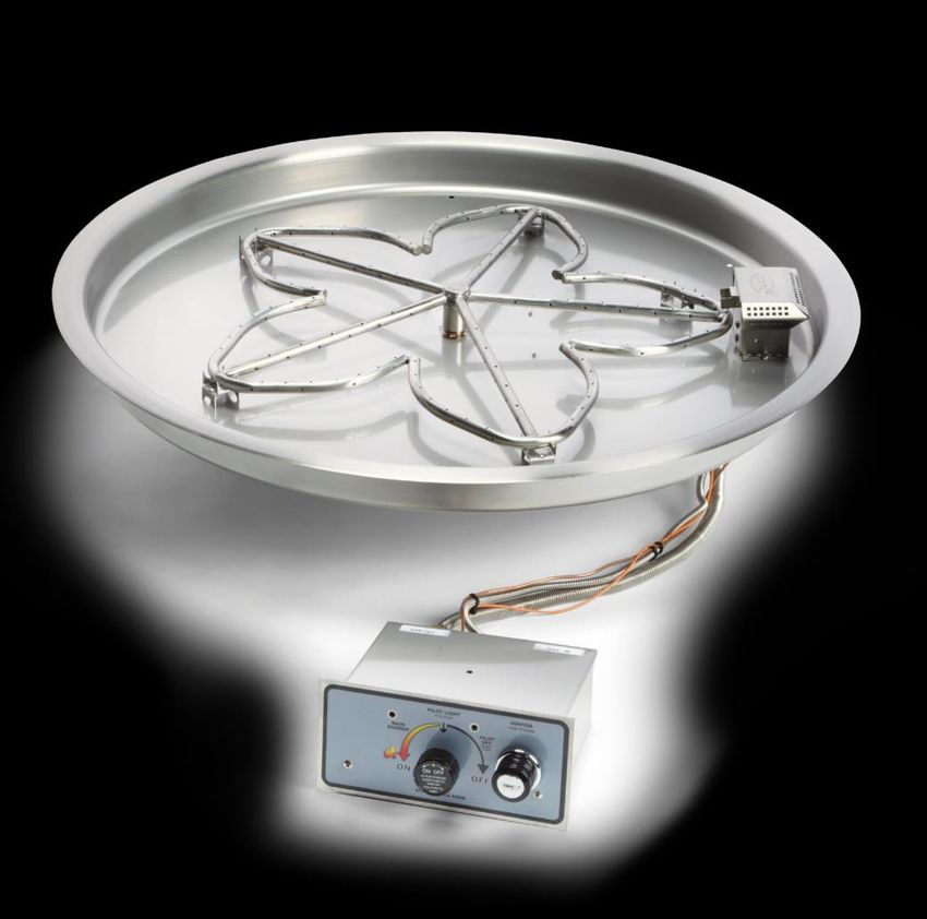
This is a Safety Alert Symbol
                          When you see this symbol on the fire pit insert, or in this manual,
                          look for one of the following signal word panels alerting you to
                          the potential for personal injury, death or major property damage.

IMPORTANT                 Necessary instructions

         WARNING
         FOR OUTDOOR USE ONLY

         WARNING
         Improper installation, adjustment, alteration, service, or maintenance can cause
         injury or property damage. Read the installation, operating, and maintenance
         instructions thoroughly before installing or servicing this equipment.

         WARNING
         • Do not store or use gasoline or other flammable vapors and liquids in vicinity
           of this or any other appliance.
         • An LP-cylinder not connected for use shall not be stored in the vicinity of this
           or any other appliance.

         DANGER
         If you smell gas:
            1) Shut off gas to appliance.
            2) Extinguish any open flame.
            3) If odor continues, keep away from appliance and immediately call
               gas supplier or fire department.

         DANGER
                      CARBON MONOXIDE HAZARD
                      This appliance can produce carbon monoxide which has no odor.
                      Using it in an enclosed space can kill you.
                      Never use this appliance in an enclosed space such as a camper,
                      tent, car or home.

The content of this manual may be revised without prior notice. Please consult with
your Hearth Products Controls representative to obtain the most current version.

C         US

                                    Hearth Products Controls                                    1
Table of Contents

1 Important Safety Information ................................................................................................. 3
  Technical Support ..................................................................................................................... 3
  Symbol Legend ......................................................................................................................... 4
  Important Safety Information for Installers ............................................................................... 5
  Important Safety Information for End-Users............................................................................. 5

2 Product Features and Parts List ..............................................................................................6

3 Selecting the Fire Pit Location.................................................................................................7

4 Overhead Structures and Sidewall Clearance Requirements ................................................ 8

5 Fire Pit Enclosures Requirements ................................................................................................... 10

6 Remote LP Tank System Enclosure Requirements - If Applicable ...................................... 12

7 Installing the Fire Pit............................................................................................................. 16

8 Adding Approved Media ................................................................................................................... 17

9 Operating the Fire Pit ............................................................................................................ 19

10 Maintaining the Fire Pit ...................................................................................................... 21

11 Troubleshooting ................................................................................................................................ 23

12 Compatible Accessories ................................................................................................................. 24

13 Replacement Parts .......................................................................................................................... 24

14 Warranty ............................................................................................................................................. 25

                                                                                     Hearth Products Controls                                                  2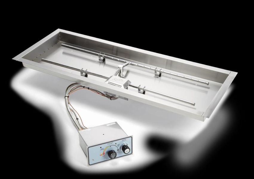
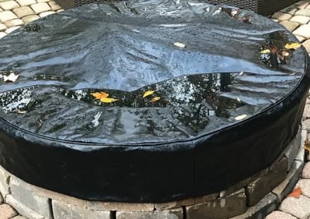
Table of Contents

• Hearth Products Controls Company recommends that our products are installed
  by professionals locally licensed by the authority having jurisdiction in gas piping.   INSTALLER:
  All installation instructions must be followed to ensure proper performance and         Leave this manual with
  safety. Hearth Products Controls Company assumes no responsibility for problems         the appliance.
  relating to the installation.                                                           END USER:
                                                                                          Retain this manual for
• To qualify for warranty, all instructions must be strictly followed. Otherwise,
                                                                                          future reference.
  warranty may be void. Never alter product or configuration in any way.

• Annual servicing should be handled by professionals certified in the US by the
  National Fireplace Institute (NFI) as NFI Gas Specialists or in Canada by WETT           SELECT MODELS
  (Wood Energy Technical Training).                                                          Certified to
                                                                                           ANSI Z21.97-2014
• It is the installer’s responsibility to ensure a safe installation and to educate the     CSA 2.41-2014
  end-user regarding the features, safety recommendations and proper operation
  of this product.

• Please reference page 1 for all warnings.                                                     C       US

Technical Support
For information and support contact your Hearth Products Controls dealer.

                                                    Hearth Products Controls                                       3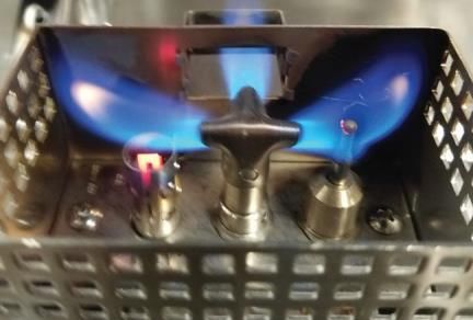
1 Important Safety Information

 Symbol Legend
                   This is a Safety Alert Symbol
                   When you see this symbol on the fire pit insert, or in this manual, look for one
                   of the following signal word panels alerting you to the potential for personal
                   injury, death or major property damage.

   IMPORTANT       Necessary instructions

                                      Hearth Products Controls                                        4
1 Important Safety Information

Please reference page 1 for all warnings.

Important Safety Information for Installers
Leave this manual with the end-user and instruct them to retain it for future
reference. Instructions and product updates are also available at www.hpcfire.com
under the Support tab.

Installers must carefully follow the instructions in this manual to prevent personal
injury or property loss. These instructions contain information critical to the safe
installation and operation of the fire pit.

• Instructions are updated as needed. It is the responsibility of the installers to
  check for product updates and installation manual updates at www.hpcfire.com/
  support.html prior to installation.

• It is the responsibility of the installer to follow:

  - The National Fuel Gas Code, ANSI Z223.1/NFPA 54 or International Fuel
    Gas Code.

  - The National Electrical Code, ANSI/NFPA 70.

  - Local codes

• Only use gas/fuel type specified for this fire pit as noted on the fire pit control
  box label. NEVER use an alternative fuel to include bio-fuel, ethanol, lighter fluid
  or any other fuel.

• Gas pressure and type should be checked prior to installation and use.

  - Natural Gas Fire Pit: Supply Pressure: Minimum: 3.5 inches W.C.;
    Maximum: 7.0 inches W.C.

  - LP Gas: Supply Pressure: Minimum: 8.0 inches W.C.;
    Maximum: 11.0 inches W.C.

Important Safety Information for End-Users
• Never leave an operating fire pit unattended or with someone not familiar with
  its operation or emergency shut-off locations.

• Both children and adults should be alerted to the hazards of high surface
  temperatures and should stay away to avoid burns and clothing ignition.

• Young children should be carefully supervised when they are in the area of fire pit.

• Keep the appliance area clear and free from combustible materials, gasoline,
  and other flammable vapors and liquids.

                                                         Hearth Products Controls        5
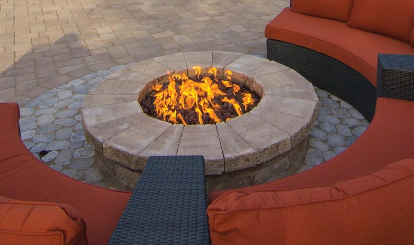
2 Product Features and Parts List

Fire Pit Insert
Installation and Operation Instructions

                                                                            Pan

                                                                                           Burner

                                                                                                Ignition System
                                                                                                Blowout Box

                                                                                                Flex line hose

             FPPK Control Box

                                 Valve control                       Push-button igniter

                                                 Hearth Products Controls                                         6
3 Selecting the Fire Pit Location

NOTE: All fire pits and systems are designed and intended for outdoor use only.

                        It is recommended that material such as granite, marble
 IMPORTANT
                        or other dense stone be kept away from heat and
                        especially flame due to risk of cracking. HPC is not
                        responsible for damage resulting from failure to follow
                        these recommendations.

• Select a location that

  - ensures above-grade installation of the fire pit.

  - offers good drainage.

  - allows easy access for installation and maintenance of the fire pit.

  - provides sufficient horizontal room to enjoy the fire pit while allowing a safe
    distance from the heat and flame.

• Fire pits create very high temperatures. For clearances refer to table 3.1.
  Clothing or other flammable materials should not be placed on or near fire pit.

Clearances around Fire Pit
 Fire Pit Clearances                                                          Up to 142K
 Under Valve Box when applicable for drainage                                     2"
                                                                             36" (12" for
 Sides Surrounding Fire Pit From Structure or Combustibles
                                                                          noncombustibles)
 Overhead Clearance above Product                                                84"

Table 3.1 – Fire Pit Clearances

                                                   Hearth Products Controls                  7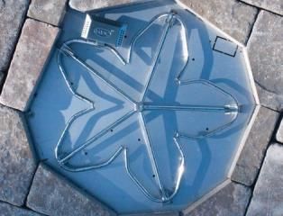
4 Overhead Structures and Sidewall Clearance Requirements

  It’s important to review the clearance requirements below for any type of overhead
  structure such as pergola, roof, overhang, screens, arbor, etc. or a sidewall to ensure
  that the distances are met. Figures 4.1 and 4.2.

                1 -–Up
                                                                                                                                              REVISIONS
        Figure
         Figure4.1   Upto
                        to142k
                           142kBTU
                               BTU                                                    ZONE          REV                      DESCRIPTION                            DATE             APPROVED
                  For
                  ForOutdoor
                      Outdoor Use Only
                                  Only

                                                                            Overhead solid structure:
                                                                            (Floor, overhang, pergola or screen)

                                                                                                                                                            Solid structure or combustible
                                                                                                                                                            on no more than 2 sides
                                                                                                                                                            of the fire pit
                                                                                                                                                              -12" minimum clearance for
                                                                                                                                                               noncombustible materials
                              Residential                                                           84"
                                   or
                              Commercial
                               Building                             36"                                                       36"
                                  on                                                                                                                           all non-combustible materials
                             no more than
                                2 sides
                                                                                                                                                               Minimum of 2 each - 18 sq/in vents
                                                                                                                                                               on opposing sides

                                                                                                                   Permanent fuel supply
                                                                                                                   plumbed by certified installer
 Combustable Material:                                                                                             and inspected by local authority
 -For direct install on decking, joist and trusses
 see Deck Installation Kit drawing and instructions

                                                                      DRAWN                  DATE
                           Diagram illustrates common
                           clearance questions.                                                 2/22/2018
                                                                                                                                    Clearances Standard
                                                                                                                                       FPPK Fire Pit Up to 142k btu
                           * Clearance from overhead structure        CHECKED
                           * Clearance from structure/combustible

                           All items may or may not apply to          QA
                           your project.                                                                                                       Hearth Products Controls
                                                                      MFG                                      SIZE      FSCM NO.                DWG NO.                                       REV
                           Clearance's apply to any and all sides
                           of the project.                                                                         A
                           Read and follow all instructions           APPROVED
                                                                                                              SCALE                                              SHEET
                           and local codes

  Table 4.1 – Clearances for standard fire pit up to 142k BTU

                                                                                 Hearth Products Controls                                                                                      8
4 Overhead Structures and Sidewall Clearance Requirements
1 -–up
REVISIONS
Figure
Figure4.2 Uptoto100,000
100,000BTU
BTU: :LP
LPTank
Tank
Only–- Select
ZONE REV DESCRIPTION DATE APPROVED
For
ForOutdoor
OutdoorUse
UseOnly Modelsonly
Select models Only
Overhead structure to include:
(roof, overhang, pergola, or screen)
for products up to 100,000 BTU.
Solid structure or combustible
on no more than 2 sides
of the fire pit
-12" minimum clearance for
noncombustible materials
Residential 84"
or
Commercial
Building 36" 36"
on
no more than Enclosure constructed of
2 sides all non-combustible materials
Minimum of 2 each - 18 sq/in vents
on opposing sides
Min
Combustable Material: 54"
-For direct install on decking, joist and trusses
see Deck Installation Kit drawing and instructions
Diagram illustrates common DRAWN DATE
clearance questions. 2/22/2018 Clearance
LP Tank -LPFire
tankPit
fireup
pit to
up 100K
to 100kBTU's
BTU
* Clearance from overhead structure CHECKED
* Clearance from structure/combustible
All items may or may not apply to QA
your project. Hearth Products Controls
MFG SIZE FSCM NO. DWG NO. REV
Clearance's apply to any and all sides
of the project. A
Read and follow all instructions APPROVED
SCALE SHEET
and local codes
Table 4.2 – Clearances for LP tank fire pit up to 100k BTU
Hearth Products Controls 95 Fire Pit Enclosures Requirements
Location and design
• The enclosure must be installed above-grade and
allow for drainage to prevent water damage to fire pit.
• Refer to cut sheets on our website for important Figure 5.1 – Pan lip recessed on a trough.
dimensional information for your fire pit.
Visit www.hpcfire.com
• The fire pit assembly should be recessed a minimum of two inches from the top
of the enclosure to protect flame from being blown out.
• It is recommended that material such as granite, marble or other dense stone be
kept away from heat and especially flame due to risk of cracking. Manufacturer
is not responsible for damage.
• The enclosure must be constructed on a stable surface and be level. HPC
recommends the use of the installation collar (optional) that may be mortared
into or sandwiched between layers of the enclosure.
• The weight of the fire pit must be supported by the pan and not by any control/
valve box.
• HPC recommends that the pan lip is recessed on a trough (linear), and large
round enclosures, Figure 5.1. NOTE: HPC cannot guarantee the lip on all of our
products will be perfectly flat and will not warp due to heat.
• There must be a minimum of 2 inches under the valve box for proper ventilation
and drainage, see clearance drawings on page 8 an 9.
• The product must be accessible for service.
Hearth Products Controls 105 Fire Pit Enclosures Requirements
Construction materials
• Use non-combustible materials and construction for gas supply, power
and enclosure.
• The interior void space of the enclosure surrounding the valve box
cannot be filled with any material (gravel, crushed rock, concrete, etc.).
Venting
• The enclosure must incorporate at least two vents to allow heat and or
residual fuel to escape. Failure to properly vent the enclosure may result in
the fire pit overheating or explosion.
• Some enclosures may require more ventilation based on material, size, and
extended use.
• The vent may also work as a drain when installed at bottom sidewall to
prevent water build up.
• Vent specifications:
- A minimum of two vents (18 square inches for each vent) on opposing
sides of the enclosure totaling 36 inches of free area are required
(example: 3-inch x 6-inch or larger). Or, multiple vents uniformly made
throughout the enclosure totaling 36 square inches or more of free area
are acceptable.
- Installation of the vents in the mid-to-lower area of the enclosure is
recommended.
Fuel line
• Fire pit must have a gas shutoff on the outside of the exterior of the fire pit to
allow for emergency shut off and maintenance. The gas shutoff should not
be used to adjust flame height.
• The installer is responsible for using the correct fuel line sizing that is able to
supply the stated maximum BTU for the product—refer to product label on
the fire pit for specifications.
Hearth Products Controls 116 Remote LP Tank System Enclosure Requirements - If Applicable
Only select models of Push-Button / Match-Lit
IMPORTANT
(FPPK and MLFPK) fire pits are permissible for small
tank use. Please see the HPC product catalog, visit
www.hpcfire.com, or contact your HPC dealer for details.
Locate the hose out of pathways to avoid accidental
IMPORTANT
damage and prevent it from becoming a trip hazard.
For an enclosure using an LP tank system, follow these recommended
specifications:
• You must follow local codes.
The remote LP tank / enclosure should be a
IMPORTANT
minimum of 54 inches from the fire pit.
• One side of the enclosure shall be completely open; OR
• For an enclosure having four sides, a top, and a
bottom:
- At least two ventilation openings shall be provided
in the side walls of the enclosure, located within 5
inches (127mm) of the top of the enclosure, equally
sized, spaced at a minimum of 180 degrees, and
unobstructed. The opening(s) shall have a total free
area of not less than 1 in2 lb (14.2 cm2kg) of stored
fuel capacity. See Figure 6.1.
- Ventilation opening(s) shall be provided at the floor
level of the enclosure and shall have a total free area
of not less than 1/2 in2 lb (7.1 cm2kg) of stored fuel
capacity. If ventilation openings at floor level are in a
side wall, there shall be at least two openings. The
bottom of the openings shall be 1 inch (25.4mm) or
less from the floor level and the upper edge no more
than 5 inches (127mm) above the floor level. The
openings shall be equally sized, spaced at a minimum
of 180 degrees and unobstructed. See Figure 6 1.
Figure 6.1 – Top and bottom side ventilation openings
• Every opening shall have minimum dimensions so as to for LP tank enclosure.
permit the entrance of an 1/8 inch (3.2mm) diameter rod.
Hearth Products Controls 126 Remote LP Tank System Enclosure Requirements - If Applicable
• Ventilation openings in sidewalls shall not communicate directly with other
enclosures of the appliance. See Tables 6.1 and 6.2.
LP Tank Size Top Opening Bottom Opening
20 LB (9.1 KG) 20 in2 (130 cm2) 10 in2 (65 cm2)
30 LB (13.6 KG) 30 in2 (195 cm2) 15 in2 (100 cm2)
Table 6.1 – LP tank enclosure opening specifications by tank size.
LP Tank Enclosure Specifications
2 Openings for each top and bottom - 180° apart
From LP tank base to bottom of opening - Max. 1" (25.4mm)
From floor to base of LP tank - Min. 2" (50.8mm)
Table 6.2 – LP tank enclosure opening specifications.
• The cylinder valve shall be readily accessible for hand operation. A door on the
enclosure to gain access to the cylinder valves is acceptable, provided it is non-
locking and can be opened without the use of tools. Designs using a cover to gain
access to the cylinder and cylinder valve shall be provided with handles or the
equivalent at a minimum of 180 degrees apart to facilitate lifting of the cover.
• The enclosure for the LP-gas cylinder shall isolate the cylinder from the burner
compartment to provide:
- Shielding from radiation;
- A flame barrier; and
- Protection from foreign material.
• There shall be a minimum clearance of 2 inches (50.8mm) between the floor of the
non-disposable LP-gas cylinder enclosure and the ground.
• The design of the enclosure shall be such that:
- A non-disposable LP-gas cylinder can be connected, disconnected, and the
connections inspected and tested outside the cylinder enclosure; and
- Those connections, which could be disturbed when installing the cylinder in the
enclosure, can be leak-tested inside the enclosure.
Hearth Products Controls 136 Remote LP Tank System Enclosure Requirements - If Applicable
Propane Cylinder: Safety Requirements
• This appliance has been designed for use with a 20-lb. or 30-lb. size propane
cylinder (not supplied).
• The propane cylinder should be checked by your propane supplier prior to
installation and use.
• Never use a cylinder with a damaged valve. A worn cylinder may be hazardous and
should be checked by your propane supplier.
• Use only a propane supply cylinder constructed and marked in accordance with the
specifications for LP gas cylinders by the National Standard of Canada, CAN/CSA
B339, Cylinders, Spheres and Tubes for Transportation of Dangerous Goods; and
Commission, as applicable or the Specifications for LP-Gas Cylinders of by the U.S.
Department of Transportation (DOT).
• Do not store a spare LP-gas cylinder under or near this appliance.
• Never fill the cylinder beyond 80 percent full.
• Only use the pressure regulator and hose assembly provided with this appliance
or replacement pressure regulators and hose assemblies as specified by the
manufacturer. The regulator supplies a pressure of 11 inches water column to the
appliance and has a QCC1 type fitting.
Propane cylinder specifications
• The propane cylinder must be provided with a cylinder connection device
compatible with the connection for outdoor appliances.
• The propane cylinder must be supplied with a shut-off valve terminating in a propane
cylinder valve type QCC1 and include a collar to protect the cylinder valve. A QCC1
cylinder has a positive seating connection, which will not allow gas to flow until a
positive seal has been achieved. It is also equipped with an excess flow device. In
order to attain full flow to the appliance, the valve must be in the off position when
the cylinder valve is turned on.
• The propane cylinder must have a safety relief device having direct communication
with the vapor space of the cylinder.
• The cylinder supply system must be arranged for vapor withdrawal.
• The cylinder shall incorporate listed overfill protection device (OPD).
Hearth Products Controls 146 Remote LP Tank System Enclosure Requirements – If Applicable
Locating the LP tank:
Figure 6.2
Securing the LP tank:
WARNING
1. Fasten the L-bracket to the bottom of the propane
tank using the nut and bolt (supplied). Ensure the nut Failure to follow location and mounting guidelines
is tight and will not loosen. for the LP tank could result in serious injury.
2. Select the location for the propane tank following the
guidelines above, Figure 6.2.
WARNING
3. Screw the bracket to the mounting surface. For
concrete surface, use a concrete anchor (not • Locate the LP Tank and enclosure out of pathways
to avoid accidental damage and prevent them
supplied). Ensure that screw is tight so that the from becoming a trip hazard.
cylinder cannot move.
• Locate the hose out of pathways to avoid
accidental damage and prevent it from becoming
a trip hazard.
Connecting the Cylinder:
1. Ensure the gas regulator has no kinks and is
smooth. WARNING
2. Remove the cap or plug from the cylinder fuel valve.
• Always ensure L-bracket is securely fastened to
3. Insert the black QCC1 regulator nipple onto the prevent the LP tank from tipping.
QCC1 fuel valve and tighten until snug. Do not use
tools.
INSTALLATION
4. Perform a leak test on all joints prior to using the gas
appliance. A leak test must be performed annually We suggest that our products be installed by
and each time a cylinder is hooked up or if a part of professionals that are locally licensed by the
the gas system is replaced. authority having jurisdiction in gas piping.
5. Follow the instructions for natural gas hook-up if
the appliance is to be connected directly to a house
propane gas supply line.
Hearth Products Controls 157 Installing the Fire Pit
INSTALLATION
We suggest that our products be installed by professionals that are locally
licensed by the authority having jurisdiction in gas piping.
To prevent damage, unhook the fire pit from the gas
IMPORTANT
supply for pressure leak tests.
Burn Testing: It is the responsibility of the qualified
IMPORTANT
installer to test for gas leaks at all connections.
Gas Plumbing Connections: Use joint compound or tape
IMPORTANT
that is resistant to all gases. Apply joint compound only to
all male pipe fittings. DO NOT use on flex line flared
fittings. Be sure to tighten every joint securely.
• Perform all leak tests with leak detector or leak reactant.
Installation Steps:
1. Set fire pit in properly constructed enclosure, read 8. Turn off fire pit and allow it to cool.
Section 5 – Fire Pit Enclosure Requirements.
9. Apply media as described in Section 8, Adding
2. Position fire pit following safety recommendations Approved Media. When filling the pan with lava
with access to all gas connections for testing. rock and/or decorative glass, the instructions in
Read Section 3 – Selecting the Fire Pit Location Section 8 must be followed.
for more details.
10. Turn on fire pit again and perform leak test with
3. Shut off gas supply to fire pit. media correctly installed. If gas leak is detected verify
correct media application and repair as needed.
4. Connect fire pit to main gas supply. Warning:
avoid sharp bends with flex line to prevent whistling. 11. Verify correct operation and lighting.
5. Turn on gas supply, purge gas lines of air and 12. Review safety manual with end-user. Instruct end-
perform leak test on all inlet connections. user that fire pit or media must not be changed or
Repair as needed. modified.
6. Light fire pit. It may take several cycles to purge 13. Leave manual with end user.
air from the lines. Read Section 9 – Operating the
14. Apply the Start Up and Shutdown decal next to
Fire Pit.
control box in an obvious and highly visible position.
7. Once fire pit is lit, perform leak test on all gas
connections. Repair as needed.
For Penta Burner inserts, flame
IMPORTANT
will be smaller with no media
on the burner.
Hearth Products Controls 168 Adding Approved Media
WARNING
FOR GLASS MEDIA USAGE WITH LP GAS- WHEN USING APPROVED
DECORATIVE GLASS TO COVER BURNER APPLY ONLY ENOUGH TO HIDE
BURNER. APPLYING OVER 1/2” MAY CREATE BACK PRESSURE AND GAS
LEAKAGE FROM AIR MIXER RESULTING IN LP POOLING UNDER FIRE PIT.
WARNING
FOR GLASS MEDIA USAGE WITH LP GAS- THE UNIT MUST BE TESTED WITH
MEDIA OVER BURNER FOR CONFIRMATION OF NO BACK PRESSURE CREATING
GAS TO LEAK OUT OF AIR MIXER VENTURI HOLES. THIS MAY HAVE TO BE
DONE PRIOR TO PLACING IN ENCLOSURE IF NO ACCESS DOOR.
WARNING
Never use any material that is non-porous or holds moisture such as gravel,
pebbles, river rock, etc. When heated, non-porous material will not allow heated
steam to readily escape which can break and cause personal injury or damage.
Material that holds moisture can boil and fracture unexpectedly when exposed
to heat.
• IMPORTANT The fire pit is designed to use approved media correctly
installed over the burner to achieve proper combustion.
• Never install a mesh or screen under the media.
• Media affects flame pattern greatly. It is possible to create an unusual flame pattern
that could damage your enclosure. Enclosure damage from an open flame fire
feature is not covered under any warranty.
• The use of concrete logs is not recommended.
Hearth Products Controls 178 Adding Approved Media
Application of Approved Media
Please follow the instructions below to add the finishing touch to your fire pit.
Particular attention needs to be on the pilot assembly area.
Incorrect media installation will cause the pilot flame to suffocate and turn off pit
or delay main burner ignition.
Lava Rock Only Application Decorative Glass Application
1) Install your fire pit per instructions. 1) Install your fire pit per instructions.
2) Apply lava rock ONLY deep enough to cover ring. 2) Fill pan with media. Cover burner with 1/4 to 1/2
inches of glass. Do not overfill pan with glass.
All LP installations must be checked for back
pressure with media installed. Failure to do so may
result in personal injury or property damage.
1) Blowout Box: Leave vents open. Do not cover
vents with lava rock or allow any rock to block
flame opening. Incorrect media installation will
cause the pilot flame to suffocate and turn off pit
or delay main burner ignition. 3) Blowout Box: Do not cover blowout box vents or
2) opening with glass. Incorrect media installation will
cause the pilot flame to suffocate and turn off pit
or delay main burner ignition.
Do not cover box vents!
Do not cover box vents! Do not cover pilot opening!
Hearth Products Controls 189 Operating the Fire Pit
• Before use, be sure to test all gas connections for leaks. Do not use fire pit if there is
any evidence of leaking gas. If leaking gas suspected, turn off the main gas supply
and repair immediately.
• Do not use the enclosure as a seating area. Wind and gusty conditions will affect the
flame in an unpredictable manner. If conditions exist that are not safe for patrons,
turn off the fire pit.
• The hose should be inspected before each use of the fire pit and replaced prior to
use if there is evidence of excessive abrasion or wear or if the hose is damaged.
The replacement hose assembly shall be that specified by the manufacturer.
• Do not use the fire pit if any part has been under water. Immediately call a qualified
service technician to inspect the fire pit and to replace any part of the control system
and any gas control that has been under water.
• Never use any material that is non-porous and holds moisture such as gravel,
pebbles, river rock, etc. This material, when heated will cause the trapped moisture
to boil and fracture unexpectedly. This material is not sufficiently porous to allow
heated steam to readily escape which can break and cause personal injury or
damage.
• Solid fuels shall not be burned in the fire pit.
• Leaves, sticks, wood, paper, clothing, food material, should be kept away from the
fire pit. Clothing or other flammable materials should not be hung from the appliance
or placed on or near the appliance. Keep the appliance area free from gasoline, and
other flammable vapors and liquids.
• Fire pit is not for cooking.
• Make sure that there is no vegetation or other objects over the top or sides of
the fire pit that could interfere with safe operation. See clearances in Section 3 –
Selecting the Fire Pit Location.
• If lava rock is wet, allow the fire pit to burn for 45 minutes prior to coming within
15 feet of the fire pit.
• When the fire pit is not in operation, turn off gas valve.
• When not in use, the fire pit must be covered at all times.
Hearth Products Controls 199 Operating the Fire Pit
FPPK Push-Button Flame Sensing DANGER
Start-up If you smell gas:
1. STOP! Read the safety information on 1) Shut off gas to appliance.
“If you smell gas”, Section 1 – Important 2) Extinguish any open flame.
Safety Information. 3) If odor continues, keep away from
appliance and immediately call
2. Ensure fire pit is clear of people and debris. gas supplier or fire department.
Remove any covers and the fire pit is safe to
start.
3. Turn gas supply valve to fire pit to ON position FPPK Shutdown
4. Rotate gas valve knob counter clockwise to pilot 1. Turn “off” fire pit
light position by slightly pressing
5. Depress and hold the valve knob. and turning valve
clockwise to “OFF”
6. Turn ON spark igniter by depressing switch in position, Figure 9.1.
short burst until pilot lights. Figure 9.1
2 Slightly push in and
7. Once lit, release switch for spark igniter turn clockwise to
while continuing to depress valve knob for extinguish pilot,
20 seconds. Figure 9.2.
8. Turn knob counter clockwise to light main 3. Turn off main gas
burner. valve to fire pit.
Figure 9.2
NOTE: If the burner fails to light, wait 5 minutes for 4. After fire pit has
gas to clear, then repeat steps 3-8. cooled, cover fire pit.
9. Ensure fire pit, children and patrons are
supervised by a responsible adult who is familiar
with emergency shut-down.
10. Flammable materials should not be placed on or
near the fire pit.
This product is intended to be connected
to fixed piping systems or an LP small tank
(only on select models).
Hearth Products Controls 2010 Maintaining the Fire Pit
• Any guard or protective device removed for servicing must
be replaced prior to operating the fire pit. Service
• We suggest that our products be serviced annually by a We suggest that our products
professional certified in the US by the National Fireplace be serviced by a professional
Institute (NFI) as NFI Gas Specialists. certified in the US by the
National Fireplace Institute
• Ensure gas is shut off and fire pit is cool before servicing. (NFI) as NFI Gas Specialists.
• Keep fire pit covered at all times when not in use and free
of debris.
• In some areas of the country, spiders or insects have been known to build
nests and/or lay eggs in the venturi holes of the air-mixer for LP units.
This can cause fuel to fill the fire feature cavity and result in personal injury
or property damage. Periodic inspection by a qualified service technician
of the air-mixer is required to ensure your fire feature performs properly,
Figure 10.1.
• Burner Cleaning: One time a year. If flames exhibit any abnormal
shapes or behavior, or if burner fails to ignite properly, then the burner
holes may require cleaning. The appliance can be cleaned by carefully Figure 10.1 – Locating orifice for
cleaning
removing the logs and media to allow access to burner. Use a brush to
carefully remove dust, spider webs, and loose particles from base, logs,
and fire ring itself. If evidence of damage, fire ring must be replaced with
fire ring specified by the manufacturer.
• Thermocouple cleaning of soot: Once every six months or as
needed. Remove lava rock & glass around pilot, then the blowout box
lid. Clean thermocouple of any soot using soft brush. Be careful not to
damage hot wire element. Place lava rock or glass back as explained in
Section 8 – Adding Approved Media.
Figure 10.2 – Pilot flame coverage of
• Visually inspect the pilot. The pilot flame should cover 3/8 inch to thermocouple.
1/2 inch of the thermocouple, Figure 10.2. Cleaning of the pilot orifice may
be required by removing pilot hood counter clockwise and removing orifice,
Figure 10.3.
Figure 10.3 – Cleaning pilot orifice
Hearth Products Controls 2110 Maintaining the Fire Pit
Installing / Changing Batteries to Spark Igniter Unit in Valve Box
Carefully unscrew the spark igniter unit cap, Figure 10.4.
1. Remove cap with battery, Figure 10.5.
2. Remove old battery from cap, install new battery
3. Holding by cap, slide battery into spark igniter unit, Figure 10.6 .
4. Tighten cap lightly- DO NOT over tighten. Figure 10.4 – Unscrew spark igniter
unit cap.
We recommend using Alkaline battery.
Figure 10.5 – Remove igniter unit cap
with battery.
Battery
Figure 10.6 – Slide battery into spark
igniter unit.
Hearth Products Controls 2211 Troubleshooting
Table 11.1, below indicates some potential causes
and countermeasures to the symptoms indicated in Service
bold type. Please contact your retailer or certified We suggest that our products be
technician for service and repair. serviced by a professional certified in
the US by the National Fireplace
Institute (NFI) as NFI Gas Specialists.
Problem Possible Causes Solution
New install - may take several attempts
Air in gas line
Check gas level of LP tank
Pilot Will Not Light Confirm gas is ON upstream
No gas flow - gas not ON or line obstruction
Possible debris in line: insulation, dirt, plastic, etc.
Pilot orifice dirty or clogged Remove orifice and clean (Section 10)
Dead or incorrectly installed battery Replace properly with good AA battery (Section 10)
Pilot will not light with
The gap can be adjusted by bending the tip in or
spark igniter but will
Improper gap at electrode tip out while holding electrode stable above ceramic
light with a match
block to achieve spark
Thermocouple must have time to heat up. Hold the
Knob not being held in long enough
Pilot will not stay lit knob in for 30 seconds after pilot lights.
when control knob Small pilot flame: pilot orifice dirty or clogged Remove pilot orifice and clean
released Dirty thermocouple Clean using soft brush (Section 10)
Faulty thermocouple or valve Replace thermocouple or valve
Confirm proper gas pressure (See Section 1 –
Gas pressure improper
Important Information for Installers)
Burner obstructed Confirm no water or debris in burner
Burner will not stay lit
Improperly applied or too much media Re-apply media (Section 8)
Use when less windy or with our wind guard
Too windy
(See page 24, Figure 12.1)
Confirm proper gas pressure (See Section 1 –
Gas pressure improper
Important Information for Installers)
Fire pit valve must be OFF when tank is turned ON.
Propane (LP) - Improper lighting procedure
Low flame when Turn ON tank slowly to allow pressure to equalize
turned to High Lack of gas Check gas level of LP tank
Supply hose is pinched Reposition supply hose as necessary
Gas pipe, flex line, shutoff valve, etc. must be sized
Natural Gas (NG) - undersized gas supply line
to deliver fire pit input pressure & BTU requirement
Flame is creating Propane (LP) - mesh spider guard or venturis
Thoroughly clean spider guard - (Section 10)
large amount of soot are blocked with debris - grass, dirt, etc.
Whistling - flex line bent too sharp Re-route flex line to reduce bend
Noise when lit Not a defect - normal occurrence on hot days due
Propane (LP) - Humming regulator
to internal vibrations in regulator
Table 11.1 – Troubleshooting
Hearth Products Controls 2312 Compatible Accessories
• Wind guards – Clear glass wind guards protect flames from being
blown out in windy conditions as well as personal belongings from
being blown into the fire. Available in round, linear and square
shapes. See Figure 12.1.
• Fire pit cover – Hearth Products Controls has decorative copper
covers and heavy-duty vinyl covers for your fire pit that will protect
it from rain, snow, and moisture. See Figure 12.2.
For a complete list of accessories, visit www.hpcfire.com Figure 12.1 – Wind guard
Figure 12.2 – Fire pit cover
13 Replacement Parts
Please contact your dealer for parts – if unsure please contact HPC or visit
our website at www.hpcfire.com and we will be happy to help you
Hearth Products Controls 2414 Warranty
Limited Warranty
Hearth Products Controls Company (HPC) warranties fire pits against manufacturing defects that prevent safe
and correct function as follows:
• Electronics, Gas valve: Commercial-1 yr; Residential- 3 yr.
• Pilot Assembly: Commercial- 1 yr; Residential- 2 yr.
• Stainless Steel Pan, Fire Ring, & Valve Box: Commercial-1 yr.; Residential-5 yrs.
This commences from the date of original sale / shipment from HPC FOB Dayton, Ohio. This warranty is for
parts and in-house (HPC) labor. The defective product must be sent back to HPC with a Return Merchandise
Authorization (RMA) issued by HPC for that specific product and any other additional information for the nature
of the defect or warranty claim.
The warranty does not cover items that have been damaged by overheating, modification, abuse, or improper
storage. Also any labor involving installation or maintenance with the unit is not covered.
This warranty excludes claims for consequential, indirect-collateral expenses arising from product defects or
warranty recovery.
Hearth Products Controls
Fire-inspired since 1975.
3050 Plainfield Road
Kettering, Ohio 45432
For detailed product information, go to www.hpcfire.com
©2018 Hearth Products Controls 5/21 830-FPPKYou can also read