Rail technical background - November 2020 - GOV.WALES
←
→
Page content transcription
If your browser does not render page correctly, please read the page content below
Rail technical background
November 2020
Contents
1.     Introduction                                                                       1

2.     Existing Infrastructure                                                            3

3.     Further Impacts Outside of SWML Operational Scope                                 20

4.     Newport West Station                                                              24

5.     Somerton Station (Newport East)                                                   37

6.     Impacts on Other SWML Station Proposals                                           43

7.     Existing SWML Stations                                                            46

© Hawlfraint y Goron / Crown copyright 2020   WG41572   Digital ISBN 978-1-80082-486-7
1 Rail technical background
1. Introduction
1.1 This report provides technical background on the rail measures considered by the
South East Wales Transport Commission (SEWTC). It provides an overview of the
different areas considered and more detail on how they have been determined.
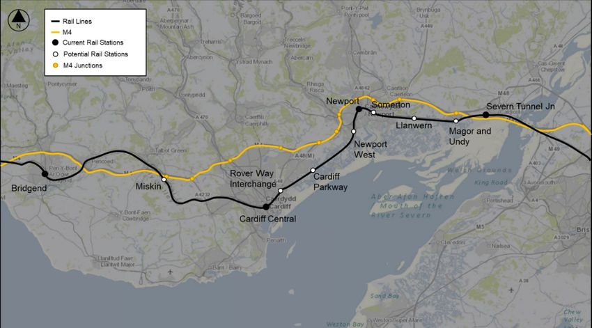
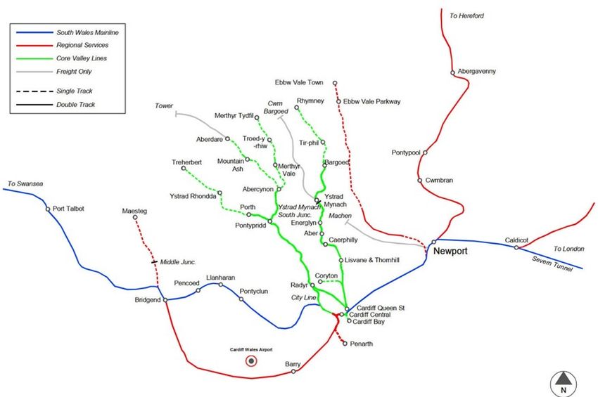
1.2 The rail network in South East Wales is as shown in Figure 1.1. Key features of this
network are noted in the diagram as being the following:
• South Wales Mainline (SWML)
• Branch lines and other routes serving various regions
• Core Valley Lines (CVL)
Figure 1.1: South East Wales Rail Network
Source: Mott MacDonald
1.3 The SWML is the main rail artery route in South Wales and broadly runs parallel to
the M4. The potential role for rail and the SWML in reducing traffic flows along the
M4 was identified early in the process.
1.4 Network Rail owns the majority of the UK rail network and is the infrastructure
manager for the SWML and other routes shown in red in Figure 1.1. It is responsible
2      Rail technical background

            for maintaining the railway at an agreed level, and where it can do so, upgrade the
            network to facilitate more trains running. It is also responsible for delivering an
            acceptable level of performance - the level at which is agreed with the DfT.

1.5         The Welsh Government has now taken ownership of the CVL from Network Rail, with
            plans to run faster, more frequent and greener services on all CVL routes. The
            responsibility for delivering this is with Transport for Wales (TfW) who are responsible
            for both the upgrade of the CVL and the operation of the Wales and Borders rail
            service.

1.6         The CVL comprises a network of railway lines that connect communities along the
            South Wales Valley corridors. The geography of the Valleys is such that the economic
            and social wellbeing of the area is heavily dependent on efficient transport links
            between the Valleys and centres of economic activity along the M4 and A465
            corridors. The CVL can be interpreted as a self-contained suburban rail network (that
            is well placed to compete with road transport).

1.7         Welsh Government have a number of aspirations and proposals for the SWML.
            Outside of the CVL, the Welsh Government ambitions for rail1 include a number of
            different potential services on the SWML alongside various other routes in South East
            Wales. The timeline and phasing of these are to be determined but would have a
            major impact on road traffic on the M4 and other key transport routes in Wales.

1   https://gov.wales/south-wales-main-line-rail-network-map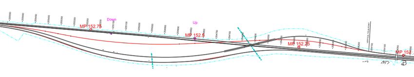
3   Rail technical background

2. Existing Infrastructure

2.1    The SWML is the arterial route connecting Cardiff with destinations across England
       and Wales. At Severn Tunnel Junction, the separate two track railways from Bristol
       and Gloucester merge to form a four-track railway.

2.2    This four-track railway then runs to Cardiff Central Station and is paired by direction
       between Severn Tunnel Junction and Bishton Flyover (MP 149.0 – MP 153.0) and then
       by function through Newport to Cardiff Central station. The Relief Lines occupy the
       southern pair of tracks and the Main Lines the northern pair (MP 153.0 – MP 170.25).

2.3    At present, passenger services tend to the use the northern pair of Main Lines, with
       freight services using the southern pair of Relief Lines. The signed line speeds of the
       Relief Lines are generally lower than the Main Lines due to a number of reasons
       including track condition and operational restrictions (due to the number of freight
       connections).

       Track

2.4    The existing Relief Line track is Track Category 3 or 4, but this assumption has not
       been confirmed at this stage. Details of the existing track components and age,
       maintained by means of the Network Rail GeoRIMN database, has not been fully
       reviewed for this study. However, the existing plain line track appears to comprise
       generally of CEN56 rail on concrete or timber sleepers. Short sections of CEN60 rail
       may be present about NR60 Mk 1 Switch and Crossing (S&C), that has been installed
       at various locations.

2.5    Switches and crossings located on the Relief Lines comprise of both CEN56 and NR60
       Mk1 geometric designs types, of varying ages.

2.6    Three long-timbered bridges have been identified in the Severn Tunnel Junction to
       Cardiff section.

2.7    Details of Network Rail’s proposals for domestic plain line and switch and crossing
       renewals planned for CP6 and CP7 have not been reviewed for the purpose of this
       study.
4 Rail technical background
Signalling
2.8 The signalling from Severn Tunnel Junction to Cardiff is considered to be in excellent
condition due to its recent installation. The area from Cardiff to Newport was re-
signalled under the Cardiff Area Signalling Renewals project (CASR) which finished in
2017. Under this project 300 signals were replaced with a modern like for like
equivalent, increasing the reliability and capacity of the Cardiff area. The area from
Newport to Severn Junction was re-signalled under the Newport Area Signalling
Renews project (NASR) which was finished in 2011.
Structures
2.9 A review of Network Rail’s Civils Asset Register and Reporting System (CARRS) has
identified 148 underbridge structures between Severn Tunnel Junction and Cardiff, 99
of which are culverts, 46 of which are underbridges and 3 viaducts. Overbridges have
not been reviewed as part of this study as it is assumed that the recent Great Western
Electrification programme (GWEP) has assessed these from a clearance and condition
perspective.
2.10 The bridge examination and detailed assessment reports have not been reviewed for
this study. Previous route assessment reports (Severn Tunnel Junction to Cardiff Relief
Lines – Line Speed Enhancements 664360-PRE-FS-620 July 2007 and 3.1.2 SWML
Linespeed improvements 141982-CAR-ERP-CV-312111 June 2015) suggest that the
strength of the existing structures on the route are sufficient, but that the 2No.
existing Longitudinal Timber Bridges on the Relief Lines at 154m 70ch and 156m 30ch
should be replaced with either ballasted deck bridges or a direct fastening bridge
decking system. It is noted in these reports that similar bridges on the Main Lines had
their decks replaced previously.
Overhead Contact System (OCS)
2.11 As part of GWEP, an OCS has recently been installed and commissioned on the SWML
as far as Cardiff Central.
2.12 It is expected that the OCS would not require significant modifications as part of any
line speed proposals other than adjustments from a height and stagger point of view
or S&C modifications.5 Rail technical background
Non-Traction Power and Telecoms
2.13 The SWML corridor between Severn Tunnel Junction and Cardiff Station has a
number of existing Distribution Network Operators (DNO) intakes and other trackside
services in the area which may be impacted by proposals to enhance capacity / line
speed on the Relief Lines.
2.14 The following Principal and Auxiliary Supply Points (PSPs and ASPs) have been
identified along the SWML: Leckwith PSP; Newtown PSP; Wentloog ASP; Ad Yard PSP;
Newport West ASP; East Usk Yard PSP; Magor ASP and Severn Junction Tunnel PSP.
2.15 It should also be noted that the SWML corridor is covered by a telecoms network
serving the various assets within the corridor. As noted previously, it is assumed there
is sufficient telecoms network capacity to accommodate the changes in data
communication for new stations and modifications to signalling infrastructure
SWML Infrastructure Review - Line Speed
2.16 This section looks at where potential line speed enhancements may be possible. It
should be noted that the assessment applies to the Up and Down Relief Lines only. A
track condition assessment has not been carried out for either the existing service or
potential future service levels.
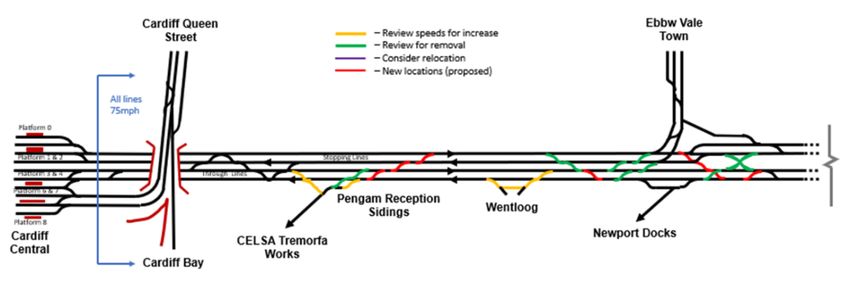
2.17 The schematic in Figure 2.1Error! Reference source not found. is an initial guide as
to where interventions may be required to achieve the operational line speed
improvements on the Relief Lines.6 Rail technical background
Figure 2.1: Proposed Operational Schematic
Source: Mott MacDonald
2.18 For the study, a line speed of 75 mph was used as the maximum practical speed
targeted for the Relief Lines, based on the infrastructure that exists today. This speed
is the maximum speed permitted on through routes with S&C design speed of 25
mph used with signal controls with flashing aspects. For line speeds of 80 mph and
above, 40 mph S&C would be required to be compliant for flashing aspects. Below
the threshold speeds ‘Main Approach from Red’ (MAR) signalling controls would
require trains to brake to a speed of less than 25 mph or a standstill on the approach
to junction signals, which would have a significant impact on capacity for the Relief
Lines. As the majority of S&C that exists today on the route is 25 mph or less, and7 Rail technical background
replacement costs to upgrade these to 40 mph would be high, 75 mph was the target
speed used.
Track Review
2.19 In the following text, alterations to the existing infrastructure are described in the
direction of increasing mileage, irrespective of the normal direction of running.
Severn Tunnel Junction to Magor Closed Station (MP 149.0 – MP 151.25)
2.20 The tracks are paired by direction over this section, with the Down Lines being
located on the southern side of the corridor. The railway was originally built with twin
tracks before increasing to four tracks in the 1940s. The original tracks are the central
pair (Up Relief and Down Main) with the additional tracks being added on either side.
Structures were extended, with the existing abutments remaining in the space
between each of the new Up and Down Lines, and island platforms provided at
Magor station.
2.21 As a result of the greater separation required at the overbridge structures and former
platforms, the Relief Lines are located on a more restrictive alignment than the Main
Lines. This section would therefore require more extensive realignment and re-
canting to achieve the target speed of 75mph.
2.22 Whilst it has generally been possible to retain the revised alignment within 100mm of
the existing track centrelines, maximum slews through this section are in the order of
800mm, albeit over relatively short sections. However, the alignment designs are
indicative and could be refined to reduce the slew magnitude at a later design stage.
2.23 Some additional separation between the Main and Relief Lines in both directions may
be possible to increase the width of the proposed new Main Line platforms at Magor
and Undy new station. Due to the realignments proposed in the Magor area, which
requires re-canting of the track, the existing crossovers in the area require
replacement. They are currently located on curved track and the proposal would be
to move them west to the next section of straight track.
2.24 Gradients are generally flat within this section, with the maximum gradient being 1 in
300 about the former Undy station site.8 Rail technical background
Magor Closed Station to East Usk Junction (MP 151.25 – MP 156.75)
2.25 The tracks are paired initially by direction over this section, with the Down Lines being
located on the southern side of the corridor. At Bishton Flyover, the Up Relief Line
crosses over the Main Lines on a structure and relocates between the Down Relief
and Main Lines, with the tracks now being paired by function (Main and Relief)
onwards to Cardiff.
2.26 The existing alignment for both Relief Lines about Bishton Flyover has been assessed
and concluded that it could potentially be increased to 50 mph (existing speed is 40
mph). This could be achieved by increasing transition lengths and the provision of
additional cant, with both tracks remaining on their existing formations.
2.27 Alternatively, an option has been developed to provide 75 mph alignments on both
Relief Lines around Bishton Flyover. This would require a revised alignment on the
Down Relief Line with slews estimated at 1.5 m at various points along the alignment.
This would require formation widening and replacement of at least one bridge over a
water course.
2.28 For the Up Relief Line, a new alignment, served by a new flyover structure located to
the west of the existing bridge would be required with flatter curves and new
earthworks. The proposed alignment has been designed to fit between existing
constraints of Llandevenny Road overbridge to the east, and the Bishton Road
underbridge and level crossing to the west.
Figure 2.2: Indicative 75mph Up Relief Line alignment (Existing in grey, new alignment in red)
Source: Mott MacDonald
2.29 Consideration was given to increasing the Relief Line speed to 90 mph to match the
existing High-Speed Train (HST) limit on the Main Lines. However, the presence of the
flyover, for which the practical maximum speed limit is 75 mph, does not make this
option viable. A line speed of 75 mph is deemed to be feasible over this generally
straight section of track, however some realignment of the Relief Lines may be9 Rail technical background
required. This is due to the long straight being essentially a number of shorter
straight elements connected by flat radii curves to facilitate the change in bearings.
2.30 Gradients remain generally flat and undulate over this section, with the maximum
gradient being 1 in 290, both at Llanwern East Junction and on the approach to
Llanwern West Junction.
East Usk Junction – Usk Yard West Junction (MP 156.75 – MP 157.50)
2.31 The line speeds are 40 mph on both Relief Lines, with a section of 60 mph on the
Down Relief Line between Llanwern West Junction (c. MP156.0) to Usk Yard West
Junction (c. MP 157.5).
2.32 The Relief Lines continue on a parallel alignment to the Main Lines until the A455
Spytty Road overbridge, near East Usk Junction, where they deviate to pass round the
intermediate bridge abutment pier, located between the Relief and Main Lines.
2.33 The existing alignment contains a crossover (8060 pts) between the Relief Lines
located on curved and canted track. As it is not deemed practical to provide
additional cant to accommodate a 75 mph through alignment speed, revised
alignments have been developed for both Relief Lines, taking the opportunity to
provide a suitable length of straight on which to relocate the crossover. A 75mph
through alignment would therefore be feasible, continuing from the Llanwern area
through East Usk Junction as far as Usk Yard West Junction at mileage 157M 53ch.
2.34 The gradients generally rise over this section, with a summit at MP 156.75. The
gradient then falls toward East Usk Junction before rising again to Maindee East
Junction. The maximum gradient falls at 1 in 200, on the approach to Usk Yard
Usk Yard West Junction to Newport Station East (MP 157.5 – MP 158.5)
2.35 The existing line speed on both Relief Lines is 40 mph through this section, which is
the same as that of the Main Lines.
2.36 The crossover (8070 pts) between the Relief Lines, which provides an Up direction
connection to Usk Yard, is located on a curve that would require realignment and re-
canting in the event of speed increases. As the relocation of the crossover was not
deemed possible due to a number of underbridge structures in the area and
insufficient space, and retaining the crossover with increased cant was deemed not
practicable, it was concluded that the current crossover be retained.
2.37 No line speed improvement is therefore proposed for this section, noting they would
be identical to the Main Lines through this section10 Rail technical background
Newport Station East to Newport Tunnel East (MP 158.5 – MP 159.0)
2.38 The existing line speed on both Relief Lines remains at 40 mph through this section,
with 20 mph through the platform loops.
2.39 Line speed improvement are not proposed on the Relief Lines through this section,
which would remain at 40 mph. This is driven by the fact that the curvature through
this area is tight and all trains are proposed to stop at the station.
2.40 Alterations to Newport Station are proposed.
Newport Tunnel East – Gaer Junction West Crossovers (MP 159.0 – MP 160.75)
2.41 The existing line speed on both Relief Lines is 40 mph from Newport station to
approximately MP 160.5 at the site of Newport West Station, where it increases to 60
mph, once clear of Ebbw West crossovers.
2.42 The existing gradient rises towards through Newport Old Tunnel, with a maximum
gradient of 1 in 331 to a summit towards its west end and then falls through Gaer,
Alexandra Dock Yard and Ebbw Junctions and Ebbw crossovers to the limit of this
section at MP 160.75, on a maximum gradient of 1 in 150 at Gaer Junction.
2.43 There is a lot of S&C through this section, much of it historic and no longer required
for the operation of the proposed timetable under normal conditions.
2.44 The target for speed improvement for this section is 60 mph. This is deemed to be
achievable with a certain amount of realignment and re-canting, particularly on the
curved track section from the Tunnel West to Gaer Junction. In order to achieve the
increase in speed, it would be proposed to remove the crossover connections located
on curved track, which would effectively remove connections between the Relief and
Main Lines in this section.
Gaer Junction West Crossovers – Rumney River Bridge Junction (MP 160.75 – MP
167.75)
2.45 The existing line speed on both Relief Lines is 60 mph from Ebbw West crossovers to
167M 49ch near Rumney River Bridge Junction, where it reduces to 40 mph through
the S&C connections to Pengam Yard.
2.46 A proposed line speed of 75 mph is deemed to be feasible over this generally straight
section of track, however some realignment of the Relief Lines may be required. This
is due to the long straight being essentially a number of shorter straight elements
connected by flat radii curves. Increasing the line speed may require alterations to11 Rail technical background
these curves to ensure the track geometry parameters remain within normal track
geometric limits.
Rumney River Bridge Junction - Cardiff East Junction (MP 167.75 - MP 170.25)
2.47 The existing line speed on both Relief Lines continues at 40 mph from Rumney River
Bridge Junction to Cardiff East Viaduct Junction, apart from a short section of 75 mph
on the Down Relief Line between Moorland Road and Newton Junction, which
permits the Down direction crossover at Moorland Road Junction to operate at the
Main Line speed of 75 mph through this section. Line speeds reduce from 30 mph at
East Viaduct Junction to 15 or 20 mph within the station limits.
2.48 A proposed line speed of 75 mph, continuing from Rumney River Bridge Junction, is
deemed to be feasible as far as the eastern end of the S&C at Newton Junction, from
which the existing 40 mph speed would be retained towards Cardiff Central Station.
2.49 Line speed improvement over this section would require realignment and re-canting
of the Relief Lines at Rumney River Bridge Junction with two crossovers and one
turnout being relocated onto the revised alignment.
2.50 The existing vertical alignment remains on a flat, undulating geometry through most
of this section, but starts to rise towards Cardiff Central station at MP 169.75. The
maximum gradient approaching Cardiff Central station is 1 in 80.
Signalling Review
2.51 A signalling assessment determined the maximum permitted line speed by braking
distance and gradient along against the existing signal to signal distances and
compare this against Railway group standard GKRT0075 (Requirements for Minimum
Signalling Braking and Deceleration Distances).
2.52 The conclusions to draw from this work is that the line speed enhancements
proposed are likely to be possible without significant modification to the existing
signalling system. The significantly higher achievable speeds show that trains on the
Relief Lines are considerably over-braked resulting in underutilisation in terms of
capacity.
Structures Review
2.53 A preliminary review of the implications of the proposed increases in Relief Line
speeds on structures between Severn Tunnel Junction and Cardiff Central has been
carried out.12 Rail technical background
2.54 The Section Appendix for the route notes that the route is satisfactory for RA8 (Route
Availability 8) live loading and hence each structure is currently satisfactory for at
least RA8 loading at the present line speed. Increasing the line speed, however, would
increase the dynamic factor on the live load and result in increased total design load
on the structure. Referring to the information from the CARRS database it is noted
that the RA ratings are given for some of the underbridge and viaduct structures and
vary between RA8 and RA15. The structures rated as RA15 would likely have ample
reserve to allow for increased line speed, but the structures at RA8 could require
strengthening.
2.55 It is recommended in the next stage of the design to obtain the assessment reports in
order that the structure requirements may be clearly established. To provide an
indication approximately 10% of the structures concerned have been reviewed. The
main conclusions drawn from this limited assessment is that a number of structures
are likely to have more than 20% increase in live load and such are more likely to
require further assessment and possible strengthening.
SWML Infrastructure Review - Junction Interventions
2.56 This section focuses the junctions across the route and the options to increase
capacity and support the line speed proposals above. This has primarily focussed on
track alignment, with input from signalling where applicable.
2.57 Existing S&C will need to be inspected for condition, including ballast depth, as it will
need to meet the requirements of Track Category 1 or 2 in the event of the Relief
Lines operating additional trains at a higher speed. The implication is that the older
S&C in the study area may require replacement on a like-for-like basis to satisfy Track
Category or minimum condition requirements. This will apply even if the particular
unit does not need to be relocated on realigned track to enable the higher line
speeds.
Severn Tunnel Junction
2.58 The existing line speeds on through alignments and S&C were deemed to be
satisfactory for the purpose of line speed improvement. Increasing speeds through
the branch routes of S&C was not deemed to provide a significant benefit for the
current operational concept.13 Rail technical background
Magor Crossovers
2.59 Two options were considered for the track realignment necessary to achieve higher
speeds and accommodate a new station in the area. Both options would provide
crossover speeds of 40 mph. The evaluation of a preferred solution is subject to
further study.
2.60 Option 1 relocated the crossovers 50m to the west, with the Relief Line turnouts
being placed on a straight section of track enabled by the realignment of the Relief
lines at Magor. This would however result in the Down Main Line turnout being
located partially under an overbridge, which may have implications on maintaining a
compliant clearance offset to the intermediate bridge pier located between the Down
Main and Down Relief Lines.
2.61 Option 2 relocated the crossover onto a straight, parallel alignments 560m from their
existing position.
Bishton Flyover
2.62 The previous section presented two options for enhancing the speed of the Relief
Lines:
• Increase speeds from 40mph to 50mph by re-canting on the existing
formation; and
• Constructing a new flyover structure to the west to provide higher speeds of
75mph
2.63 The cost benefit analysis of these solutions to select a preferred option would be
subject to further study.
Llanwern Exchange Sidings East Connection
2.64 The existing double junction has been relayed approximately within the last 10 years
with a CEN56 CV or DV double junction on concrete bearers. No alterations are
proposed to this junction from a track perspective, subject to future confirmation of
condition and compliance with track category for the expected tonnage.
Llanwern Exchange Sidings West Connection
2.65 The existing double junction is thought to be a CEN56 CV double junction on timber
bearers. On this basis it is likely to be more than ten years old. This condition of this14 Rail technical background
junction will need to be assessed and may need to be replaced on a like for like basis
if the condition dictates.
2.66 There is a desire to increase entry speeds into Llanwern Exchange sidings from
15mph to 25mph at both ends to free up capacity on the Relief Lines. However, there
are MAR restrictions on the route from signal NT1245 to NT6019 which is a
permanent stop board located within the siding facility. This MAR restriction is driven
by the fact the sidings themselves are restricted to 15mph and the permanent stop
board locations are located just within the facility which requires trains to start
braking on the Relief Lines in order to stop at the board.
2.67 MAR is a restrictive form of junction control designed to impose a speed reduction
such that a low speed divergence can be safely negotiated. In practice a train that is
routed in to Llanwern Exchange siding from Severn Tunnel will be shown a red signal
at NT1245. When the train has occupied the berth track circuit for a period of time
the signal will step up to a yellow and the Position Light Junction Indicator (PLJI) will
illuminate, allowing the driver to proceed.
2.68 In order to lift the MAR restrictions on signal NT1245, the feasibility of changing this
to a yellow flashing aspect sequence was investigated. Unfortunately, because the
siding is classed as a terminal line and all trains will have to stop, the proposal
contravenes the signalling standard “Requirements for colour light signalling”
NR/L2/SIG/19609 chapter 10.1.1-C.
2.69 With MAR restrictions having to be retained another option was explored whereby an
extra signal is installed within the siding to create another block section so that a
train could enter the siding on a yellow flashing sequence. However, there is
insufficient length to install this block section.
2.70 Based on the current configuration and not undertaking significant modifications
within the sidings themselves, the remaining option is to speed up the process of
allowing trains off the Relief Lines. Currently trains need to occupy track circuit DBJ
after signal NT1243 for 54 seconds before the signal will step up and allow the train
to proceed into the siding. By cutting the time that the track circuit needs to be
occupied, potentially 20-25sec could be saved. This option would also require the
need to insert new train detection section splitting up the current long DBJ track
circuit.15 Rail technical background
2.71 The issues highlighted above for the eastern entrance into Llanwern Exchange sidings
also apply to the western entrance in terms of principles. As these sidings are owned
by TATA Steel, TATA are responsible for what happens in their yard.
East Usk Junction
2.72 The existing S&C is thought to comprise a 30 mph CEN56 crossover and a pair of
CEN56 25 mph turnouts on timber bearers (signed for 10mph). The age of the S&C is
thought to be more than ten years.
2.73 New S&C is proposed for the crossover and turnout connections from the Relief Lines
to the Up and Down Uskmouth Line, which serves as a reception road. This is due to
the proposed realignment and re-canting of the through alignments to achieve
higher speeds. The proposed S&C has been designed to fit on straight alignments
provided by the Relief Line realignment proposed about this section of track with a
design speed for the S&C being 25 mph.
Usk Yard West Junction
2.74 As it is not proposed to increase the Relief Line speed in this section, no alterations
are proposed for the existing S&C in this section, with replacements being carried out
on a like for like basis if condition requires.
Maindee East and West Junction and Crossovers
2.75 As this junction is located on the Main Line side of the tracks and not impacted by
proposals to increase the Relief Line speed, no alterations are proposed for any S&C
in this section.
East Usk yard signalling
2.76 The entrance to East Usk Yard is MAR controlled which will need to remain in place.
However, all moves into the sidings are shunt moves i.e. there are no Main Line
moves into the sidings. In practice it is more restrictive to enter East Usk Yard, as
trains will have to come to a complete halt at signal NT1253, then the position light
signal will illuminate in conjunction with the miniature indicator allowing the train to
proceed into East Usk yard.
2.77 It is possible that signal NT1253 can be moved closer to the yard turnout which
would minimise the distance travelled at 15mph for any shunt moves to free up
capacity on the Relief Lines. The signalling plan S1224-2-1 Magor – East Usk does not16 Rail technical background
show where these shunt moves terminate, however it is assumed there they terminate
on the individual reception lines within the siding.
2.78 Another safety reason for the current low linespeed into the yard is that handpoints
exist in the yard. These require the driver of the train to exit the train and crank the
points over to the desired position before traversing the points. It may be possible to
change these to motorised switches to reduce shunting time.
2.79 Unless there are significant modifications made to the yard itself, due to the fact that
there are only shunt moves into the siding, speeds cannot be raised above 15mph.
However, there is no reason why the speed cannot be increased to 25mph when
exiting East Usk yard.
Newport station signalling
2.80 The only modifications proposed in the Newport Station area relate to the Down
Passenger Loop. The existing S&C is thought to comprise of a 20 mph CEN56 turnout
on concrete bearers at the east end and a 20 mph NR60 Mk1 turnout at the west end.
The proposal is to remove the loop to facilitate higher entry speeds for Intercity
services stopping at the station. Therefore, both turnouts would be replaced with
plain line. The age of the S&C is thought to be less than ten years.
2.81 The proposed removal of the bi-directional loop will require the recovery of signal
NT1366 and for it to be moved to the new platform location on the Down Relief Line.
All other signalling equipment that is currently on the platform loop will need to be
recovered and moved to the new platform location too, Signal NT1369 would be
entirely abolished as there is no appropriate location to move this signal to.
Gaer, Ebbw Junction and Ebbw West Crossovers Area
2.82 Extensive alterations to the existing S&C are proposed in this section, with much of
the S&C that provides crossover connections between the Relief and Main Lines
being removed, in order to enable the Relief Line speed to be increased from 40 to
60 mph, which would facilitate a valuable journey time improvement through this
section.
2.83 Without the removal of S&C on curved track, the proposed line speed improvement
would not be feasible, as it would not be possible to provide the transition lengths
required for the higher speed and retain the existing S&C footprint.
2.84 As a result of the removal of the Main and Relief Line crossovers, movements
between these lines would be as follows for the wider Newport area:17 Rail technical background
East of Newport station:
• Up Main to Down Relief ladder in the Up direction: existing crossovers located
between Usk West and Maindee East Junction (20 mph - both directions)
• Up Main to Down Relief ladder in the Down direction: crossovers between
Maindee East Junction and Newport Station East (20 mph - Up and 30 mph –
Down directions)
West of Newport station:
• Up Main to Down Relief ladder in the Up direction: crossovers located on
straight track to the east of Ebbw Junction (40 mph - both directions)
• Up Main to Down Relief ladder in the Down direction: no crossovers will
remain. However, if movements in this direction are required to be retained,
then a new ladder at a higher speed could be located on the straight track
section to the west of MP 161.5
Wentloog East Junction
2.85 The existing S&C is thought to comprise CEN56 25 mph S&C on timber bearers,
signed for 20 mph. The age was not determinable from the available information.
2.86 The possibility of 25 mph connections into the Freight Terminal was evaluated. The
length of track between the crossover and turnout is not suitable for the follow-on
distance, which would apply to trains leaving the terminal in the Up direction and
using both the turnout and crossover. This is unless exceptional range design values
are deemed to be acceptable for this situation by Network Rail. Otherwise the
crossover would require relocating 10m to the east to achieve practical compliance.
Wentloog West Junction
2.87 The existing turnout is thought to comprise CEN56 25 mph unit on timber bearers
and signed for 25 mph. It is proposed that the turnout remains as existing, subject to
condition.
Wentloog Junction review by Signalling
2.88 The existing route into Wentloog siding is a shunt move from signal CF2209 to the
permanent stop board CF7003 within the siding. Raising of the speed of this turnout
is advised against due to the short braking distance between the set of points (9003)
and the stop board within the sidings. There are two hand points that would need to18 Rail technical background
be in the correct position for the train to enter the siding as well as a Shunters
Acceptance Plunger.
2.89 An option exists to change the hand points to motorised switches to reduce track
occupation time to release capacity but would not enable the speed of the turnouts
increase. However, there is no reason why the speed cannot be increased to 25mph
for trains that are leaving the yard on to the main lines.
2.90 It should be recognised that Wentloog is privately owned and outside of the Network
Rail maintenance boundary. Any change to the layout or speed of the route into the
siding would ultimately be futile if the line speed within the siding was not also
increased. This would need to be agreed to by the siding owner.
Rumney River Bridge Junction
2.91 The S&C at Rumney River Bridge Junction provides connections between the Main
and Relief Lines and Pengam Yard and Cardiff Tidal Sidings, via a short branch. The
existing S&C arrangement is thought to comprise of the following:
• A NR60 Mk1 crossover on concrete bearers between the Main Lines
• Two CEN56 S&C crossovers on timber bearers between the Down Main & Up
Relief Line and Relief Lines respectively
• Followed by a CEN56 turnout on timber bearers from the Down Relief Line to
Pengam Yard
2.92 All S&C is thought to be designed for 25 mph, but the turnout is signed for 15 mph.
The NR60 S&C is thought to be newer than ten years old, with the CEN56 S&C
probably older than ten years.
2.93 Due to realignment of the Relief Lines to achieve a 75 mph line speed, the CEN56
S&C would require replacement, with the Down Main to Up Relief crossover requiring
both replacement and relocation to the east to accommodate an alignment
transition. The NR60 Main line crossover is thought to unlikely to require
replacement, subject to condition.
Pengam Junction
2.94 The S&C at Pengam Junction provides a connection between the Relief Lines and the
west end of Pengam Yard. As the S&C is located on straight track, its geometry will
not be affected by the proposed line speed improvement to 75 mph. Any19 Rail technical background
replacement would be subject to condition and compliance with the requirements for
S&C at Track Category 1 or 2.
Cardiff Central Approach
2.95 S&C located between Moorland Road Junction and Cardiff East Junction comprises
modern NR60 Mk 1 units and has probably been installed in conjunction with the
Cardiff Area Re-signalling project, which is due to be completed in 2020.
2.96 Some of the S&C shown on the 2013 lidar survey and images used for this
assessment has been removed and other units have been included in the layout.
2.97 Most of this S&C is located on straight track, so would not be affected by potential
line speed improvements, and where located on curved and canted track, these are
the beyond the limit of the proposed 75 mph line speed improvement so would not
be impacted.20 Rail technical background
3. Further Impacts Outside of SWML Operational Scope
3.1 This infrastructure study has focused on the required SWML track modifications and
associated signalling and structures implications to meet the operational aspirations
stated at the beginning of this report. However, there are also potential wider
implications of these proposals on other lines and nearby stations, as briefly
explained below.
Maesteg Branch
3.2 The current loop at Garw, is currently out of use. To enable the 2tph on the branch,
this loop will need to be reinstated, (along with a possible relocation of Tondu station
to improve performance by enable the calling point to be within a passing location)
and lengthened at both ends.
Ebbw Vale Branch
3.3 As part of the new Wales and Borders service, there is a planned additional service
operating on the Ebbw Vale branch between Ebbw Vale Town and Newport. To
deliver this increase in service frequency, requires the following alterations:
• A doubling of the track between Park North Jn and Rogerstone
• The Ebbw Vale Frequencies Enhancement Scheme (a proposed extension of
the existing passing loop by 7 miles)
• A loop between Cwm and Ebbw Vale Parkway
These changes may be subject to alteration depending on what timings are
proposed for services on and off the branch, and the service interval applied.
Marches Line
3.4 The South Wales Metro concept provides the opportunity to meet some long-held
aspirations on the Marches route. These aspirations include:
3.5 Enhanced service frequencies through the introduction of a half hourly local stopping
service to Abergavenny or Hereford.
3.6 Journey time reductions for long distance services to Manchester and Holyhead
through the removal of intermediate stops south of Hereford.
3.7 The provision of additional station calls at new or re-opened stations.21 Rail technical background
3.8 If these additional services are to terminate at Abergavenny the following are
required:
• The reinstatement of a Cardiff facing bay platform
• New signalling and track to connect the bay platform to the Marches line
3.9 If these services are to terminate at Hereford the following is required:
• Additional intermediate block signals in the Little Mill Area to provide the
required track capacity for increased passenger services, and existing freight
traffic
Infrastructure Summary
3.10 This high level infrastructure review has concluded that from a track horizontal
geometry perspective, line speed improvements over existing speeds on the Relief
Lines are likely to be viable over large extents of the route between Severn Tunnel
Junction and Cardiff Central. This viability review supports the operational aspirations
presented as part of this study. However, several track interventions are required to
achieve these aspirations.
3.11 A summary of the potential speed changes on the Relief Lines are as follows in Table
3.1. All changes are based on the Down Relief line with only subtle changes to the
below for the Up Relief. Red indicates where line speed improvements are proposed.22 Rail technical background
From To Existing Down Proposed Down
Relief Relief
Miles Chains Miles Chains Speed (mph) Speed (mph)
149 14 149 24 70 70
149 24 149 74 40 75
149 74 156 05 60 75
156 05 157 46 40 -
156 05 157 57 - 75
157 46 160 30 40 -
157 57 158 64 - 40
158 64 159 60 - 60
159 60 169 46 - 75
160 30 167 49 60 -
167 49 168 69 75 -
168 69 169 53 40 40
169 53 170 08 25 25
170 08 170 20 15 15
Table 3.1: Proposed Relief Lines Speed Increase
Source.: Mott MacDonald
3.12 Releasing capacity to run Intercity services amongst Freight services on the Relief
Lines however, largely relies on improved connection speeds into the various sidings
and freight facilities. The infrastructure review has concluded that this presents some
challenges from a signalling perspective which may only be overcome through more
extensive remodelling works. This needs to be explored further as part of further
design work, along with assessing the ability to still meet the operational aspirations
based on current restrictions.23 Rail technical background
New and Existing Stations
3.13 As part of this study, analysis was undertaken to identify the main commuter flows
along the M4. These flows were overlaid against the rail network in order to
determine where high origin and destination journeys align with current or proposed
rail stations.
3.14 This SWML corridor study has considered the identified stations in more detail to
review the technical feasibility of them.
Figure 3.1: Potential and Existing Station Locations
Source: Mott MacDonald24 Rail technical background
4. Newport West Station
4.1 The SEWTC have considered a potential new station located to the West of Newport.
This section looks at the possible station location and layout, the track and civils
infrastructure and local access arrangements.
Station Characteristics and Location
4.2 The purpose of Newport West station is to create a transport hub. This would enable
a modal shift from car to rail, providing improved public, shared and active travel
connections to and from the station.
4.3 Error! Reference source not found. shows the population and employment density
in 2030 for the surrounding area of Newport West which has been adjusted to take
into consideration the nearest station for passengers.
Within 2k (2030) Within 5k (2030)
Population 15,000 25,000
Employment High High
Table 4.1: Nearby population / employment density (2030)
Source: Office of National Statistics, factored to 2030
4.4 The station is expected to include a local bus service. The existing bus service along
the A48 (Docks Way) only operates every two hours in each direction (Routes 35 and
36). The introduction of Newport West station could therefore justify a more frequent
bus service.
4.5 Proposals for the station include a small car park for short stay and disabled parking.
Electric vehicle charging points could also be incorporated as part of the hub. Secure
cycle parking to accommodate 50 bicycles was also recommended, with cycle hire
included as a possibility to support a core network of hubs across Newport.
4.6 At Newport West, the SWML is a four-track railway that is currently paired by
function, with the Relief Lines occupying the southern pair of tracks and the Main
Lines the northern pair (153m 0ch - 170m 25ch). As shown by the sectional
appendices section in Figure 4.1, the four SWML tracks in the scope area are
unidirectional. The area of interest is located between approximately 160m 0ch and
160m 40ch SWM2, where the existing line speed is 75mph on both Main Lines from
Newport station to approximately 160m 40ch. Moving southwards, the Main lines25 Rail technical background
speed then increases to 75 / HST 95mph heading towards 167m 49ch near Rumney
River Bridge Junction.
4.7 Along this section of route, there are a number of junctions. The Ebbw Vale branch
junction is on the west side of the SWML and the Alexandra Dock freight connections
to the east side of the SWML. There are 2 overbridges located at Lime Kiln bridge
(160m 15ch) and for the A48 (160m 18ch). There is also an underbridge at 160m 20ch
where the SWML crosses the Ebbw River.
Figure 4.1: Western route Sectional Appendix WR2
Source: Network Rail
4.8 As part of the operational concept, the proposed station at Newport West would be
located on the northern pair of lines, serving the stopping services only. This means
the services calling at Newport West and coming off the Ebbw branch would not
conflict with the operation of the intercity services. The station is planned to be
served by 4tph with the indicative timetable produced suggesting these services
include the:
• Miskin to Gloucester Services
• Bridgend to Bristol Parkway Services
• Maesteg to Ebbw Vale Services
• Engineering Considerations26 Rail technical background
Track
4.9 For a platform to be introduced between the main lines on the SWML, slewing of the
Up Main will be required. There are two overbridges, in proximity to a potential
station, which prevent slewing due to the bridge piers located on the west side of the
Up Main. This could impact the length of platform, line speeds and track with the
alignment potentially having to be slewed over to the access road to the west of the
SWML
4.10 The actual length of tracks slews will depend on the type and number of platforms
needed. Line speeds will also need to be considered, with higher speed lines
requiring longer sections to be altered.
4.11 A station at the bottom of the Ebbw Vale Branch will impact on the operation of
Ebbw junction. With numerous switch and crossings (S&C) in the area, certain
platform arrangements might benefit from the removal / relocation of some units
4.12 Any new S&C will also be constrained in certain areas, such as the Ebbw Vale branch
due to the horizontal curves. New connections around the overbridges would also be
an issue as it introduces a derailment risk next to the structures.
4.13 Slewing towards the track access road could result in the need to replace Ebbw River
underbridge as the loads introduced by the passing of trains may be higher than its
current capacity.
4.14 Any track slew could also impact on two of the nearby Relocatable Electrical Building
(REB). These buildings house various equipment for the operation of the railway and
would require planning to not impact on the operational railway.
Signalling
4.15 A new station could impact the existing signalling in the area with three signal
gantries within close proximity. Where possible, platforms should be placed on the
approach to existing signals rather than directly afterwards. Platforms should also be
kept outside of signal overlaps, to prevent the need for relocating existing signals.
4.16 By placing platforms closer to junctions, more potential issues are likely to arise,
resulting in more alterations, i.e. relocating / introduction of new signals. Ideally, the
introduction of new signals should be kept approximately 190m from turnouts /
clearance points to meet signal overlap requirements.27 Rail technical background
Overhead Contact System (OCS)
4.17 A review of the existing OCS is necessary to identify the changes required to
introduce a station in this area and to determine the impact the OCS infrastructure
has on the platform locations. The new station will affect the existing OCS heights as
a 3500mm electrical clearance is required from the live part of the pantograph to the
platform. The contact wire will need to rise from the current height passing under
A48 overbridge and Lime Kiln overbridge, to provide the necessary electrical
clearance from the live part of the pantograph to the platform. The permissible
gradient at which the contact wire can be raised from the bridges to the station is
based on the track speed and will determine the minimum distance required between
the bridges and the station’s platforms.
4.18 If there are any canopies present at the station, they must be electrically clear of any
live OCS and bonding checks will be required.
Option Review
4.19 A number of options were considered for the location of the station and its platforms.
Following an initial review, 3 options were selected for more detailed assessment.
Figure 4.2 shows the general arrangements of each of the selected option, showing
how the existing railway infrastructure could be impacted by the proposals.28 Rail technical background Figure 4.2: Arrangement of Selected Options Source: Mott MacDonald
29   Rail technical background

       Track Review

4.20 The following track analysis is based on Five Mile Diagrams and aerial imagery.

       Option 1

4.21 This proposal has significant impact on the Ebbw Junction and may result in
       operational deficiencies and increased infrastructure changes including S&C
       renewals and bridge reconstruction to achieve.

4.22 The Ebbw connection and the Island Platform serving the Ebbw Bay line and the
       Up Main has relatively little impact on the Track alignment as whole but would
       import complexity to the ongoing maintenance. The additional spur to serve
       the bay platform requires an additional connection to be installed on a tight
       radius curve.

4.23 A switch diamond arrangement would not be acceptable due to the curvature;
       therefore, this connection would need to encompass a crossover to connect the
       Down Cardiff Curve. This would still represent an operational risk (from failures)
       and a maintenance burden due to the curvature. Therefore, running services bi-
       directionally closer to Park Junction where there is a length of straight should
       ideally be considered instead.

4.24 The location of the island platform will require the REB adjacent to the DB
       Cargo access bridge to be relocated, which will take significant planning to
       avoid impacting on the operational railway. However, this will be further
       impacted by the Island Platform which will have significant impact on the
       overall junction.

4.25 The new Island Platform serving the Down Main line would require the Up Main
       line be relocated by approximately 3m to the west. This would account for the
       platform width (3.5m assuming fencing and platform furniture) and the
       structure clearance to the rear of the platform for the Up Relief Line. This
       relocation of Up Main would require the connection to the Up and Down
       Cardiff Curves to be replaced which may result in tightening up the curves on
       the approach. This realignment will require the REB located adjacent to this
       junction to be relocated. Additionally, the through line speed of 75mph would
       not provide the opportunity to locate an island platform of any useable length
       north of the bridge, and to achieve a compliant alignment tie in, prior to the
       bridges. This distance between the existing Cardiff Curves connection on the
       Down Main to the DB Cargo access bridge is approximately 180m.
30 Rail technical background
4.26 The Up Main would therefore need to pass through the third spans of both the
DB Cargo access bridge and the A48 overbridges. It would then pass over the
Ebbw River underbridge along the route of the track access road, which is
currently used as a maintenance access road, this is also where the REB
described above is located.
4.27 While there appears to be suitable clearance through the overbridges, they are
relatively modern, the Ebbw River underbridge is an aged box girder
construction. As the bridge previously took two railway lines, there is potential
the bridge could still be sufficient for a single line. A full condition assessment
would be required to determine if this bridge is suitable for the loading and a
cost / benefit analysis undertaken of refurbishment versus replace.
4.28 The relocation of the Up Main would also affect the associated S&C ladder (UR-
DM 8126AB and DM-UM 8121AB) with both crossovers requiring to be
relocated south of the Ebbw River underbridge. The revised transit time
through the junction will need to be compared with current junction margins to
identify if the margin needs increasing. If it does this will reduce capacity at the
junction. Points 8129AB and 8130AB many need to be moved further south,
further impacting on the operation of the junction.
4.29 Additionally, the island platform would interface directly with the crossover
between the Down Main and Up Relief (UR-DM 8120AB). While there is
precedent for S&C to be located within platforms, this would impact on the
operation of the railway at this location. This would also require additional
offsets in the coper edge to account for dynamic movement of trains (end
throw), adding risk to the travelling public and requiring deviation from Railway
Group Standards and potentially affecting the safety case of the station.
4.30 The revised Up and Down Cardiff Curves connections may provide opportunity
for this crossover to be relocated north of the station, subject to further review.
If this cannot be accommodated, it is likely to require the Relief to Main (UR-
DM 8120AB) and Relief to Relief (DR-UR 8127AB) connections to be located
south of the bridges as there is no opportunity for it to be relocated to the
north.
Option 2
4.31 The proposal for the island platform between the Main lines in this option
would include the issues as described in Option 1, although the island platform31 Rail technical background
configuration would require the Up Main to be moved north by approximately
5.5m to achieve minimum compliant useable width.
4.32 This option has reduced impact on the Up and Down Cardiff curves. While the
connections with the Up Main would need to be revised for the new alignment,
there is not the addition of the complex switch and crossing works associated
with a Bay Platform
Option 3
4.33 This proposal would locate the Up Main along the route of the track access
road as described in the above options in order to accommodate the island
platform to the south of the Ebbw River bridge. This will require the Ebbw River
bridge to be assessed and potentially replaced and the REB adjacent to the DB
Cargo access bridge to be relocated. (as per Options 1 & 2).
4.34 The revised alignment is also likely to impact on the Cardiff Curve connections
and the Up Main to Down Main crossover (DM-UM 8121AB) will need to be
replaced, but the overall footprint of the junction will be unaffected and
operational affect will be negligible.
4.35 The Ebbw Junction will still be impacted by the new station regarding the
southern ladder near the Ebbw River Bridge. The Mains crossover (UP-DM
8130AB) and Down Main to Up Relief crossover (DM-UR 8129AB) would need
to be relocated south should a 200m platform be specified.
4.36 There is less than 200m from the Ebbw Bridge to the point where the dynamic
affect associated with the Up Relief to Down Main crossover (UR-DM 8126AB)
would affect the Down Platform and may restrict any movement across the
ladder while the platform was occupied. A shorter platform could be
accommodated without affecting this S&C.
4.37 The offset of the Up Main in relation to the Down Main to accommodate the
Island Platform will require the Up Main to Down Main crossover (DM-UM
8121AB) to be replaced. This is due to the 75mph line speed which will require
the tie-in to the existing alignment to extend beyond the footprint of the
existing S&C.
4.38 Additionally, the existing Road Rail Access Point would need to be recovered
and potentially relocated elsewhere.32 Rail technical background
Signalling Review
Option 1
4.39 A connection from the Cardiff Curve into a Bay platform in Option 1, which will
include a crossover from the Down Cardiff Curve to Up Cardiff Curve, may
require signalling alterations to Park Junction interlocking. The signal Box at
Park Junction is currently an electro-mechanical installation. Network Rail is in
the process of decommissioning the signal box and incorporating its functions
into the Wales Rail Operating Centre (WROC) in Cardiff.
4.40 The Up Direction signals on the main and relief lines can remain in their present
longitudinal positions.
4.41 Signal NT1076 on the Up Main would ideally be 20m off the end of the station
platform to give adequate sighting standback, this would restrict platform
length to around 130m before the Lime Kiln Overbridge (DB Cargo Access road)
to the South.
4.42 It may be possible to retain the signalling gantry structure across Ebbw Junction
with the realigned Up Main track, however Signalling REB 160m 15ch, adjacent
to the gantry and the junction would need to be relocated.
4.43 In the Down direction (running towards Cardiff), the proposed platform on the
Down Main is within the overlap of Signal NT1075. This would be the worst
position from a headway/route capacity perspective as it results in a train
occupying two signal section during the time it is stopped at the station.
4.44 Depending on the chosen track configuration for the altered Main to Relief
ladder crossovers, there may be scope to relocate the Down Direction Signals
NT1075 (Down Main) and NT1273 (Down Relief) to the South of the platform
immediately before the Lime Kiln overbridge (which could reduce the platform
length by around 20m). However, this configuration would not be ideal for the
Goods Loop Down Signal NT1379, which would no longer be parallel.
4.45 Alternatively, a solution to move the Down signals around 170m north of their
present location could be looked into, but the current spacing appears to be
optimised for 75mph on the Main lines, and a reduction in that spacing would
mean reducing the speed, or imposing restrictive aspect sequences.
4.46 If the Down direction signals remain north of the station, with NT1075 on the
approach to the station stop, there is a risk of Start on Yellow, Signal Passed at33 Rail technical background
Danger (SOYSPAD) occurring after the station stop due to the distance of
1100m and curved approach to the next signal NT1079.
4.47 Any crossovers relocated South of the river Ebbw should ideally be clear of the
signal overlaps, at least 180m north of the Up direction Signal Gantry near 160
¾ Milepost.
4.48 To accommodate the realigned Up Main, the signalling power ‘AD Yard PSP’
REB type building, adjacent to the DB Cargo access road bridge would need to
be relocated, as would cable routes alongside the track, possibly including new
Under track crossings (UTX).
Option 2
4.49 This option, without the bay platform, has similar signalling constraints
described in Option 1.
Option 3
4.50 With this option the station would be sited more than 300m away from any
existing main signal positions.
4.51 Track changes to the crossovers Down Main – Up Relief (8129 AB), and Down
Main – Up Main (8130AB) south of the station site should ideally be
incorporated without impinging on the overlap of route setting signal NT1078
on the Signal Gantry near 160 ¾ Milepost. Independent Position Light signal
NT6074 on the Up Relief may need to be relocated.
4.52 Subject to a detailed track design, it may be possible to retain the signalling
gantry structure across Ebbw Junction with the realigned Up Main track.
4.53 To accommodate the realigned Up Main, the signalling power ‘AD Yard PSP’
REB type building, adjacent to the DB Access road bridge would need to be
relocated, as would cable routes alongside the track, possibly including new
UTX.
4.54 Departing from the station on the Down Main, there could be a possible risk of
SOYSPAD occurring due to a distance of around 700m and curved approach to
the next signal NT1079. Departing on the Up Main, the shorter distance to the
next signal, NT1076, will limit the achievable speed before the sighting point.You can also read