Robustness in Blind Camera Identification
←
→
Page content transcription
If your browser does not render page correctly, please read the page content below

Robustness in Blind Camera Identification
                                   Stamatis Samaras† , Vasilis Mygdalis† and Ioannis Pitas†?
                 †
                     Department of Informatics, Aristotle University of Thessaloniki, Thessaloniki, 54124, Greece
                          ?
                            Department of Electrical and Electronic Engineering, University of Bristol, UK
                                                    Email: pitas@aiia.csd.auth.gr

   Abstract—In this paper, we focus on studying the effects of var-   the sensor fingerprint from a set of images positively known to
ious image operations on sensor fingerprint camera identification.    have been taken by a particular camera. Once the fingerprint is
It is known that artifacts in the image processing pipeline, such     acquired one can prove that a given image under investigation
as pixel defects or unevenness of the responses in the CCD array
as well black current noise leave telltale footprints. Nowadays,      was taken by the exact same camera by using a signal detection
camera identification based on the analysis of these artifacts is     approach. A positive match between an image and a camera
a well established technology for linking an image to a specific      fingerprint ties the image with a very high certainty to its
camera. The sensor fingerprint is estimated from images taken         source camera. Without loss of generality the experiments
from a device. A similarity measure is deployed in order to           were conducted on cell phone cameras, due to their wide use
associate an image with the camera. However, when the images
used in the sensor fingerprint estimation have been processed         in everyday life.
using e.g. gamma correction, contrast enhancement, histogram             A standard sensor-based fingerprint identification method
equalization or white balance, the properties of the detection        for camera brand and model identification is proposed by
statistic change, hence affecting fingerprint detection. In this      Lukas et al. [3]. The same methodology has been used in
paper we study this effect experimentally, towards quantifying
                                                                      various related works [9],[1]. In July 2011 it passed the
the robustness of fingerprint detection in the presence of image
processing operations.                                                Daubert challenge 1 in the State of Alabama. That is, results of
                                                                      this method can be employed as evidence in court of law. By
                       I. I NTRODUCTION                               the term camera brand, we denote the camera manufacturer
   Source camera identification is a well studied problem in          (e.g., Samsung or LG), and by the term model, we denote
digital forensics [1], [2] over the past decade in various            the unique product name. Fingerprint detection pinpointing
domains. Most known applications are investigation, such as           the employed imaging sensor type and make is based on the
child pornography, image and video piracy or image authenti-          telltale effects created within the proprietary image formation
cation check (e.g. to detect malicious alterations of an image).      pipeline in cameras. Sensor fingerprints are essential artifacts
Nowadays, digital images can be easily edited and manipulated         due to charge couple device (CCD) sensor cell defects and
with sophisticated tools (i.e., image processing tools) ,not          minor make deviations from their standard type. That is, the
only for malicious but also for artistic purposes. Since such         fingerprint detection methodology is applicable to all digital
tools are available to a cell phone such manipulations alter          image devices that contain CCD or CMOS sensors.
not only the perceived image content but also the embedded               In this paper, we investigate the sensitivity of the identi-
camera fingerprint. This creates a robustness challenge to            fication performance against the aforementioned image ma-
standard source camera identification algorithms, such as [3],        nipulations. It is known that artifacts in the image processing
[4]. The vast majority of published work focuses on still image       pipeline, such as pixel defects or unevenness of the responses
source identification and only a handful of papers analyze the        in the CCD array and black current noise leave telltale foot-
effects of image alterations on its robustness [5], [6], [7]. The     prints. Nowadays, camera identification based on the analysis
most common image alterations tackled by published work               of these artifacts is a well established technology for linking an
primarily focus on geometric translations such as rotation,           image to a specific camera. The sensor fingerprint is estimated
zoom, crop and on JPEG compression. However, to the best              from images taken from a device. A similarity measure is
of our knowledge, non of the published work have analyzed             deployed in order to associate an image with the fingerprint
the alterations of telltale footprints, when the captured image       when it exceeds a certain threshold. Moreover, the present
have undergone image processing manipulations.                        study differs from previous camera identification methods, in
   In this paper, we focus our study on image alterations that        terms of feature fusion.
are commonly used to improve the quality content [8] (e.g. the           The rest of this paper is organized as follows. Related work
low pass filter, contrast enhancement, histogram equalization,        in source camera identification is revised in Section II. The
gamma correction and white balance). We address the robust-           technology behind sensor based fingerprint identification, is
ness of source camera identification when the images taken            given in Section III. The details of the experiments and their
by that camera have undergone image processing [8]. More              results are provided in Section IV. In section V, we discuss
specifically, we intend to determine the model and brand of a         future work and draw our conclusion.
cell phone camera used in image acquisition in the presence
of such image processing attacks. It works by first estimates           1 https://en.wikipedia.org/wiki/Daubert   standard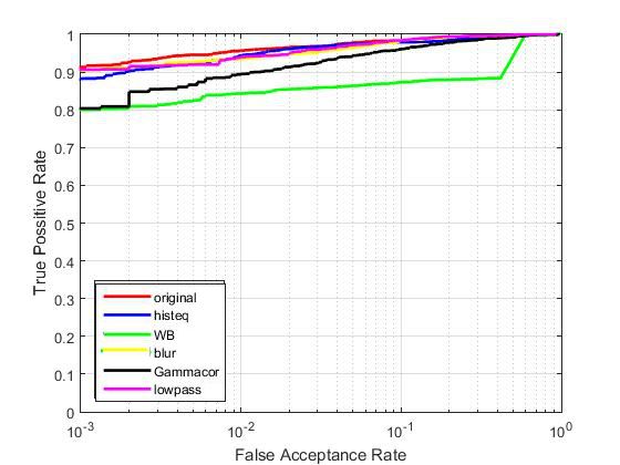
II. OVERVIEW OF CAMERA IDENTIFICATION                        neighborhood and they estimated interpolation coefficients
                                                                     through Singular Value Decomposition (SVD) for each region
   Camera identification is a well established research area. A      and each color band separately. Then, they reinterpolated the
variety of methods have been proposed, primarily exploiting          sampled CFA pattern and chose the one that minimizes the
the residual artifacts and imperfections in the imaging pipeline.    difference between the estimated final image and actual image
There are two separate camera identification methodologies           produced by the camera.
according to the information source they use. The first one
consists of methods which take advantage of existing sensor           III. C AMERA SENSOR IDENTIFICATION BASED ON PRNU
noise and artifacts in the CCD array [10]. The second one               The main artifact that is being used to estimate a sensor
approaches camera identification by employing demosaicking           fingerprint for each camera is the so called Photo-Response
artifacts taking place in raw image processing [11].                 Non-Uniformity (PRNU) [13]. Each pixel value generated
   There have three leading studies on camera identification         from either CCD or CMOS sensors slightly but consistently
based on sensor noise. Geradts et al. [12] observed that large       differs from its nominal value. This forms a specific pattern on
CCD arrays often contain a variety of manufacturing defects,         every image taken by this camera and is known to be unique
which, in total, amount to fixed pattern noise. In addition,         for every camera model. A camera fingerprint is generated
camera electronics generate random dark current [8]. They            by images known to have been taken by this camera. Once
have observed that, while dark current has limited potential         estimated, it can be tested whether it resides on an image and
in building a forensic signature, the fixed pattern noise of the     thus tell if it was taken using this specific camera.
CCD array is instrumental in constructing a unique camera               The estimation method of the PRNU fingerprint can be
fingerprint. Kurosawa et al. [10] and Lukas et al.[3] also tuned     seen in Figure 1. Analytic description of the PRNU estimation
their attention to the pattern noise of CCD arrays. It was found     model is given bellow.
that the systematic part of the noise does not change much
from image to image, it is relatively stable over camera life
                                                                                  Fig. 1. Estimation of the PRNU fingerprint
span and operating conditions and consists of the fixed pattern
noise plus Photo Response Non Uniformity noise (PRNU)
caused by the pixel non uniformities is a more persistent
camera feature [13]. The PRNU can be reliably extracted
by averaging the denoising residuals of several images [1]
resulting in an image pattern that plays the role of a camera
fingerprint. In this sense, camera identification has similarities
to image watermarking [14], the difference being that the
camera fingerprint is produced by the image sensors while the
watermark is primarily inserted by deliberate human action.
   Commercial image devices use a single mosaic structured
color filter array (CFA) rather than having separate filters            Let us assume that the output image will be denoted as I
for each color component. Camera models typically employ             and the image captured under the absence of any imperfections
propriety interpolation algorithms in recreating the missing         as I0 . The following sensor output model was established in
color values. The grid interpolation process, in turn, leaves        [3].
footprints, such as correlation patterns between contiguous bit
planes. Kharazzi et al. [4] tried to capture the differences in                             f = f0 + f0 K + v                     (1)
CFA configuration and color processing pipeline by a feature
based approach. They focused on image features, such as                 where K is the PNRU factor (fingerprint) and v includes
mean value of the RGB channels, correlations between color           all other components, such as dark current, shot noise, read-
components, differences in neighborhood probability distribu-        out noise and quantization noise. The fingerprint K can be
tion, wavelet domain statistics and image quality measures.          estimated from N images f1 , f2 , . . . , fN taken by the camera
Extensions of this work can be found in [15],[16]. Since the         and f0 K is understood element wise. The pixel intensity
residuals of interpolation algorithms depend on the nature of        of the i, j-th pixel in the kth image fk will be denoted
the captured content, these algorithms were fine tuned by            Iijk , 1 ≤ i ≤ k1 , 1 ≤ j ≤ k2 . Let W1 , W2 , . . . , WN be
separately treating the smooth and non smooth image regions.         the noise residuals obtained using a denoising filter F as
In another study, Long and Huang used interpixel correlations
originating from demosaicking camera fingerprinting [11].                          Wk = fk − F (fk ), k = 1, . . . , N            (2)
They defined a quadratic pixel correlation model and obtained
a coefficient matrix for each color band based on this model.           Assuming the following linearized sensor model for the
Swaminathan et al. [17] investigated the demosaicking artifacts      residual
using an analysis by synthesis method. They divided the
image into three regions based on gradient features in a local                      Wk = fk K + Ξk , k = 1, . . . , N             (3)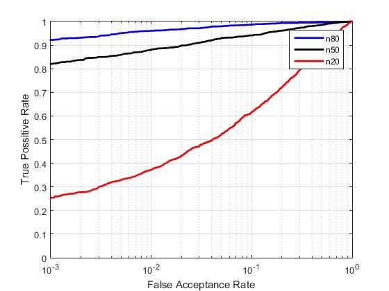
where Ξk is a n1 ×n2 matrix of independent and identically The case when H1 is rejected for an image that was captured
distributed (i.i.d.) Gaussian random variables with zero mean, from the original camera that is tested is called false rejection.
the maximum likelihood estimation of the PNRU multiplica- False acceptance means accepting H1 when the image was
tive factor K is given by : taken by another camera. We donote the false rejection rate
PN FRR and the false alarm rate FAR. The FRR is obtained from
k=1 fk Wk experiments and depends mainly on image quality and content
Kb = P
N
(4)
k=1 (fk )
and the number of images used to obtain the PRNU fingerprint
and their quality. Both FAR and FRR are functions of the
The detection of the fingerprint K in W can be formulated
detection threshold.
as a two channel hypothesis testing problem:
IV. E XPERIMENTAL RESULTS
H0 (non matching image) : K1 6= K2 In this section, we present the conducted experiments in
(5) order to evaluate the robustness of image processing manipu-
H1 (matching image) : K1 = K2 ,
lations (i.e., image filtering). To this end, we have employed
where: a publicly available camera cell phone identification dataset.
Detailed description of this dataset is found in IV-A. In
K
b 1 = K1 + Ξ1 subsection IV-C, we study the effect of different training
(6) set sizes employed to obtain the PRNU factor. Finally, in
W = IK2 + Ξ2 ,
subsection IV-D, we evaluate the performance of state-of-the
where the estimate of the camera fingerprint, K b 1 , is obtained art blind camera identification methods in manipulated images.
using (4), W is the noise residual and a Gaussian corrupting
noise Ξ1,2 ∼ N (µ, σΞ2 ). A good approximation to the gener- A. Evaluation Dataset
alized likelihood ratio test for the aforementioned hypothesis The employed dataset is the BUSIM cell phone database [2].
testing problem is the normalized correlation ρ(K b 1, Kb 2 ; 0, 0) This datasets consists of images captured from 16 models of
between K b 1 and Kb 2: different cell phone cameras. There are six brands among those
16 devices which are Motorola, Nokia, Samsung, Sony, Treo
P Palmone and LG. In fact, we have two Motorola models, five
i,j (Ui,j − U)(Vi+τ1 ,j+τ2 − V) Nokia, three Samsung, three Sony and one of Treo Palmone
ρ(U, V; τ1 , τ2 ) = qP qP
(U − U) 2 (V − V) 2 and LG models. The camera models are listed in Table I,.
i,j i,j i,j i+τ 1 ,j+τ 2
(7)
where the bar stands for the sample mean, vectors U and V TABLE I
M ODELS OF CAMERAS TESTED
could be any matrices like the fingerprint estimation K b and
the query fingerprint K, range of indices i, j, τ1 , τ2 in 7 is
LG 5600 Samsung D500
1 ≤ i, τ1 ≤ n1 , 1 ≤ j, τ2 ≤ n2 . Motorola V3 Samsung D600
Note that under H0 , we correlate two i.i.d. Gaussian signals Motorola V500 Samsung E720
since the fingerprint itself is well modeled by an i.i.d. Gaussian Nokia 5140 Sony K700
Nokia 6230 Sony K700
random variable. It can be established from the central limit Nokia 6600 Sony K750
1
theorem that in this case ρ(K1 , K2 ; 0, 0) ∼ N (0, N ). Thus, in
b b Nokia 6600 Sony P910
order to set a fixed threshold for the correlation that guarantees Nokia 7270 Treo Palmone
a prescribed√ false alarm of fingerprint detection, it must be
scaled by N :
The dataset consists of 200 images with each device, a total
√ of 3200 images, with a maximum resolution of 640 × 480 at
ρ(K, K;b 0, 0) → N ρ(K, K; b 0, 0) (8)
daylight, auto-focus mode and in JPEG format. The images
A frequently used detection statistic is the Peak Correlation were typical shots varying from nature scenes to closeup of
to Energy ratio (PCE) or signed (PCE) also referred to as the people. We have separated 100 of them in two groups so as
Circular Correlation Norm (CCN) defined as: to have a training and a testing set. For every experiment a
different set is created, with the exception of same type studies,
such as feature fusion (Figures 2 and 3), where the aim is
ρ2 (K, K;b 0, 0) × sign(ρ(K, K; b 0, 0))
P CE(K, K) =
b to examine the effect of a different approach on the same
1
P 2 (K, K;
n1 n2 −|Nmax | τ ,τ
1 2 ∈N
/ max
ρ b τ1 , τ2 ) data. The split of 1600 images used for training and testing
(9) happens each time independently making sure that there are
where Nmax is a small neighborhood around the origin and no duplicate images in both training and testing set.
|Nmax | is the number of elements in the neighborhood. Note
that the PCE can be viewed as another way to normalize the B. Feature fusion
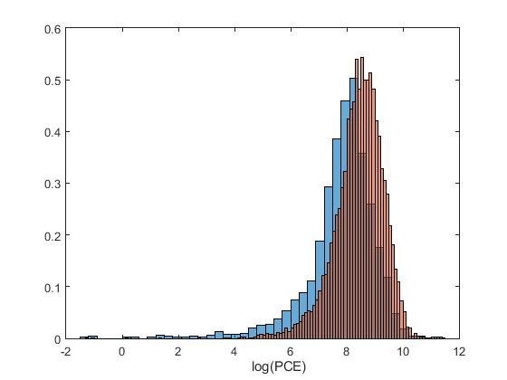
correlation - the denominator is an estimate of the correlation In our first set of experiments, we compare two late fusion
variance under the assumption that it has a zero mean. models for camera identification. The camera identification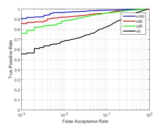
method proposed in Lukas et. al [3] suggests the use of pixel                 the known cameras. If the correlation is greater than a given
luminosities in the RBG channel, followed by a late fusion                    threshold t, the query image is classified to camera class with
approach. That is, we follow the denoinsing and the averaging                 the most similar PRNU pattern. Otherwise, it is considered
of the fingerprints with RGB to grayscale transform and work                  that the image was taken from another camera.
with their grayscale versions to compute the PCEs for H0 and                     In order to measure the similarity between the fingerprint
H1 . The results of this method are presented on Figure 2                     and the image query, we employ PCE metric. The PCE is a
where we have the histograms of the logarithm of the PCE                      more stable test statistic than correlation as it is independent
values on the left and their ROC curves on the right. Its clear               of the image size and has other advantages. We introduced on
from the ROC that the camera identification works fine with                   how PCE is obtained on ( 9) and we used Nmax to be a square
this method and we can find a threshold t where the overall                   region 11 × 11 around the peak where the maximum of the
accuracy will be higher than 95% with relatively small FAR                    normalized correlation exists. For each camera fingerprint we
rate.                                                                         evaluate PCE under H1 for the remaining matching images of
                                                                              the test set which will provide the data needed for estimating
  Fig. 2. Camera identification with RGB to grayscale late feature fusion     the FRR. Similarly we evaluate PCE under H0 for all the non-
                                                                              matching images of the test set to obtain the FAR. The PCE
                                                                              histograms for each hypothesis differ greatly in size. For H1
                                                                              we have a total of 1600 PCE values, while all the non matching
                                                                              cases of H0 produce 24000 PCE scores. Those numbers stand
                                                                              for every experiment that follows.
                                                                                 The sensor fingerprint is estimated with real content images
                                                                              rather than flat fields. Previous works propose flat fields for
                                                                              better results. To generate the reference pattern, a set of flat
                                                                              field images are first created by capturing between 20 and 50
   Furthermore, we explore a different feature fusion method,                 images of a uniformly lit surface using a known camera. For
which we have found that improves the accuracy of the                         example, out of focus images of a bright cloudy sky can be
classifier. That is, after the denoising and the averaging of                 used. However, experiments show that real content images can
the fingerprints, we concatenate each color channel one after                 perform as good as long as there are enough of them to draw
the other to create a vector of size 1440 × 640. This vector is               a better estimate. We have tested the performance for different
thereby employed to compute the PCE for H0 and H1 . The                       training set size that range from n = 5 to n = 100 images.
results of this late fusion method are shown on Figure 3.                     The collective ROC curves for each set are depicted in Figure
                                                                              4.
Fig. 3. Camera identification with concatenated color channels late feature
fusion
                                                                                Fig. 4. Different number of training image sets and their ROC curves

C. Number of images used to obtain PRNU factor
   In our second set of experiments, we study the effect of
different number of images used to obtain the PRNU factor.
In order to generate the reference pattern, we employ the                        As can be seen, when real content images are employed
denoised training set. To this end, we employed the same                      instead of flat fields, values of n = 20 or n = 50 are not
Wavelet-based denoising filter by Mihkac et al. [18], that                    enough to provide a good estimation of the PRNU factor.
Lucas et al.[3] proposed in their initial presentation of the                 Instead, values of n = 100 should be employed. When the
sensor fingerprint method. The PRNU pattern estimate is                       content of the images is not flat field then a greater number
found by averaging the noise residuals of the training set.                   of images is required to achieve better results and higher
Once the reference pattern has been determined, it can be                     accuracies.
used to identify whether the camera used to generate the
reference pattern was also used to capture a given query                      D. Camera classification under image manipulations
image. The noise residual of the query image is obtained                        Finally, we study the effects of image manipulations in
and correlated with the reference PRNU pattern of each of                     camera classification. There are instances where the images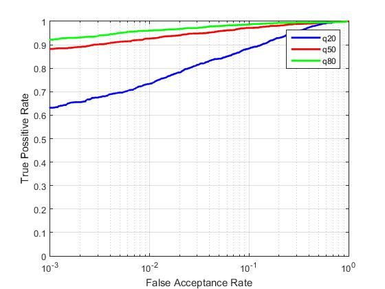
presented to a camera identifier are manipulated with mali- Fig. 6. ROC curve of the ”malicious” image manipulations scenario, i.e.,
cious or innocent intent. We have subjected our images under only the test set have gone under image processing manipulations.
the effects of low pass filter, contrast enhancement, histogram
equalization, gamma correction and white balance. Note that
we have not gone too far with the manipulations and every
attack is a subtle one (3 × 3 filters, small gamma correction
factors, etc.). We aim to produce results that can relate to real
life scenarios where either the attacker has a malicious intent
and wants to counterfeit an original photo or he simply puts
every image he captures under a desired filter for improving
the content of his image.
Some cases of manipulations such as histogram equalization
and white balance are applied with the same effect on all
images. While, the cases of low pass Gaussian and blur filter
as well as gamma correction have varying parameters on all
images. Such as 3 × 3 and 5 × 5 filters changing randomly important factor in determining the robustness of fingerprint,
for blur and low pass Gaussian, and gamma correction factor since performance of fingerprint extraction algorithm degrades
varying from γ ∈ [1.5, 3]. due to compression. We have subjected our images under the
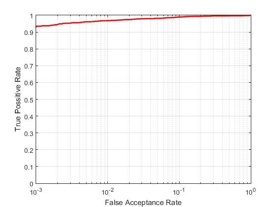
We have conducted two classification experiments according effects of JPEG compression with varying quality factors.
to the aforementioned scenarios. In the first experiment, we The quality factor of the JPEG algorithm is instrumental
have put both the training set and the testing set under in the accuracy of the camera identification algorithm. We
the effect of the same manipulations. That is, we employed have produced results with three different values of quality,
n = 100 training images for each camera. This is the scenario q = 20, 50, 80. Quality factor values close to 100 mean almost
were we assume that all images might be subject of prior no effect to the original image. The same factor is applied
manipulation, e.g., low-pass filter. The results for every filter throughout all images.
are presented collectively with their ROC curves on Figure 5. Once again, two classification experiments are conducted.
First, both the training and testing set are under the effects of
Fig. 5. ROC curve of the ”innocent” image manipulations scenario, i.e., JPEG compression. The collective results of this scenario for
both the training set and the testing set are under the effect of the same three different quality factor values are presented on Figure
manipulations. 7.
Fig. 7. ROC of JPEG compression on both sets
In our second scenario, the training set is not manipulated
with any filter. However, we assume that only the test set
have gone under image processing manipulations. This is the
scenario that relates to the malicious intent. The collective
results of this scenario are shown on Figure 6. In the second scenario, the training set does not go under
As can be seen, prior image manipulation of the training set JPEG compression, having only the training set under the
does not affect the performance of camera de-identification. In alteration. The results of this experiment are shown on Figure
all cases, the most effective filter for camera de-identification 8.
is the White Balance filter as well as the low pass and blur It can be seen that JPEG compression can affect the iden-
filters but this is mainly because of the 5 × 5 filters which are tification algorithm especially when the quality factor is low
known to leave a visual impact on the image. and the compression algorithm is used on both the images that
were used for the camera fingerprint estimation as well as the
E. Camera classification under JPEG compression query image. However, we should also note that when JPEG
Cell phone images can be highly compressed, hence the compression quality factor q = 20 is employed, the resulting
effect of compression is studied. JPEG compression is an image is visibly altered.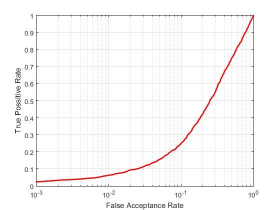
Fig. 8. ROC of JPEG compression on both sets                     [2] O. Çeliktutan, B. Sankur, and I. Avcibas, “Blind identification of source
                                                                                  cell-phone model,” IEEE Transactions on Information Forensics and
                                                                                  Security, vol. 3, no. 3, pp. 553–566, 2008.
                                                                              [3] J. F. J. Lucas and M. Goljan, “Digital camera identification from sensor
                                                                                  noise,” IEEE Transactions on Information Security and Forensics, vol. 1,
                                                                                  no. 2, pp. 205–214, 2006.
                                                                              [4] M. Kharrazi, H. T. Sencar, and N. Memon, “Blind source camera
                                                                                  identification,” in Image Processing, 2004. ICIP’04. 2004 International
                                                                                  Conference on, vol. 1. IEEE, 2004, pp. 709–712.
                                                                              [5] M. Goljan and J. Fridrich, “Camera identification from scaled and
                                                                                  cropped images,” Security, Forensics, Steganography, and Watermarking
                                                                                  of Multimedia Contents X, vol. 6819, p. 68190E, 2008.
                                                                              [6] M. Goljan, J. Fridrich, and M. Chen, “Defending against fingerprint-
                                                                                  copy attack in sensor-based camera identification,” Information Foren-
                                                                                  sics and Security, IEEE Transactions on, vol. 6, no. 1, pp. 227–236,
                                                                                  2011.
                                                                              [7] M. Goljan and J. Fridrich, “Sensor fingerprint digests for fast camera
                                                                                  identification from geometrically distorted images,” in IS&T/SPIE Elec-
F. Camera de-identification by fingerprint removal                                tronic Imaging. International Society for Optics and Photonics, 2013,
                                                                                  pp. 86 650B–86 650B.
   Finally, we investigate the scenario where the malicious user              [8] I. Pitas, Digital image processing algorithms and applications. John
intents to employ the PRNU factor from a set of images of                         Wiley & Sons, 2000.
his own camera, and employ post-processing to remove it. In                   [9] M. C. M. Goljan and P. Comesana, “Effect of compression on sensor-
                                                                                  fingerprint based camera identification,” IS&T, Electronic Imaging, Me-
this scenario, we have created a training set of n = 100 real                     dia Watermarking Security, and Forensics, 2016.
life images and estimated the PRNU factor for every camera                   [10] K. Kurosawa, K. Kuroki, and N. Saitoh, “Ccd fingerprint method-
model. Afterwards, the estimated PRNU factor is subtracted                        identification of a video camera from videotaped images,” in Image
                                                                                  Processing, 1999. ICIP 99. Proceedings. 1999 International Conference
from the test set. Experimental results are shown in Figure                       on, vol. 3. IEEE, 1999, pp. 537–540.
9. As can be seen, effective camera de-identification can be                 [11] Y. Long and Y. Huang, “Image based source camera identification
obtained, which should be alarming to forensics investigators.                    using demosaicking,” in 2006 IEEE Workshop on Multimedia Signal
                                                                                  Processing, 2006.
                                                                             [12] Z. J. Geradts, J. Bijhold, M. Kieft, K. Kurosawa, K. Kuroki, and
                                                                                  N. Saitoh, “Methods for identification of images acquired with digital
Fig. 9. Camera identification with fingerprint removed from testing images
                                                                                  cameras,” in Enabling Technologies for Law Enforcement. International
                                                                                  Society for Optics and Photonics, 2001, pp. 505–512.
                                                                             [13] M. Chen, J. Fridrich, M. Goljan, and J. Lukáš, “Source digital camcorder
                                                                                  identification using sensor photo response non-uniformity,” in Electronic
                                                                                  Imaging 2007. International Society for Optics and Photonics, 2007,
                                                                                  pp. 65 051G–65 051G.
                                                                             [14] N. Nikolaidis and I. Pitas, “Robust image watermarking in the spatial
                                                                                  domain,” Signal processing, vol. 66, no. 3, pp. 385–403, 1998.
                                                                             [15] S. Bayram, İ. Avcıbaş, B. Sankur, and N. Memon, “Image manipulation
                                                                                  detection,” Journal of Electronic Imaging, vol. 15, no. 4, pp. 041 102–
                                                                                  041 102, 2006.
                                                                             [16] S. Bayram, H. T. Sencar, N. Memon, and I. Avcibas, “Improvements on
                                                                                  source camera-model identification based on cfa interpolation,” Proc. of
                          V. C ONCLUSION                                          WG, vol. 11, pp. 24–27, 2006.
                                                                             [17] A. Swaminathan, M. Wu, and K. Liu, “Nonintrusive component foren-
   In this paper, we have presented a detailed study on camera                    sics of visual sensors using output images,” Information Forensics and
identification, on images manipulated by standard image pro-                      Security, IEEE Transactions on, vol. 2, no. 1, pp. 91–106, 2007.
                                                                             [18] K. I. Mihcak M.K. and R. K., “Spatially adaptive statistical modeling
cessing application. Experimental results have shown that the                     of wavelet image coefficients and its application to denoising,” IEEE
camera identification is still possible when specific filtering ap-               International Conference on Acoustics, Speech, and Signal Processing
plications have been applied. However, legal authorities should                   (ICASPP), vol. 6.
be alarmed when advanced PRNU related manipulations have
been applied, which is not visible to the human eye. Future
work could include further evaluation in larger datasets, as
well as more detailed experimental analysis.
                        ACKNOWLEDGMENT
   The research leading to these results has received funding
from the European Union Seventh Framework Programme
(FP7/2007-2013) under grant agreement number 316564 (IM-
PART) and grant agreement number 287674 (3DTVS).
                            R EFERENCES
 [1] T. M. Goljan and J. Fridrich, “Large scale test of sensor fingerprint
     camera identification,” Electronic Imaging, Media Forensics and Secu-
     rity (SPIE), vol. 12.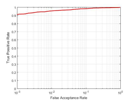

You can also read