Look at my new blue force-sensing shoes! - arXiv.org
←
→
Page content transcription
If your browser does not render page correctly, please read the page content below
Look at my new blue force-sensing shoes!
                                                                            Yuanfeng Han∗ , Ruixin Li∗ and Gregory S. Chirikjian†,∗

                                            Abstract— To function autonomously in the physical world,
                                         humanoid robots need high-fidelity sensing systems, especially
                                         for forces that cannot be easily modeled. Modeling forces in
                                         robot feet is particularly challenging due to static indetermi-
                                         nacy, thereby requiring direct sensing. Unfortunately, resolving
                                         forces in the feet of some smaller-sized humanoids is limited
arXiv:2104.06618v1 [cs.RO] 14 Apr 2021

                                         both by the quality of sensors and the current algorithms
                                         used to interpret the data. This paper presents light-weight,
                                         low-cost and open-source force-sensing shoes to improve force
                                         measurement for popular smaller-sized humanoid robots, and
                                         a method for calibrating the shoes. The shoes measure center of
                                         pressure (CoP) and normal ground reaction force (GRF). The
                                         calibration method enables each individual shoe to reach high
                                         measurement precision by applying known forces at different                   Fig. 1.   A Nao robot wears a pair of new force-sensing shoes.
                                         locations of the shoe and using a regularized least squares
                                         optimization to interpret sensor outputs. A NAOTM robot is
                                         used as our experimental platform. Experiments are conducted
                                         to compare the measurement performance between the shoes                  measurement precision. However, six-axis F/T sensors are
                                         and the robot’s factory-installed force-sensing resistors (FSRs),         generally expensive and heavy – the added weight increases
                                         and to evaluate the calibration method over these two sensing             the moment of inertia of the foot and decreases the dynamic
                                         modules. Experimental results show that the shoes significantly           postural stability [10]. Therefore, six-axis F/T sensors have
                                         improve CoP and GRF measurement precision compared to
                                         the robot’s built-in FSRs. Moreover, the developed calibration            limited applications in the context of smaller-sized humanoid
                                         method improves the measurement performance for both our                  platforms. Another common type of foot sensors are thin-
                                         shoes and the built-in FSRs.                                              film FSRs: these are usually installed on relatively smaller
                                                                                                                   humanoid platforms, such as the NAOTM (subsequently
                                                                 I. I NTRODUCTION                                  this is referred to as Nao) [11] and the H7 robot [12].
                                            Foot force sensors are widely used in humanoid robots                  Despite their light-weight nature, FSRs generally have lower
                                         for measuring GRFs and CoPs, which quantify the stability                 measurement precision and repeatability compared to strain-
                                         status of the system [1]. Many researchers and developers                 gauge type sensors. Therefore, without effective calibration
                                         design planning and control algorithms for humanoid robots                methods, it is difficult to use such sensors for estimating
                                         according to their foot sensory feedback in the studies of                accurate CoP location in the feet of humanoid robots.
                                         dynamic walking [2], self-balancing [3], push-and-recovery                   The performance of force sensors can be affected by
                                         [4], etc. Additionally, many state estimation problems such               various factors. For example, changes in the ambient temper-
                                         as estimating center of mass (CoM) location [5] and external              ature affects the physical properties of the strain gauge [13]
                                         forces [6] in the dynamic motion of the humanoid robot                    and the resistance coefficient of the FSRs [14], causing the
                                         require the integration of foot force data together with other            sensor to drift. Moreover, slight variations in the mechanical
                                         in-body sensory data like an encoder or an IMU. Recent                    structure during usage, such as changes in screw tension and
                                         studies also show that high-precision foot force sensors can              deformations of the mounting material, may also produce
                                         be used to identify the inertial properties of heavy objects              drift or alter sensor output. Therefore, an effective calibration
                                         for humanoid robot manipulation tasks [7].                                method is critical for improving measurement precision of
                                            Two major types of force sensors are commonly used in                  foot force-sensing modules.
                                         measuring CoPs and GRFs for humanoid robots. Commercial                      There exist several studies focusing on developing foot
                                         six-axis force/torque (F/T) sensors have been applied for                 force-sensing modules for CoP and GRF measurements for
                                         many larger-sized humanoid platforms [8], [9]. This type                  smaller-sized humanoid robots. Shayan et al. presented a
                                         of sensor utilizes a strain gauge mechanism, which outputs                modular shoe design for the Nao using barometric sensors
                                         a linear response to the external force and possesses high                [15]. Almeida et al. proposed a force-sensing shoe design
                                          ∗ Yuanfeng Han and Ruixin Li are with the Department of                  using two separate layers for the Nao [16]. Kwon et al [17]
                                         Mechanical Engineering, Johns Hopkins University, Baltimore, MD.          developed a pressure-sensing foot using custom-fabricated
                                         yhan33@jhu.edu                                                            polymer-based film for a KIBO robot. Suwanratchatamanee
                                           †,∗ Gregory S. Chirikjian is with the Department of Mechanical Engi-
                                                                                                                   et al [18] developed haptic-sensing feet with three sensing
                                         neering, National University of Singapore, Singapore and the Department
                                         of Mechanical Engineering, Johns Hopkins University, Baltimore, MD.       layers for a KHR-2HV robot. The previously developed
                                         mpegre@nus.edu.sg, gchirik1@jhu.edu                                       foot-sensing modules can theoretically improve measurement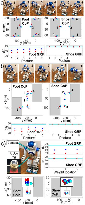
TABLE I
Foot Light Low Off-the-shelf 3D wireless open
module weight cost component printable source
Nao Pressure[15] 3 3 7 3 3 7
Nao ITShoe[16] 3 3 3 7 3 7
H7 Matrix FSR[12] 3 — 7 7 7 7
KIBO Foot[17] 3 — 7 7 7 7
KHR-2HV Foot[18] 3 — 7 7 7 7
Our Shoe 3 3 3 3 3 3
— property is not is introduced in the literature
precision with their high-quality sensors. However, a detailed
calibration technique is necessary to further optimize their
sensing performance and evaluation experiments are needed
to quantify the sensing precision of these modules.
This paper presents a pair of low-cost, light-weight and
open-source force-sensing shoes for smaller-sized humanoid
robots (Fig. 1). The new shoes have many advantages
over the above-mentioned existing foot-sensing modules (see
Table I). A calibration method is proposed, which utilizes
regularized least-squares to minimize the error between the
measured and the reference CoPs and GRFs using our
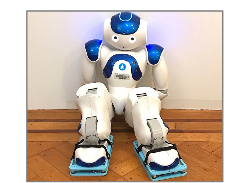
3-D printed calibration apparatus. The calibration enables Fig. 2. a) Nao’s foot design. b) Sensing area of the foot. c) Shoe schematics.
the shoes to reach high measurement precision. For each d) Shoe’s electronic components.
calibrated shoe, the CoP mean absolute error is less than 2
mm and the GRF mean absolute error is less than 0.025 N.
Three validation experiments are implemented on both the commercially. Other options such as soft-matter based sen-
Nao’s factory-installed FSRs in its feet and our new shoes. sors and optical sensors are also considered in the sensor
The results show that the shoes possess a significantly higher selection process. However, soft-matter based sensors are
measurement precision compared to the built-in FSRs of the often susceptible to hysteresis, which limits their accuracy
Nao; The developed foot-sensor calibration method improves when measuring rapidly or cyclically changing forces [19];
the CoP and GRF measurement precision for both the built- Relatively accurate optical-based force sensors can be costly
in FSRs and the force-sensing shoes. and often require complex setups [20]. Here, the working
II. NAO ’ S FOOT AND FORCE - SENSING SHOE range of our selected load cells are 0 - 50 N. The dimensions
of the assembled shoes are 170mm × 95mm × 21mm. Each
The CoP and GRF sensing performances are compared
shoe weighs 135g – only 2.4% of the mass of the Nao.
between the Nao’s factory-installed FSRs in its feet and our
The overall component cost of each shoe is less than 30 US
new force-sensing shoes.
dollars. The shoe is fully open source and the details are in
A. Nao’s foot https://github.com/yhan33/Force-sensing-shoes-for-Nao. Our
Each foot of the Nao contains four FSRs (Fig. 2a), of force-sensing shoes possess many advantages over the exist-
which the working range are 0 - 25 N. These FSRs form an ing foot force-sensing modules introduced in section I, which
approximate 100 × 53 mm rectangular sensing area (Fig. 2b) are shown in Table I.
(referred to as foot sensing area), which defines the stable 1) Mechanical Design: Each shoe works similarly like
region of the CoP inside each foot. The bottom of the foot a force plate. The shoes are comprised of two 3-D printed
is covered by a rigid plate, which connects to the top foot plates. The upper plate has an indentation which tightly fits
via screws (Fig. 2a). The CoP and GRF measurements of the the Nao’s foot (Fig. 2c, top view). The electronic components
foot rely on the deformation of the bottom plate to deliver are mounted to the bottom plate and sit under the upper plate
force to each FSR. However, the measurement is unreliable (Fig. 2c, d). For each load cell, its one side is cantilevered
since the bottom foot plate barely deforms and it is unlikely from the pillar on the bottom plate and the tip of the other
that the four FSRs will activate at the same time. side connects to the top plate via a screw (Fig. 2c, side view).
The top plate is designed much thinner and more flexible
B. Force-sensing shoe compared to the thick and rigid bottom plate. This design
A pair of force-sensing shoes are developed for smaller- ensures that all four load cells engage simultaneously when
sized humanoid robots. Single-axis load cells are chosen the robot puts weight on the shoes. Since the whole bottom
to construct the shoes due to their high-accuracy, linear- plate contacts with the ground, the shoe can also be used for
response and low-drift. In addition, small-size, light-weight measuring forces on uneven terrain. In contrast, in designs
and low-cost single-axis load cells are readily available in which four rigid load cells are directly on the flat floor,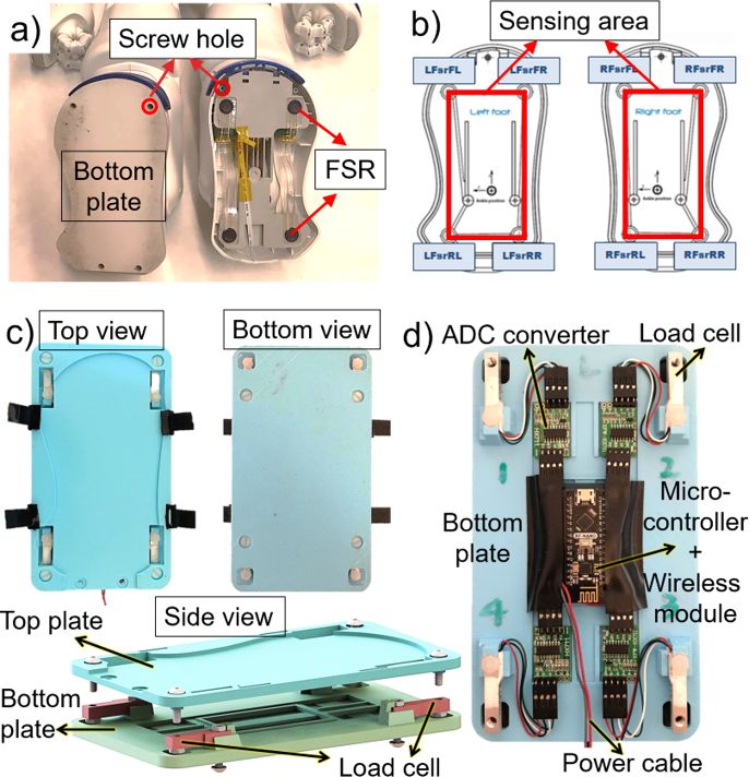
it is very likely that one of them may lose contact due to        and internal deformations or stresses after assembly. There-
manufacturing or assembly misalignment. In addition, such         fore, it is necessary to calibrate the sensor parameters for
design can hardly adapt to uneven terrain since sensors may       both feet and shoes to enable optimal measurement precision.
lose contact if the middle area of the shoe is lifted up by          The calibration apparatus is shown in Fig. 3, top. A 3D-
obstacles. The shoes are designed with straps to facilitate       printed sole plate is attached to the foot or the shoe. The
easy removal. In practice, they can be screwed or glued on        sole plate has a 3 by 6 array of cylindrical protrusions
the foot of the robot for common usage.                           designed to support a variable weight. The exact location
   2) Data transmission: All electronic components in the         of each protrusion relative to the foot’s or shoe’s body
force-sensing shoes are chosen off-the-shelf (Fig. 2d). The       frame is pre-recorded, and are used to obtain the reference
shoes can be powered by external batteries. Raw data from         CoP location. Since the whole calibration apparatus is static
the load cells first passes through the corresponding Analog-     during calibration process, the reference CoP can be obtained
to-Digital Converters, which is then transmitted wirelessly       by projecting the CoM of the calibration apparatus onto
by a micro-controller. A sister module receives the data and      the x-y flush with foot or the shoe. The reference GRF is
transfers it to a PC via USB serial communication. The            simply the gravitational force of the calibration apparatus.
communication frequency between the shoes and the PC can          Denoting the reference CoP location as [Cx , Cy ]T ∈ R2 and
reach up to 80 Hz.                                                the reference GRF as N, they are given by:
                                                                                                                s
                                                                                                       p          p
            III. F OOT AND SHOE CALIBRATION                                   (Gweight + Gcap ) x + Gsole xs
                                                                             Cx                        py         py
   The calibration algorithm developed here is tested both on                    =                                    ,      (2)
                                                                             Cy           Gweight + Gcap + Gsole
the Nao’s built-in FSRs and on our force-sensing shoes.
                                                                                       N = Gweight + Gcap + Gsole ,                       (3)
A. Measurement principle
                                                                  where Gweight , Gcap , Gsole are the weight of the calibration
  Both the Nao’s foot and the shoe incorporate four individ-
                                                                  weight, the supporting cap and the sole plate1 (Fig. 3b,
ual sensors’ data to obtain the CoP and GRF measurement.
                                                                  top, right) and [px , py ]T is the reference CoP location of
We denote each sensor’s force output as Fi and its location
                                                                  the weight and supporting cap together, which is the center
in x-y plane as seen from the local frame attached to the
                                                                  of the protrusion used in the measurement. Here, [psx , psy ]T
foot or the shoe as pi ∈ R2 (i = 1, . . . , 4). The measured
                                                                  are the CoM of the sole plate, which is obtained from its
GRF value and CoP location for each foot or shoe are given
                                                                  CAD model. The calibration algorithm aims to update sensor
by ∑i Fi and ∑i Fi pi / ∑i Fi , respectively. The CoP and GRF
                                                                  parameters to enable optimal measurement precision. Here,
measurements for double support can be obtained by simply
                                                                  the raw sensor output of each FSR and load cell is denoted as
summing over all eight sensors.
                                                                  S, and the corresponding updated force output F is modeled
B. FSR and load cell force output                                 using an 1-D affine transformation such that F = cS + d.
                                                                  Denoting the measured CoP location in the x, y directions as
   1) Nao’s foot FSR: The factory installed FSRs are cal-         [cx , cy ]T and the measured GRF as n, the measured values
ibrated before assembly such that their raw sensor outputs        are given by:
directly indicate the forces applied to the sensors.                                         k                      k
   2) Single load cell: Each load cell is calibrated to convert                      4       tx       4                t
                                                                              ∑k=1 (Fk k ) ∑k=1 (ck S + dk ) xk
raw sensor output to physical force. Here, we denote the                     cx              t y                       ty
                                                                                 =      4
                                                                                                  =     4
                                                                                                                          ,  (4)
loaded raw sensor reading as S, the average unloaded reading                 cy        ∑n=1 Fk         ∑k=1 (ck S + dk )
as a, the scaling factor as b, and the force measurement as F.
The mapping between raw sensor reading and force output                                      4          4
can be described using an affine transformation:                                       n=   ∑ Fk = ∑ (ck S + dk ),                        (5)
                                                                                            k=1        k=1
                    (S − a) S a                                    (see III-A), in which k represents the designated sensor and
               F=          = − = cS + d,                    (1)
                       b    b b                                   [tx ,ty ]T indicate the location of the sensor’s measuring point
in which c and d are the modified scaling factor and offset.      in the x-y coordinate of the frame of the foot or the shoe.
The offset a is obtained by recording the average no-load             A least-squares regression is used to minimize the differ-
reading of the sensor. The scaling factor b is computed           ence between the reference CoP and GRF and their measured
by first placing a known weight on the sensor and then            values. To prevent overfitting, an extra regulation term is
dividing the change in each sensor’s output by the weight’s       applied to penalize the difference between the updated force
gravitational force.                                              output and the initial force output. Specifically, the updated
                                                                  affine model parameters of the load cell are bounded around
C. Foot and Shoe calibration method                               the initial calibrated parameters (see III-B) and the updated
  The Nao’s foot does not deliver accurate CoP and GRF            FSR force output is bounded around the raw force output.
measurements (see II-A). Similarly, the shoe’s measurement          1 For the Nao’s foot, experiments show that the weight of its bottom plate
precision is likely to drop due to mechanical misalignment        does not impact the sensor outputs when the foot is upside down.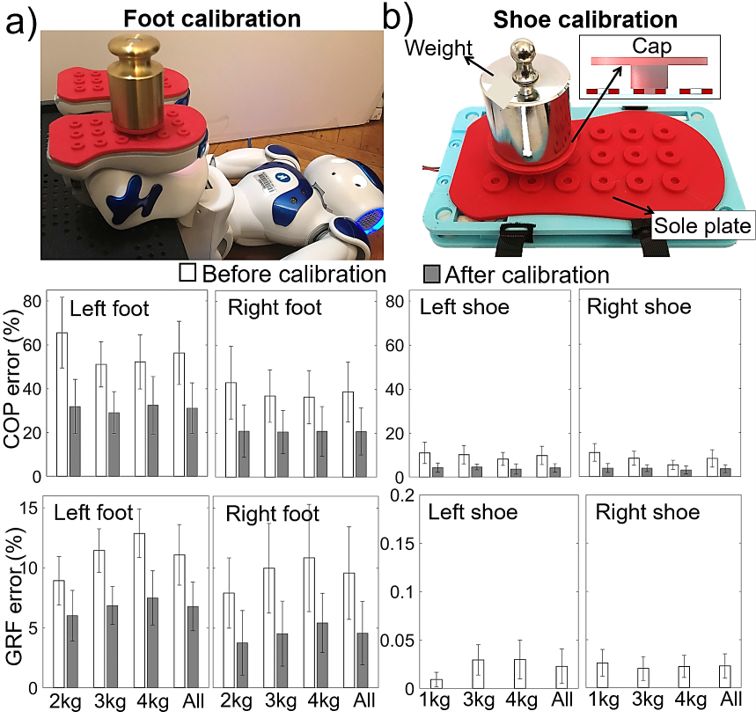
GRF error is set to 0 for the shoe’s calibration.
                                                                               D. Performance evaluation
                                                                                  To ensure our calibration covers a broad sensing range,
                                                                               1 kg, 2 kg and 4 kg weights (≈ 18%, 36% and 74% of the
                                                                               robot’s mass) are placed on each protrusion in the 3×6 array
                                                                               (Fig. 3b) for the shoe’s calibration; 2 kg, 3 kg (55% of the
                                                                               robot’s mass) and 4 kg weights are placed on the middle
                                                                               three rows of the protrusions for the foot’s calibration2 . The
                                                                               manual calibrations of the foot and the shoe comprise 36 and
                                                                               54 different combinations of weights and positions.
                                                                                  Two relative error metrics, eC and eG , are designed to
                                                                               quantify the precision of the CoP and GRF measurements:
                                                                                                     π(||Cx − cx ||2 + ||Cy − cy ||2 )
                                                                                              eC =                                     ,          (7)
                                                                                                                    A
                                                                                                               ||N − n||
                                                                                                         eG = 4           ,                       (8)
                                                                                                              ∑i=1 G f sr
                                                                               where A is the area of the support polygon and G f sr is the
                                                                               sensing range of each FSR. Here, eC expresses the distance
Fig. 3. a) Foot calibration. b) Shoe calibration. Middle row shows the         between the reference and measured CoP, relative to the
CoP relative measurement error of the left and right foot/shoe. Bottom row     radius of a circle whose area is equivalent to that of the foot
shows the GRF relative measurement error of the left and right foot/shoe.
The empty and filled bars show the error before and after calibrations.        sensing area, and eG represents the absolute GRF error over
The GRF measurement is not calibrated for the Shoe. Note that scales are       the total sensing range of one foot. For comparison purpose,
different so as to accurately display data.                                    the denominators of the error metrics of the shoe are the
                              TABLE II
                                                                               same as those of the foot.
                  M EAN ABSOLUTE MEASUREMENT ERROR
                                                                                  The error metrics corresponding to each chosen weight
                                                                               averaged over different locations in the calibration array and
                   CoP MAE      CoP MAE       GRF MAE       GRF MAE            the error metrics overall the weights and locations of the left
                     (mm)         (mm)           (N)          (N)
                                                                               and right feet and the left and right shoes are shown in Fig.
    Calibration       NO           YES           NO           YES
     Left Foot       23.13        12.81         10.85         6.65             3. The overall errors for both CoP and GRF (only for foot)
    Right Foot       15.95         8.56          9.39         4.48             are reduced after calibrations (Fig. 3, filled bar) and remain
    Left Shoe         4.07         1.76         0.023         N/A              relatively stable across different weights, suggesting that the
    Right Shoe        3.41         1.51         0.022         N/A
                                                                               optimized parameters produce accurate measurements over
                                                                               a wide range of forces. In addition, the force-sensing shoes
                                                                               show significant higher precision compared to the feet of the
  Since the FSRs exhibit poor CoP and GRF measurement
                                                                               Nao both before and after calibrations.
performance (Fig. 3, left, empty bars), the optimization is
                                                                                  The mean absolute error (MAE) of the feet and the shoes
designed to minimize both CoP and GRF error over the space
                                                                               are also shown in TABLE II. The CoP and GRF MAE
of 1-D affine transformations. The regularized least square
                                                                               are defined by the averaged Euclidean distance between the
problem is formulated as:
                                                                             measured and the reference CoPs and the averaged absolute
         argmin J = kCx − cx k2 + Cy − cy
                                             2
                                                        (6)                    difference between the measured and reference GRFs. For
               ζ                                             wc                each shoe, the MAE of CoP (after performing calibration) is
                             + kN − nk2wn    + kζ   − ζ0 k2wζ   ,              less than 2 mm and the MAE of GRF is less than 0.025N.
                                                                                                       IV. E XPERIMENTS
in which optimization variables ζ = [c1 , . . . , c4 , d1 , . . . , d4 ]. ζ0
represent the FSRs’ initial force outputs. Cx , Cy , cx , cy , N, n               A Nao robot is used as our testing platform. Experiments
are vectors corresponding to the measured and reference                        are designed to evaluate the precision of CoP and GRF
CoP and GRF across all different calibrating locations and                     measurements using error metrics defined in III-D by the
weights. Here, wc , wn , wξ are the weights associated with                    Nao’s built-in FSRs and the shoes using two force readings:
each set of terms.                                                             1. the raw sensor force readings without calibration (see III-
   Compared with the FSRs, the shoes’ GRF measurement                          B); 2. the updated force readings after calibration (see III-C).
is very precise (Fig. 3b, bottom, empty bars). Therefore, the                  The experiments are performed using several pregenerated
shoe’s GRF measurement can be obtained directly from the                       double support configurations of the robot and the measured
initial calibration parameters of the load cells ζ0 (see III-                  results are eventually compared with the reference results
B) and the updated parameters ζ are used only for CoP                             2 Some FSRs do not respond to 1 kg weight in our experiment and only
measurement. Therefore, the weight term wn for minimizing                      three middle rows are within the sensing area confined by the FSRs.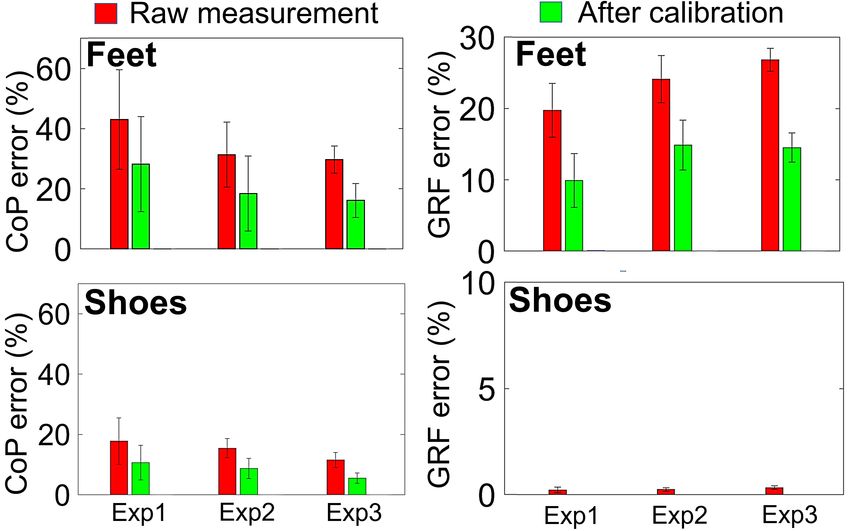
Fig. 5. CoP and GRF relative errors of three evaluation experiments. The
                                                                              CoP (left) and GRF (right) of the Nao’s feet (top) and the shoes (bottom).
                                                                              Red and green show results with and without calibration. Scales are different
                                                                              so as to accurately display data.

                                                                              (see section V). The experiments are explained as follows:
                                                                              1. Edge and center test. The CoP and GRF are measured
                                                                              using six different generated postures in a fixed double
                                                                              support. The CoPs of these postures are distributed in dif-
                                                                              ferent locations in the support polygon (Fig. 4a). Four of
                                                                              the postures are near the edge of the support polygon (Fig.
                                                                              4a, 3 - 6) and two are close to the middle (Fig. 4a, 1, 2).
                                                                              In the experiment, robot remains static in a posture for 8
                                                                              seconds while sensing data is recorded and then averaged
                                                                              and evaluated. Fig. 4a shows one set of experimental data of
                                                                              CoP (middle) and GRF (bottom) measurement for the feet
                                                                              (left) and the shoes (right).
                                                                              2. Changed double support test. The CoP and GRF
                                                                              measurements are tested in five postures (Fig. 4b, 1-5) in a
                                                                              very different double support compared to the one designed
                                                                              in the previous experiment (Fig. 4a): the robot moves its
                                                                              right foot 70 mm to the front (close to the robot’s maximum
                                                                              step length). The testing details are the same as the first
                                                                              experiment and one set of result is shown in Fig. 4b.
                                                                              3. External weight test. To evaluate foot sensing perfor-
                                                                              mance reacting to external forces, an external 1 kg weight
                                                                              with an attached ArUco tag [21] is placed at three random
                                                                              locations on the robot’s arms within the detection range of
                                                                              the robot’s camera (Fig. 4c, top-left). The testing details are
                                                                              the same as the previous experiments and one set of result
                                                                              is shown in Fig. 4c.
                                                                                 For comparison purpose, both the feet and the shoes are
                                                                              tested using the same double support configurations. The
                                                                              grey areas in Fig. 4 are the sensing areas of the feet (see
Fig. 4. Evaluation experiments. a, b top show designed configurations and c   Fig. 2b). Each of the three experiments described above is
top-left shows one demo of the weight experiment. a, b middle and c, bottom   performed on three separate days for the Nao’s feet, and
show CoP measurement of the feet (left) and shoes (right). a, b bottom and
c top-right show GRF measurements. Teal, red and blue show the reference      on three separate days for the shoes (the shoes are not
value, measurement value without calibration and with calibration. Circle,    detached during the shoes’ experiments). The calibration is
square and triangle in c represent different weight placements.               only performed for the first day and the updated parameters
                                                                              are used for the experiments on the following two days. The
                                                                              averaged results of each individual experiment are used for
                                                                              measurement performance evaluation.
V. R ESULTS [2] S. Tsuichihara, M. Koeda, S. Sugiyama, and T. Yoshikawa, “A sliding
walk method for humanoid robots using zmp feedback control,” in
To evaluate the measurement performance, the reference 2011 IEEE International Conference on Robotics and Biomimetics.
CoP and GRF corresponding to each measured result is IEEE, 2011, pp. 275–280.
required. Since the inertial properties of the Nao is fully [3] S. Nakaura, M. Sampei et al., “Balance control analysis of humanoid
robot based on zmp feedback control,” in IEEE/RSJ International
provided by its company, which showed descent accuracy Conference on Intelligent Robots and Systems, vol. 3. IEEE, 2002,
in our previous work [7], here we use modeled CoP and pp. 2437–2442.
GRF as references: when the robot stands statically, its [4] P. Ghassemi, M. T. Masouleh, and A. Kalhor, “Push recovery for nao
humanoid robot,” in 2014 Second RSI/ISM International Conference
reference CoP can be obtained using the projection of its on Robotics and Mechatronics (ICRoM). IEEE, 2014, pp. 035–040.
CoM on the ground. In practice, the CoM of the robot is [5] L. Hawley and W. Suleiman, “External force observer for medium-
obtained by computing the CoM location of each joint and sized humanoid robots,” in 2016 IEEE-RAS 16th International Confer-
ence on Humanoid Robots (Humanoids). IEEE, 2016, pp. 366–371.
link relative to the robot’s body frame using encoder data [6] S. Piperakis, M. Koskinopoulou, and P. Trahanias, “Nonlinear state es-
and then implement a weighted average over the masses timation for humanoid robot walking,” IEEE Robotics and Automation
and positions of the links and joints. For Experimental 3, Letters, vol. 3, no. 4, pp. 3347–3354, 2018.
[7] Y. Han, R. Li, and G. S. Chirikjian, “Can i lift it? humanoid robot
the CoM location of the weight relative to the tag frame is reasoning about the feasibility of lifting a heavy box with unknown
premeasured and the Nao uses its bottom camera to localize physical properties,” arXiv preprint arXiv:2008.03801, 2020.
the pose of the tag to obtain the CoM of the weight in the [8] T. Takenaka, “The control system for the honda humanoid robot,” Age
and ageing, vol. 35, no. suppl 2, pp. ii24–ii26, 2006.
robot’s body frame, then the CoM location of the whole [9] K. H. Koch, K. Mombaur, O. Stasse, and P. Soueres, “Optimization
system can be computed accordingly. The reference GRF is based exploitation of the ankle elasticity of hrp-2 for overstepping
simply the gravitational force of the whole system. large obstacles,” in 2014 IEEE-RAS International Conference on
Humanoid Robots. IEEE, 2014, pp. 733–740.
The overall experimental results are shown in Fig. 5. [10] Y. Fujimoto and A. Kawamura, “Attitude control experiments of
The red bars denote the CoP and GRF measurement errors biped walking robot based on environmental force interaction,” in
(defined in III-D) when calibrations are not performed and AMC’98-Coimbra. 1998 5th International Workshop on Advanced
Motion Control. Proceedings (Cat. No. 98TH8354). IEEE, 1998,
the green bars when calibrations are performed. The three pp. 70–75.
columns show the results of the three evaluation experiments [11] D. Gouaillier, V. Hugel, P. Blazevic, C. Kilner, J. Monceaux, P. Lafour-
in IV. The results show that our force-sensing shoes possess cade, B. Marnier, J. Serre, and B. Maisonnier, “Mechatronic design of
nao humanoid,” in 2009 IEEE International Conference on Robotics
significant higher measurement precision (Fig. 5, bottom) and Automation. IEEE, 2009, pp. 769–774.
compared to the robot’s FSRs (Fig. 5, top) across all ex- [12] Y. Takahashi, K. Nishiwaki, S. Kagami, H. Mizoguchi, and H. Inoue,
periments. This is likely due to the design of the shoes, “High-speed pressure sensor grid for humanoid robot foot,” in 2005
IEEE/RSJ International Conference on Intelligent Robots and Systems.
which ensures the four load cells activate simultaneously, IEEE, 2005, pp. 3909–3914.
in contrast to the rigid plates fixed to the Nao’s feet, which [13] F. J. A. Chavez, G. Nava, S. Traversaro, F. Nori, and D. Pucci, “Model
hinders simultaneous activation of the FSRs. In addition, the based in situ calibration with temperature compensation of 6 axis force
torque sensors,” in 2019 International Conference on Robotics and
calibrations (green) improve the CoP measurement precision Automation (ICRA). IEEE, 2019, pp. 5397–5403.
for both the Nao’s FSRs and the shoes, and the GRF [14] L. Paredes-Madrid, A. Matute, and A. Peña, “Framework for a
measurement for the FSRs. The results also show that the calibration-less operation of force sensing resistors at different tem-
peratures,” IEEE Sensors Journal, vol. 17, no. 13, pp. 4133–4142,
highest CoP sensing precision is achieved when the Nao 2017.
wears the calibrated force-sensing shoes (Fig. 5 bottom-left, [15] A. M. Shayan, A. Khazaei, A. Hamed, and M. T. Masouleh, “Design
green). and development of a pressure-sensitive shoe platform for nao h25,”
in 2019 7th International Conference on Robotics and Mechatronics
VI. C ONCLUSION (ICRoM). IEEE, 2019, pp. 223–228.
[16] L. Almeida, V. Santos, and F. Silva, “A novel wireless instrumented
This paper presents a pair of low-cost, light-weight and shoe for ground reaction forces analysis in humanoids,” in 2018
open-source force-sensing shoes for CoP and GRF mea- IEEE International Conference on Autonomous Robot Systems and
Competitions (ICARSC). IEEE, 2018, pp. 36–41.
surements for smaller-sized humanoid robots. A calibration [17] H.-J. Kwon, J.-H. Kim, D.-K. Kim, and Y.-H. Kwon, “Fabrication
procedure is introduced which utilizes regularized least- of four-point biped robot foot module based on contact-resistance
squares to obtain optimal sensor parameters. Evaluation force sensor and its evaluation,” Journal of mechanical science and
technology, vol. 25, no. 2, p. 543, 2011.
results show that our new force-sensing shoes exhibit signif- [18] K. Suwanratchatamanee, M. Matsumoto, and S. Hashimoto, “Haptic
icantly higher measurement precision compared to the Nao’s sensing foot system for humanoid robot and ground recognition with
factory-installed FSRs in its feet. In addition, the developed one-leg balance,” IEEE Transactions on Industrial Electronics, vol. 58,
no. 8, pp. 3174–3186, 2009.
calibration method is capable of improving CoP and GRF [19] Y.-L. Park, D. Tepayotl-Ramirez, R. J. Wood, and C. Majidi, “Influ-
measurement precision for both the Nao’s FSRs and the ence of cross-sectional geometry on the sensitivity and hysteresis of
force-sensing shoes. The best performance occurs when the liquid-phase electronic pressure sensors,” Applied physics letters, vol.
101, no. 19, p. 191904, 2012.
robot wears the calibrated shoes. In principle, both the shoes [20] A. M. Almassri, W. Wan Hasan, S. A. Ahmad, A. J. Ishak, A. Ghazali,
and the calibration method can be applied individually to D. Talib, and C. Wada, “Pressure sensor: state of the art, design, and
many existing humanoid robots and force-sensing modules. application for robotic hand,” Journal of Sensors, vol. 2015, 2015.
[21] S. Garrido-Jurado, R. Muñoz-Salinas, F. J. Madrid-Cuevas, and M. J.
R EFERENCES Marı́n-Jiménez, “Automatic generation and detection of highly reliable
fiducial markers under occlusion,” Pattern Recognition, vol. 47, no. 6,
[1] M. Vukobratović and B. Borovac, “Zero-moment point—thirty five pp. 2280–2292, 2014.
years of its life,” International journal of humanoid robotics, vol. 1,
no. 01, pp. 157–173, 2004.You can also read