Safety first #25 The Airbus safety magazine
←
→
Page content transcription
If your browser does not render page correctly, please read the page content below
The Airbus safety magazine

                   #25

Safety
first
Safety first, #25 January, 2018. Safety first
is published by Airbus S.A.S. - 1, rond point
Maurice Bellonte - 31707 Blagnac Cedex/France.
Publisher and Editor: Yannick Malinge,
Chief Product Safety Officer.
                                                      Safety first
                                                      The Airbus magazine contributing to the enhancement
Concept Design by Airbus Multi Media Support
20172357. Reference: X00D16031905 Issue 25.           of the safety of aircraft operations by increasing knowledge
Photos by Airbus, A. Tchaikovski, S. Ramadier,        and communication on safety related topics.
P. Masclet, Lindner Fotografie, P. Pigeyre,
JB. Accariez, A. Doumenjou.
Computer renderings by Fixion.
This brochure is printed on Stucco.
This paper is produced in factories that are
accredited EMAS and certified ISO 9001-14001,                          Safety first is published by the Product Safety department.
PEFC and FSC CoC. It is produced using pulp                            It is a source of specialist safety information for the use
that has been whitened without either chlorine
or acid. The paper is entirely recyclable and is                       of airlines who fly and maintain Airbus aircraft. It is also
produced from trees grown in sustainable forest                        distributed to other selected organizations and is available
resources.
The printing inks use organic pigments or
                                                                       on digital devices.
minerals. There is no use of basic dyes or
dangerous metals from the cadmium, lead,                               Material for publication is obtained from multiple sources
mercury or hexavalent chromium group.
                                                                       and includes selected information from the Airbus Flight
                                                                       Safety Confidential Reporting System, incident and accident
                                                                       investigation reports, system tests and flight tests. Material
                                                                       is also obtained from sources within the airline industry,
                                                                       studies and reports from government agencies and other
                                                                       aviation sources.
Editorial Team
  Guillaume            Timothy              Daniel                     All articles in Safety first are presented for information
 ESTRAGNAT             ROACH                PERCY                      only and are not intended to replace ICAO guidelines,
                                                                       standards or recommended practices, operator-mandated
                                                                       requirements or technical orders. The contents do not
                                                                       supersede any requirements mandated by the State of
                                                                       Registry of the Operator’s aircraft or supersede or amend
                                                                       any Airbus type-specific AFM, AMM, FCOM, MMEL
                                                                       documentation or any other approved documentation.

                                                                       Articles may be reprinted without permission, except where
© Airbus S.A.S. 2018 – All rights reserved.                            copyright source is indicated, but with acknowledgement
Proprietary documents.
                                                                       to Airbus. Where Airbus is not the author, the contents of
By taking delivery of this Brochure
(hereafter “Brochure”), you accept on behalf                           the article do not necessarily reflect the views of Airbus,
of your company to comply with the following                           neither do they indicate Company policy.
guidelines:
  No other intellectual property rights are granted
by the delivery of this Brochure than the right to
                                                                       Contributions, comment and feedback are welcome. Enquiries
read it, for the sole purpose of information.                          related to this publication should be addressed to:
  This Brochure and its content shall
not be modified and its illustrations                                  Airbus
and photos shall not be reproduced without
prior written consent of Airbus.                                       Product Safety department (GS)
   This Brochure and the materials it contains                         1, rond point Maurice Bellonte
shall not, in whole or in part, be sold, rented, or                    31707 Blagnac Cedex - France
licensed to any third party subject to payment.
                                                                       Fax: +33(0)5 61 93 44 29
This Brochure contains sensitive information
that is correct at the time of going to press.                         safetycommunication@airbus.com
This information involves a number of factors that
could change over time, effecting the true public
representation. Airbus assumes no obligation
to update any information contained in this
document or with respect to the information
                                                                       Safety first app available here
described herein.
Airbus S.A.S. shall assume no liability for any
damage in connection with the use of this
Brochure and of the materials it contains, even if
Airbus S.A.S. has been advised of the likelihood
of such damages.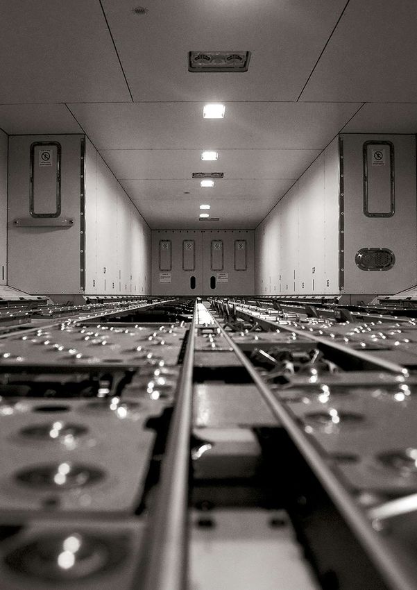
editorial
                         As we began the new year, Commercial Aviation Safety was already making headlines.
                         Fortunately, this was for the exceptionally low number of fatal accidents which occurred in
                         2017. It is a fantastic achievement and shows hugely encouraging progress. Yet as I am
                         fond of saying, we must never be complacent.

                         The industry continues strong growth in terms of the size of the world fleet and the volume
                         of operations. We have to redouble our efforts if we want to keep the number of accidents
                         at these all-time lows. There is no doubt in my mind that if we as an industry are to succeed
                         in further enhancing Safety, we will need to further reinforce our efforts in sharing Safety
                         information.

                         This magazine is a major contribution in Airbus’ efforts to share Safety information with our
YANNICK MALINGE          operators and the industry. We first started publishing a dedicated Safety magazine in June
SVP & Chief              1995, with ‘Hangar Flying’. The reaction to this magazine confirmed to us that the people
Product Safety Officer   using our products on a daily basis do indeed have a thirst for quality technical information
                         that helps them carry out their duties more safely, and with a deeper appreciation.

                         In 2004, we decided to change the name of our magazine to ‘Safety First’, to better reflect
                         its Safety objective, and so to boost its distribution and readership. The first issue came
                         off the press in January 2005, and since that time we have established it as a bi-annual
                         publication, built up a library of 25 issues, and created 120 individual articles.

                         But the world moves on, and we see that Safety First must move with it if we are to ensure
                         our readership is not only maintained, but also continues to expand. This is why we recently
                         sent out a short readers’ survey, collecting feedback and inputs on what changes would
                         be of value to you. I would personally like to thank those of you who answered this survey,
                         your help is very much appreciated.

                         Here are some of the key changes we will make that have been supported by your answers:

                         Increased frequency: 86% of respondents confirmed that they would like to receive articles
                         at a higher frequency, so that is exactly what we will do. We will start to publish individual
                         articles every six weeks in various digital formats. The paper magazine will still be available
                         every January and July.

                         Article search: An overwhelming 96% of respondents replied that an article search feature
                         would be useful. A new app is available this month organized around articles instead of
                         magazine issues, and including a search engine feature. Smartphones will get their own
                         dedicated apps, and later in 2018 there will be a Safety First website too.

                         Article topics: Feedback on what articles the respondents would like more of clearly indicates
                         a desire for more coverage of pilot knowledge & skills topics. Cabin safety is also requested
                         by the Safety Officers who replied. We will take this into account in planning our stories, and
                         you should expect to see some coming changes over the course of 2018.

                         So, having let you know how Safety First is moving forward, I leave you to move forward
                         yourself, through the pages of edition #25!
NEWS

                                              Vienna, Austria
                                            19-22 March 2018

                         Airbus
                         Flight Safety
                         Conference

The Airbus’ 24th annual flight safety conference
is the forum for Airbus and our customers to share
safety lessons learnt and best practices
It also provides a venue to establish networking opportunities between airline
Safety Officers and Fleet Management Pilots in addition to interacting with Airbus
Safety, Flight Test, Flight Ops, and Chief Engineering personnel.

SAFETY THEMES IN 2018:
  – Aircraft Energy Management
  – Control Inputs in Manual Flight
Both themes will be presented in their relevant phases of flight over the duration
of the conference.

ATTENDANCE & INVITATIONS
The 24 Airbus Flight Safety Conference will be held at the hotel Hilton Vienna,
Austria from 19 - 22 March 2018.
Invitations were sent to customers early January 2018.
To nominate an attendee, or to change contact information, please send an email
to Mrs Nuria Soler at nuria.soler@airbus.com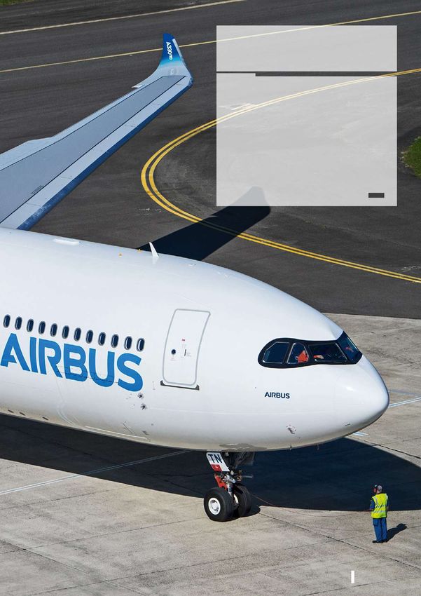
NEWS
New “Cabin Operations” domain and merge
of the “Engineering” and “Maintenance” domains
Because Cabin Crews play a key role in safety, we have created a new domain
called “Cabin Operations” that will ease identification of the articles that are
relevant for cabin crews.
To ease navigation and to limit the number of domains, we merged the
Maintenance and Engineering domains into a single “Engineering & Maintenance”
domain.

      Flight operations

      Cabin Operations

      Ground Operations

      Engineering & Maintenance

                                                                    NEWS
Evolution of the Safety first app
A new version of the Safety first app is available with several improvements:
- Article based application
- Search engine for quick access to specific topics
- Independent article publications
- Now compatible with any screen size: available for both tablets
  and smartphones.
Download the Safety first app from your app store:
Safety first #25 | January 2018   005

                            Safety
                            first #25

                                OPERATIONS
                                P06
                                Are You Properly Seated?

                                P14
                                A Recall of the Correct Use
Flight operations               of the MEL

Cabin Operations

Ground Operations               P24
                                Protecting Aircraft and
Engineering & Maintenance       Passengers from Cargo Fire
OPERATIONS
Are You Properly Seated?

Are You Properly
Seated?
The best position for a pilot to fly is not left to chance.
It is the result of detailed analysis and design that provides
the optimum seating position for both the Pilot Flying (PF)
and the Pilot Monitoring (PM) to safely and comfortably
operate their aircraft.
Safety first #25 | January 2018   007

                                                       It may be surprising that something as simple as the pilot’s seat
                                                       positioning can play a key role in the safe flying of an aircraft. This
                                                       is why it is important to pay close attention to the seat adjustment
                                                       phase during the “Before pushback and start” part of the Standard
                                                       Operating Procedures (SOP). This article will describe the principle
                                                       of Eye Reference Point and how this is pivotal in the design of an
                                                       Airbus aircraft’s cockpit. It will also illustrate how a pilot seated in
                                                       the correct position will avoid the potential consequences from
                                                       operating the aircraft with a poorly adjusted seating position.

CERTIFICATION REQUIREMENTS                                                                          When the pilots
                                                                                              align themselves with
Regulations require that the aircraft manufacturer provides a means which will aid the        the eye reference
pilots to position themselves with precision and allowing them to have the best point         point, they will have
of view from their seat. This is defined by the EASA CS 25.773 and FAA FAR 25.773.
                                                                                              adopted the optimum
A pilot who is between 1.58 m (5ft 2 inches) to 1·91 m (6ft 3 inches) tall shall have         position to operate
easy access to all of the aircraft’s controls in the cockpit and this is stipulated by EASA
CS 25.777. This requirement ensures that the design fits to the vast majority of pilots.      the aircraft.
These requirements are taken into account when a reference point is provided for
the design of any cockpit. It is often referred to as the design eye position and also
called eye reference point.

THE EYE REFERENCE POINT
Modern aircraft cockpits are built around the eye reference point. It is used to
size the cockpit windows and define the location of all the controls, displays and
instruments.

When the pilots align themselves with the eye reference point, they will have
adopted the optimum position to operate the aircraft.

An optimized field of view
The cockpit is designed so that when the pilot has aligned themselves to the eye
reference point; all of the instruments and displays on the front panel are in their
field of view (fig.1).
                                                                                    Eye Reference Point

                                                         Aircraft Reference Axis

                                                                  Cut-off Angle

                                                            Glareshield

                                                                     PFD/ND
                                                                                              (fig.1)
                                                                                              Eye reference point principle
OPERATIONS
Are You Properly Seated?

                                                 A pilot needs to have good situational awareness during a flight. Alignment using
                                                 the eye reference point enables the pilots to have an optimal field of view through
                                                 the cockpit’s windows to see what is around them outside the aircraft. The eye
                                                 reference point position ensures the pilot can maintain the best cut-off angle that
(fig.2)                                          will provide the longest visual segment (fig.2). This is especially important to get
Cut-off angle                                    visual references during Low Visibility Operations (LVO).

Aircraft Referenc
                     e Axis
                    Pitch
Horizon

                                           Cut-off
                                           Angle

                                              VR)
                                          e (S
                                    ang
                            Visual R                                          Blind Area
                        t
                   Slan

  Visual Segment
                                  Runway Visual Range (RVR)

                                                 A consistent viewpoint
                                                 Having a consistent viewpoint gives several operational advantages such as easing
                                                 the handling of the aircraft by providing pilots with a consistent visual reference,
                                                 repeatable at every flight. This is especially useful during final approach to be
                                                 familiarized with the final approach path angle and also for the flare phase.

                                                 Since the A300 Airbus has provided an eye reference indicator on the centre
                                                 structure of the windshield in all Airbus aircraft (fig.3). It enables flight crew to
                                                 adjust their seat position so that their eyes position matches the eye reference
                                                 point. The indicator is a device that is fitted with 3 balls painted red or white. To
                                                 achieve a correct seating position, pilots must align the red and white ball meaning
                                                 that the white ball is hidden when in the correct position.
(fig.3)
Example of the eye reference
indicator in the A350
                                                                           Eye
                                                                           Reference
                                                                           Indicator

                                                    Using Head Up Display (HUD)

                                                 HUD symbols are fully visible when the pilot’s eyes are closest to the eye reference
                                                 point. An “eye box” is defined as an area around the eye reference point that gives
                                                 a position tolerance range (fig.4). Hence the pilot correctly sees indications on
                                                 the HUD when their eyes are positioned inside this virtual box. The HUD eye box
                                                 area extends further aft than forward to allow HUD readability when seated in a
                                                 more reclined position for comfort.
Safety first #25 | January 2018 009
(fig.4)
HUD eyebox principle
An optimized access to aircraft controls
A pilot properly seated with their seat harness fastened is able to reach and operate
all of the aircraft’s controls through their full range of motion or deflection as it is
(fig.5)
defined by the design certification requirements (fig.5).
3D model to visualize the access
to flight controls
What if seated too low? In flight, if pilots
position themselves
A pilot seated in a position that is too low may have difficulties to reach all of
the system controls located on overhead panel. too low, during
final approach their
On ground, if seated too low while taxiing the aircraft, the pilots’ situational
awareness can be impaired to an extent where it may increase the risk of collision
perception
with airbridges, buildings, ground support vehicles or other aircraft on the ramp. of the flight path
angle may be
In flight, if pilots position themselves too low, during final approach their perception
of the flight path angle may be inaccurate. inaccurate.
Eye Reference Point
Aircraft Reference Axis
Reduced
Cut-off Angle
Blind
Area
Glareshield
PFD/ND
(fig.6)
Impact of a too low seating positionOPERATIONS
Are You Properly Seated?
Being seated too low can also create a blind area due to the glareshield, reducing
the cut-off angle and thus limiting the visual segment (fig.6 and 7). Such reduced
visual segment during approaches with poor visibility conditions, including Low
(fig.7) Visibility Operations (LVO), impairs the ability of the flight crew to obtain the proper
Cut-off angle when seated too low visual references for landing, increasing the likelihood of a go-around.
Aircraft Referenc
e Axis
Pitch
Horizon
Reduced
Cut-off Angle
)
ge (SVR
al Ran Blind Area
t Visu
Slan
Visual
Segment Runway Visual Range (RVR)
BEST PRACTICE
Towards the end of a flight, especially for long sectors, the pilot’s position may
change due to muscle fatigue often causing them to adopt a position that is
lower than at the beginning of the flight. Before commencing the approach,
it is recommended to re-adjust the seating position to make to reconfirm that
their visual reference is aligned with eye reference point and their position is
adjusted accordingly.
What if seated too high?
If the pilot has adjusted their seat to a position that is too high, then the same effect
can be experienced as for a pilot who has positioned themselves too low. During
final approach, the perception of the flight path angle may also be inaccurate.
If the pilots’ eye level is above the eye reference point, then the glareshield impairs
their view of the instrument panel and in some cases, hides the upper PFD and
ND from view (fig.8).
(fig.8) Additionally, operating the rudder pedals through their full range would be more
Impaired view on the instrument panel difficult.
when seated too high
Eye Reference Point
Aircraft Reference Axis
Top of PFD and
ND are hidden
Blind area
PFD/NDSafety first #25 | January 2018 011
BEST PRACTICE
During the cruise flight phase where the pilots’ eye level alignment is not as
critical, for increased comfort, it is common practice for the pilots to adjust
their seat to be out of the eye reference point position. However, and to be
prompt to face any unexpected situation, the pilots should still ensure that
they can reach all of the flight controls and their view of the control panels is
not impaired.
ADJUSTMENT PROCEDURE
The flight crew must adjust their seating position before the aircraft moves, typically
before the pushback or engine start according to the FCOM SOP.
How does a pilot adjust their seat to position themselves correctly?
Step 1: Adjust the seat longitudinal and vertical position to align your eye-level
with the eye reference indicator and also check that the glareshield does not
obstruct the view the upper PFD and ND (fig.9).
The white ball is completely
hidden behind red ball
Top of PFD and
ND not hidden
(fig.9)
Correct seat adjustment
Step 2: Adjust the armrest to a position where your hand can grip the sidestick
naturally without stretching the forearm and with a straight wrist. If the armrest is
correctly adjusted, your forearm should rest comfortably on the armrest and you
will only need to move your hand and fingers to give the appropriate inputs to the
sidestick (fig.10).
(fig.10)
Correct armrest adjustmentOPERATIONS
Are You Properly Seated?
Step 3: Adjust the Pedals position using the adjustment lever. Ensure the pedals
can be moved through their full range of motion with your feet they can be fully
deflected and that full manual braking can be applied.
Tip: Take a note of the positions of both the armrest and pedals on their associated
position indicators when your adjustment settings are correct and comfortable to
save time when making seat adjustments for your next flights (fig.11).
(fig.11)
Armrest position indicator
An armrest The importance of armrest and pedals adjustment
that is not properly A correct armrest adjustment for a comfortable and
adjusted makes precise manual flying
it more difficult to The hand is the most dexterous part of the body that is most capable to perform
make the appropriate the movements of the sidestick with the most precision. When the pilot’s armrest
is adjusted correctly, their hand is in a comfortable position without any strain
inputs during manual on the wrist, allowing for accurate inputs on the sidestick. An armrest that is not
flying. properly adjusted makes it more difficult to make the appropriate inputs during
manual flying and a pilot can be more prone to overreaction and make excessive
command inputs on the sidestick.
In addition, in turbulent conditions, the armrest stabilizes the pilot’s arm to avoid
involuntary sidestick inputs due to vibrations.
An incorrect rudder pedals adjustment can have strong impact in some
phases of flight
The ability to move the rudder pedal through their full range of motion is especially
The ability to crucial during the takeoff roll and initial climb after lift-off in the case of an engine
failure or strong crosswinds. It is also a critical control input that is necessary
move the rudder during the flare and roll out in engine out or in crosswind landing conditions.
pedal through their
When on the ground, the pilots’ seat and pedals positions must enable the pilot
full range of motion to apply maximum manual braking if it is required following a rejected takeoff roll
is crucial. or should it be required after landing.Safety first #25 | January 2018 013
Adjusting the seat position may be sometimes seen as an
CONTRIBUTORS: inconsequential step in the SOP. However, a poorly adjusted seating
Maurice GARNIER position can have significant effect on the pilot’s capability to make
Displays/Warning/ appropriate control inputs when flying or taxiing the aircraft.
HUD Systems
Engineering Adjusting the seat to be correctly positioned with the pilots’ eyes
Gilles MARQUET level aligned with the Eye Reference Point ensures that all of the
Cockpit Design aircraft flight controls and systems control panels can be reached
Engineering and operated properly. It is also crucial to ensure full visibility of all the
Vincent SIBELLE instruments or displays in the cockpit. Finally, it provides the optimum
Expert Pilot position for the pilot’s field of view from the aircraft to enhance their
Flight Operations Support situational awareness and have a correct perception of the flight path
angle during approach.
Flight crew should keep in mind that a seating adjustment done at
the right time ensures comfort and accurate aircraft handling in the
critical phases of flight.OPERATIONS A Recall on the Correct Use of the MEL A Recall on the Correct Use of the MEL The dispatch under a Minimum Equipment List (MEL) item allows to dispatch an aircraft in a safe and airworthy condition when certain system functions or equipment are temporarily unavailable or inoperative, enabling the aircraft to continue earning revenue without compromising the safety of the flight. But, what are the MEL principles and are there good practices to think about when dispatching an aircraft with an MEL item in the tech log?
Safety first #25 | January 2018   015

                                                 In the daily operations of an aircraft, failures that have an impact
                                                 the flight dispatch can happen. A lack of spare parts or other
                                                 constraints may make it unfeasible to fix the issue before the
                                                 next scheduled flight. Using the MEL to dispatch an aircraft with a
                                                 system function or equipment which is inoperative can avoid costly
                                                 operation disruptions and ensures that the safety of the aircraft
                                                 is not impaired. The operator can then schedule the necessary
                                                 maintenance action at the next most suitable opportunity such
                                                 as a return to a main base or a station when spares parts are
                                                 available. This article recalls the principles of the Master Minimum
                                                 Equipment List (MMEL) which is the baseline for the establishment
                                                 of the Operator’s Minimum Equipment List (MEL). It also provides
                                                 an overview of the best practices for using the MEL.

THE MMEL AND THE MEL

Definitions
  MMEL

The Airbus MMEL is a dispatch document that is produced by the aircraft                   The MMEL is
manufacturer and approved by the certification authorities.                          used as a reference
The MMEL is used as a reference by the Operators to create their own MEL,            by the Operators
which will permit the dispatch and operation of an aircraft with one or more         to create their
inoperative equipment or unavailable system function while maintaining an
acceptable level of safety.                                                          own MEL
  MEL

The MEL is a dispatch document developed by the Operator based on the aircraft
manufacturer’s MMEL. The MEL must be as restrictive as or more restrictive
than the MMEL and must be approved by the Operator’s national airworthiness
authorities.
                                                                                          The MEL must
The MEL permits the Operator to assess the impact on their operations (flight
schedule, route, environmental conditions,...) while operating an aircraft with
                                                                                     be as restrictive as
systems, functions or components inoperative, thus to optimize aircraft dispatch     or more restrictive
reliability and profitability without impairing safety.                              than the MMEL and
How is the MMEL developed?                                                           must be approved
                                                                                     by the Operator’s
The MMEL provides a list of items with associated conditions for dispatch.
For every item, Airbus must demonstrate that the associated dispatch conditions
                                                                                     national airworthiness
are compliant with the certification requirements as specified by EASA. The major    authorities.
steps of this demonstration are the following:

Step 1: Assessment of the MMEL item to identify any operational impact or impact
on other system functions, and check if there is any influence on the safety level
of the aircraft.
OPERATIONS
A Recall on the Correct Use of the MEL
Step 2: Identification and assessment of the operational and safety impact of the
next critical aircraft system failure which may occur during subsequent flights.
Step 3: Definition of any maintenance actions or operational procedures that may
be necessary as a means of mitigation for the assessed impacts of the MMEL item.
Based on the above assessments, a dispatch status is defined for each MMEL
item as either:
- “GO” when the dispatch is permitted for a limited period of time without
specific dispatch condition, or
- “GO IF” when the dispatch is permitted for a limited period of time with
specific dispatch conditions, or
- “NO GO” when the dispatch is not permitted and corrective maintenance
action must be undertaken before the aircraft can continue operations.
How is the MEL developed?
The Operator’s MEL is a dispatch document which should be tailored according to
the Operator’s routes, procedures and applicable local regulations, and within the
constraints defined by the aircraft manufacturer’s MMEL.
The Operator’s
MEL is a dispatch
document which
should be tailored
according to the
Operator’s routes,
procedures and
applicable local
regulations, and
within the
constraints defined
by the aircraft
manufacturer’s
MMEL. When does the MEL apply?
As per regulations, when there are failures or defects that cannot be rectified, and
which are covered by an MEL item, the MEL must be applied prior to departure
and accepted the Captain.
The “departure” corresponds to the “commencement of the flight”.
“The commencement of the flight” is defined as the moment when the aircraft
starts to move under its own power for the purpose of takeoff (i.e. the taxi phase).
EASA and FAA require Operators to define procedures in their MEL for the
management of any failure that occurs during the taxi-out phase.Safety first #25 | January 2018 017
EASA regulations
The EASA regulations require that Operators define an appropriate guidance for
flight crew for the management of failures if they occur between the start of taxi
and commencement of take-off roll.
The EASA regulations also state that the captain may decide to continue with the flight
based on their “good judgment and airmanship”. Additionally, their regulations allow
flight crew to consult the MEL if it will help them to make a decision. Communication
with dispatch, or the Operator’s maintenance control centre, may assist the flight
crew in their assessment of the MEL item and aid the Captain to decide if they will
continue with the flight or not.
The final decision to continue with the flight is the responsibility of the Captain.
This decision should be based on any operational considerations that could impair
the current flight and also consider any impact on the subsequent missions of the
aircraft.
FAA regulations
The FAA regulations require that Operators establish a procedure for the Pilot
In Command (PIC) to communicate with the aircraft dispatch and maintenance
organizations when a failure occurs after an aircraft departs the gate or ramp area,
during pushback, taxi or prior to take-off.
This procedure permits the flight crew to review the situation and determine if
the aircraft can be either dispatched with the failure under the MEL item, or if the
failure must be rectified before take-off. If a dispatch with the failure under the
relevant MEL item is advised, the return to the gate to accomplish the appropriate
maintenance or operational procedure must be considered. In coordination with
the Operator’s dispatch and maintenance organization, certain MEL procedures
may be accomplished by the flight crew without returning to the gate, provided
these procedures are approved by the FAA’s Principal Operations Inspector (POI).
Other Local regulations if a system or
Other National Aviation Authorities (NAA) may have regulations that differ from the
equipment defect
regulations defined by the EASA or by the FAA. It is the responsibility of each is detected during
Operator to check the applicable regulations with their relevant NAA. flight, the MEL
MEL consultation in flight information may be
useful to assess
The MEL is defined as a dispatch document and therefore the MEL is not
applicable in flight. However, if a system or equipment defect is detected during
the likely dispatch
flight, the MEL information may be useful to assess the likely dispatch condition condition for the next
for the next flight. A detailed description of the defect detected should be entered flight.
in the tech log, and Operator’s dispatch or Maintenance Control Centre notified
so they can consult MEL when the aircraft arrives.
What about multiple failures?
If several aircraft system functions or equipment are inoperative, operators should
consult the MEL for each individual item to check if there are any incompatibilities
for each of the associated dispatch conditions. If there is no MEL restriction, it
is the flight crew’s responsibility to assess the situation and to decide whether
or not to dispatch the aircraft with multiple inoperative items.OPERATIONS
A Recall on the Correct Use of the MEL
RULES AND
RECOMMENDATIONS
ON HOW TO USE THE MEL
From the moment of the failure has occurred until the dispatch of the aircraft, the
following steps should be followed to ensure that the aircraft can be dispatched
in an airworthy condition.
Step 1: Detection of the failure
A failure is detected:
-Through an ECAM alert or an indication on the Master Warning Panel (A300
B2/B4 only) or a failure indication on the Maintenance Panel (A300/A310 only)
- Through an observation of the flight crew by:
• A flight deck effect (missing indication, amber indication on a System Display
(SD) page, inoperative button or display, etc...)
• A defective component detected during the external walkaround
(e.g. external light not illuminating)
-Through an observation of the maintenance personnel.
Any aircraft Step 2: Reporting the failure
system function Any aircraft system function unavailability or equipment failure has to be reported
unavailability or in the technical logbook by the flight crew.
equipment failure has This technical logbook entry is the starting point for assessing any defect using
to be reported in the the MEL. The flight crew should write any additional information associated to
technical logbook by the defect that will help identify the cause of the defect such as the ECAM alert
title, time of occurrence, SD page indication and flight phase.
the flight crew
Line Maintenance personnel can also make an entry in the aircraft’s technical
logbook to report any system function defect or inoperative equipment detected
during ground operations.
NOTE
Aircraft system defects detected in the passenger cabin may be reported by the
cabin crew in the cabin logbook. Should the defect have an impact on dispatch,
these entries must be transferred to the aircraft’s technical logbook before
assessing the relevant MEL item applicability.Safety first #25 | January 2018 019
Step 3: Identification of the correct dispatch
condition or MEL item associated to the failure
The identification of the failure is usually based on the ECAM alert’s title and
the dispatch assessment is provided in the MEL Entries section under the
“CONDITION OF DISPATCH” header (fig.1).
(fig.1)
Example of a MEL entry with
an associated MEL item
KEYPOINT
If a failure is classified as “NO DISPATCH” (fig.2), the aircraft must not be
dispatched until the equipment or function is rectified.
(fig.2)
Example of a MEL entry with a
“NO DISPATCH” condition
In some cases, MEL Entries section may require additional action by the flight crew
or the maintenance crew in order to assess the dispatch conditions, particularly
when:
- One ECAM alert refers to several MMEL items (fig.3)
(fig.3)
Example of a MEL entry with several
associated MEL items
- The dispatch condition assessment depends whether the ECAM alert is actual
or false (spurious) (fig.4)
(fig.4)
Example of a MEL with dispatch condition
depending whether the alert is actual of falseOPERATIONS
A Recall on the Correct Use of the MEL
- The dispatch condition assessment requires additional information such as
ECAM indication on the SD page (fig.5)
(fig.5)
Example of a MEL entry with the dispatch
condition depending on indications on the
associated SD page
On A350, the ECAM Dispatch Messages are a straight forward help for dispatch.
The flight crew finds the Dispatch Message in the MEL entries section to get the
condition of dispatch or identify the applicable MEL item (fig.6)
(fig.6)
Example of a Dispatch Message on A350
The A380 and A350 MEL also show a “Crew Observations” section in the
MEL entries (fig.7) covering failures of monitored systems that are indicated
with flight deck effects that don’t have an associated ECAM alert or Dispatch
Message, for example, an amber indication on system display (SD) page or when
the FAULT light of a pushbutton switch illuminates. The “Crew Observations”
section also covers malfunctions that can be visually detected by the flight crew
or the maintenance personnel, for example during the external walk around.
(fig.7)
Example of a Crew Observation in the MEL
Entries section on A380
If the failure is not linked to an ECAM alert or to a failure reflected in the Crew
Observation section (A380 & A350), the correct MEL item should be identified
directly into the MEL items section.
KEYPOINT
It is important to identify the MEL item correctly. The application of a MEL item that
does not correspond to the inoperative equipment or unavailable system function
may have unintended consequences for the safety of the flight.Safety first #25 | January 2018 021
Step 4: Review of the dispatch conditions
When the MEL item is correctly identified, the flight crew should carefully review The application
the dispatch condition. of a MEL item that is
If there are several dispatch conditions, the title of the associated dispatch not corresponding
condition helps to identify which one is applicable (fig.8). with the inoperative
equipment or
unavailable system
function may
have unintended
consequences for
the safety of the
flight.
(fig.8)
Example of a MEL item with two dispatch
conditions: 36-12-02A and 36-12-02B
Step 5: Decision for dispatch
Maintenance personnel may propose to dispatch the aircraft under MEL item
provided that all of the associated dispatch conditions are fulfilled.
It is the Captain’s responsibility to accept the aircraft dispatch under the MEL item
for the flight; taking into account not only the MEL dispatch condition but also the
applicable operator’s policy and the operational constraints.
It is
the Captain’s
responsibility to
accept the aircraft
dispatch under
the MEL item
for the flightOPERATIONS
A Recall on the Correct Use of the MEL
Step 6: Log of the MEL item
Inoperative The maintenance personnel must make an entry into the logbook for the MEL
items should be item and determine the deadline for rectification based on the MEL repair interval.
repaired as soon as Inoperative items should be repaired as soon as possible and at least within the
possible and at least period of time defined by the repair interval (fig.9).
within the period of
time defined by the
repair interval BEST PRACTICE
Plan the repair as soon as possible to avoid operational disruption should
additional failure occur that may make the dispatch impossible.
The allowable intervals for rectification are classified as the following:
Interval A B C D
Calendar Refer to interval 3* 10* 120*
Days provided in MMEL item
*Excluding the day the defect was first detected
In-flight No Dispatch due
failure MEL Repair Interval (B = 3 Calendar Days) to repair interval
MEL exceedance
! Dispatch during flight
Flight 1 Flight 2 Flight 3 Flight 4 Flight 5
(fig.9)
Principle of the repair interval
Day of
Day 1 Day 2 Day 3
Discovery
0h 0h 0h 0h 0h
Specificity of Category “A” repair intervals
MEL with category “A” repair intervals can use different references, e.g. calendar
days, flight cycles…
Step 7: Initial dispatch
For the first dispatch after applying the MEL item, all dispatch conditions and
associated limitations must be accounted for and any relevant maintenance (m)
and operational (o) procedures must be applied to maintain an acceptable level
of safety for the operation of the aircraft, even with the inoperative equipment or
unavailable system function.
BEST PRACTICE
For a complete awareness of aircraft dispatch condition, maintenance personnel
should also consult the operational procedure (when applicable).Safety first #25 | January 2018 023
KEYPOINT
An incorrect or incomplete application of the maintenance or operational procedure
may impair the safety of the flight.
Step 8: Subsequent flights dispatched under MEL An incorrect
item
or incomplete
application of
For the subsequent flights, the flight crew must check that any open MEL item the maintenance
in the logbook is within the window of the repair interval and that this time limit
won’t be exceeded during the next flight mission. or operational
procedure may
When the dispatch conditions are accepted by the captain (as described in step
5), all necessary operational procedures must also be applied.
impair the safety
of the aircraft.
In the case when a new MEL item is recorded in the technical logbook, the
maintenance personnel must also review all of the pre-existing MEL items to
ensure that all of the dispatch conditions for each item are fulfilled.
KEYPOINT
In the case of a multiple MEL items logged, flight crew and maintenance personnel
must check before each flight that dispatch conditions of all MEL items are fulfilled.
The MEL is a commonly used tool allowing for the safe and continuous
CONTRIBUTORS: operation of the aircraft until rectification of certain inoperative equipment
Yannick DUMOLLARD or unavailable system functions that are not adversely affecting the
MMEL Expert airworthiness of the aircraft. But incorrectly using the MEL could lead
Flight Operations Support
to dispatching an aircraft in a configuration that is not airworthy and
with potential consequences that could impair the safety of the flight.
Understanding the principles and rules for correctly applying MEL items
is crucial for both maintenance personnel and flight crews.
When dispatching under a MEL item, the conditions of dispatch and
the rectification interval must be taken into account and the associated
maintenance and operational procedures must be accurately applied.
It is ultimately the Captain’s responsibility to decide to dispatch the
aircraft for flight under the MEL conditions.OPERATIONS Protecting Aircraft and Passengers from Cargo Fires Protecting Aircraft and Passengers from Cargo Fires Cargo compartment linings are designed to provide an air-tight space, and are essential in protecting the aircraft and its occupants from fire and smoke. This article looks at how these composite components have come to play such an important role in Safety, and what can be done to make sure they stay in good condition.
Safety first #25 | January 2018   025

                                                   Aircraft certification requirements for cargo compartment fire
                                                   protection have evolved in response to a number of tragic events.
                                                   Today’s design standard for lower deck cargo holds relies on
                                                   the flame-proof and air-tight properties of the compartment liner.
                                                   Inspecting the liner and making repairs when needed is important
                                                   to keep it in good condition.

CARGO COMPARTMENT FIRES
& THE EVOLUTION OF DESIGN
STANDARDS

Origins of the fire containment principle
Regulations providing design criteria for cargo compartments in commercial                    In 1952
aircraft were introduced in 1946, prior to the introduction of the first jet aircraft
into commercial aviation. At this time, the criteria considered that cargo
                                                                                        fire containment
compartments would either be accessible to the crew and a fire would be                 designs relying on
manually extinguished, or inaccessible and equipped with fire detection and             restricting oxygen
extinguishing systems.
                                                                                        supply became
Changes to regulations introduced in 1952 allowed for new types of inaccessible         permitted
cargo holds called ‘Class D’ compartments. Designs were permitted to rely
purely on fire containment principles, by having linings designed to be capable
of restricting the supply of oxygen into the compartment, without needing any
fire detection and suppression systems.

With the introduction of larger passenger jets, the size of Class D compartments
grew beyond that for which the 1952 regulations had originally been intended.
Larger compartments introduced new risks, including larger quantities of
combustible material, and the presence of a larger volume of oxygen.

The combination of these two factors created the possibility that a fire starting in
such a hold could burn for sufficient time or with sufficient strength that it would
penetrate the cargo hold linings. Penetration of the linings would of course lead
to availability of an increased oxygen supply, and an uncontrollable fire.

In-service events
A number of uncontrolled fires have occurred in cargo compartments, which                    In 1980 an
contributed to an evolution of airworthiness regulations. The FAA’s ‘Lessons            uncontrollable fire
Learnt from Civil Aviation’ website identifies two tragic fatal accidents which
were pivotal in driving this evolution.                                                 occurred in the
                                                                                        rear cargo hold of a
In 1980 in Riyadh, shortly after take-off of a second generation wide-body
aircraft, an uncontrollable fire occurred in the rear cargo hold. Tragically, all 301   second generation
passengers and crew died in the event.                                                  widebody aircraft
The accident report of the Saudi Presidency of Civil Aviation included the
conclusion that “Investigative evidence and testing indicates that the C-3, Class
D compartment of the L-1011 did not meet the intent of the FAR 25.857 (d) and
that the FAR is inadequate for purpose”.
OPERATIONS
Protecting Aircraft and Passengers from Cargo Fires
In 1996 in the Everglades near Miami, a second generation single-aisle aircraft
experienced an uncontrolled fire in its forward cargo compartment shortly after
takeoff, leading to the death of all 110 passengers and crew.
The accident investigation report written by the US NTSB identified the following
In 1996, a second findings related to the design standard of the aircraft type:
generation single-aisle “[…] a smoke/fire warning device would have more quickly alerted the pilots to
crashed after takeoff the fire and would have allowed the more time to land the airplane”
with the death of 110
“If the plane had been equipped with a fire suppression system, it might have
passengers & crew suppressed the spread of the fire […] and it would have delayed the spread of
the fire, and in conjunction with an early warning, it would likely have provided
time to land the airplane safely.”
Hence, these and similar accidents highlighted the need to update Part 25
airworthiness regulations regarding the means of fire protection in cargo holds,
including through design of the compartment lining as well as by detection and
suppression systems.
Changes to regulations
Following the accident in Riyadh, amendment 25-60 to Part 25 airworthiness
New legislation regulations was made effective in 1986 by the FAA. This amendment established
established more more stringent flame resistance standards for compartment linings, to take
account of the findings of a series of full-scale tests by the FAA to investigate the
stringent flame capability of different liner materials.
resistance standards
A retrofit activity was mandated to some of the existing fleets of the time in order
for liner materials to ensure cargo compartment panel linings were upgraded. This completion date
of this retrofit was established by the legislation as March 1991.
It was subsequent to the Everglades accident in 1996 that the limitations of the
principle of relying purely on containment by oxygen starvation were acknowledged.
In particular it was recognised that new risks needed to be considered, including
potential explosions of consumer aerosol products which could damage the
integrity of cargo compartment linings.
Recognising that under such circumstances, the only way to contain a fire would
Fire detection and be through active fire detection and suppression, in 1998 the FAA introduced
suppression systems new legislation through Amendment 25-93 to 14 CFR 25.855, which removed
the Class D cargo compartment category.
became mandatory
This meant that all new designs of aircraft, as well as existing aircraft in-service,
were to be equipped to the standards of Class C compartments, or Class E
compartments for freighter aircraft. In particular, fire detection system capable
of alerting the flight crew within 1 minute of the fire starting became necessary,
together with Halon gas fire suppression systems. The limit date for retrofits of
existing fleets was set at March 2001.Safety first #25 | January 2018 027
Type Crew Fire Extinguishing or Ventilation Flames, Smoke
Access Detection Suppression & Fumes
A Possible By crew at By crew with
workstation extinguisher
B Possible By detection By crew with Means to
system extinguisher exclude
from cabin
C Not possible By detection By dedicated Means to Means to
system system control to enable exclude
extinguishing from cabin
D Not possible None required None required No ventilation into Means to
compartment exclude
from cabin
E By detection Means to shut Means to
system off to enable exclude
extinguishing from cabin
Table 1 Post 25-93, types A, B, C & E remain Post 25-93, type D compartments no
Cargo Compartment Types in use in commercial aircraft longer exist in 25.855
CURRENT DESIGNS OF LOWER
DECK CARGO COMPARTMENTS
Following the tragic events described earlier in this article, the design standard Cargo
of lower deck cargo compartments was revised across the air transport industry,
with Class C type compartments and cargo compartment panel fireproofing
compartments
improvements being mandated. must be air-tight
and resistant to
This industry wide action significantly improved the fire protection level of
commercial aircraft through the equipping of the commercial fleet with key burning
features:
• Air-tight & fire-proof cargo holds
• Cargo fire detection systems
• Cargo fire suppression systems
These three features are all necessary and must all work together in order to
ensure that the aircraft and its occupants is protected from a cargo fire.
Making the cargo hold air-tight
The volume of lower deck cargo holds on Airbus aircraft varies significantly depending
upon the aircraft type and hold, but can range from as low as 7.0m³ (250ft³) on
an A318 to 143m³ (5050ft³) on an A340-600. Enclosing such voluminous spaces
obviously requires the use of many components.OPERATIONS
Protecting Aircraft and Passengers from Cargo Fires
1 Ceiling panels
1
2 Decompression panels 2
6 7
3 Vertical sidewall panels
3
4 Sloping sidewall panels
4
5 Floor panels
6 Partition
5
7 Door
The air-tight Lower deck cargo holds are constructed out of their doors, and many composite
panels attached to the aircraft’s primary and secondary structure. Various
lining of the cargo categories of panels are used, including ceiling, sidewall, sloped and floor panels,
compartment as illustrated in Figure 1. Even if we just consider the sidewalls and ceilings, a
is created by shipset of these different panels for a specific hold can include anything from 42
on an A320 up to 188 on the A380.
composite panels
together with their Together with their fasteners, secondary structure, and the cargo door, these
panels create the liner of the cargo hold lining. This liner is required to provide the
fasteners, secondary two fire protection functions of air-tightness and fire-proofing.
structure and the
cargo door. Air-tightness limits the available oxygen to any fire occurring within the cargo hold
compartment. It is a key safety measure which allows to suffocate a fire, as well
as to ensure that fire suppression systems have the required effect by creating
an enclosed space within which the Halon gas can act.
Air-tight seals between the panels and the structure are achieved by the use of
self-adhesive elastomer foam tapes applied to the rear of the panels. The seal
is made when these tapes are compressed during tightening of the fasteners.
Fire-proofing the cargo hold
The second fire protection function of the liners and panels is to withstand burning.
This function ensures that the passenger cabin is kept free of fire, as well as any
hazardous smoke and gases. Clearly, in the case of any fire, flame resistance of
the linings is essential to maintaining air-tightness.
Panels and all materials used in construction of the cargo compartment liner are
required by aircraft certification regulations CS-25.855 to meet flame resistance
properties are defined by airworthiness regulations.
The process to demonstrate compliance with this regulation is detailed and
rigorous, involving specific test equipment and the exposure of sets of production
standard panels to flames at a temperature of 927°C / 1700°F.Safety first #25 | January 2018 029
Detecting & suppressing a fire
Fire detection systems are designed to alert flight crew on the cockpit within Any damage or
1 minute of a fire starting. Based on the information provided by the detection mis-installation of the
warnings, flight crew initiate the suppression of any fire by discharge of Halon gas
into the affected cargo compartments. cargo compartment
lining can degrade
Halon is a very effective suppression agent which operates by chemically reacting
with the radicals generated by a fire, to inhibit the reaction. the performance of
the fire suppression
To achieve the extinguishing effect, sufficient Halon needs to be released to achieve
a volumetric concentration of 5% of the compartment air as a first shot, for a fire
system
knock-down effect. Following this, a concentration of 3% must be continuously
maintained for the rest of flight. With this approach, lower deck cargo compartment
fires can be suppressed for up to 360 minutes on wide-body aircraft.
Nevertheless, maintaining the concentration of Halon is crucial to the effectiveness
of the system, and therefore it is essential that the cargo compartment remains
air-tight. Any damage or mis-installation of the cargo compartment lining can
degrade the performance of the fire suppression system, and therefore has the
potential to make a key defence against on-board fires ineffective.
Certification of the A350-1000 fire suppression
system
To comply with the airworthiness authorities’ certification requirements, aircraft
manufacturers must prove that a new aircraft type’s fire suppression system can
maintain the required amount of Halon present in a cargo compartment over time.
Traditionally, this activity has only been possible by flight test, usually requiring
five individual flights.
For the certification of the A350-1000, Airbus has taken advantage of the
successful flight test campaign performed for the A350-900 and developed a
Computational Fluid Dynamic (CFD) model of the cargo hold together with its
Halon release system. Both EASA and the FAA have accepted this model as an
acceptable means of compliance. This significant advancement will enable Airbus
to perform more complex analyses in the support of Safety objectives.
CFD simulation of halon discharge into
the aft cargo hold of the A350-1000OPERATIONS
Protecting Aircraft and Passengers from Cargo Fires
MAKING SURE THE CARGO
COMPARTMENT IS IN GOOD
CONDITION
Cargo unloading and loading operations are a crucial part of the often time
constrained ground handling operations, so it hardly needs to be mentioned
that the cargo compartment can experience rough treatment. Whilst cargo
compartment liners are designed to be tolerant of such an environment, damages
do occur.
To make sure that the crucial fire protection function of the cargo compartment
lining is assured, regular maintenance inspections are required by the Maintenance
Planning Document. Additionally, the IATA Ground Operations Manual specifies
that a cargo hold inspection should be completed after each unloading operation.
Scheduled inspections
The Maintenance Planning Document (MPD) of all Airbus aircraft specifies a regular
visual inspection of each cargo hold. The maintenance procedures associated
with the MPD tasks specify a general visual inspection of the entire compartment,
including all types of panels identified in figure 1, to identify any damage or
deformation, or any panels which are in the wrong position.
Other elements which must be inspected include panel seals, fastener assemblies,
and the position of decompression panels.
Program MPD Revision MPD Task Number Interval
A350 Rev.03 Issue 501300-00001-01M 8 days
Jul 2015/16 01300-00004-01M 200 FH
A380 Rev. 13 Issue 501000-00101-01 16 days
Feb 01/17 501300-00001-01 750 FH
501400-00001-01 750 FH
501500-00001-01 750 FH
A330/A340 Rev.22 Issue 14 255200-00001-01 8 days
Sep 2017 255300-00001-01 8 days
255400-00001-01 8 days
A320 Family Rev.44 Issue Sep.2017 2550000-01-1 8 days
A300/A310 Rev.31 Jul 01/17 255100-01-1 8 days
255610-02-1 8 days
Inspections during cargo loading operations
On a daily basis, it is clear that the people who will have the most opportunity
to identify any damages or other issues with the cargo hold linings are ground
KEYPOINT operatives.
The IATA Ground Operations Manual There are no mandatory inspection requirements for ground operatives to
(GOM) states that ground crew must complete during cargo loading. However, ground operations procedures such
complete a final check of all holds to as those defined by IATA in the Ground Operations Manual (IGOM) provide a
inspect for damage reference for recommended safe practices during cargo loading operations, and
in practice also inform the expectations of local authorities.Safety first #25 | January 2018 031
IATA IGOM section 4.11 ‘Aircraft Loading’ contains a dedicated section 4.11.5
‘Cargo Hold Inspections’, with the following key recommendations in relation to
damage to the cargo holds:
• When an offload is completed, a final check of ALL cargo holds must be
conducted to inspect each cargo hold for damage to the compartment […]
• If any damage is found to the compartment […] it must be immediately reported
to a supervisor, the flight crew, and/or a company representative as required by KEYPOINT
the operating airline
• Any damage to the structure or linings of containerised or bulk holds may lead to The IGOM includes a checklist item
specific loading limitations. Therefore, any damage must be reported. The load for turnaround supervision staff, to
controller shall be informed accordingly. ‘Ensure all cargo holds offloaded
according to LIR (Load Instruction
In addition to section 4.11.5, cargo hold inspections are also specified in section report) and inspected for damage’.
6 ‘Airside Safety Operational Oversight’. This section of the GOM deals with the
activities which are expected to be performed by trained and qualified supervision
personnel of airlines and their subcontractors.
Turnaround Coordination/Supervision Requirements are defined in section 6.3
by the use of a checklist table, the primary purpose of which is to prevent unsafe
acts. Checklist item 11 states ‘Ensure all cargo holds offloaded according to LIR
(Load Inspection Report) and inspected for damage’.
TYPICAL REPORTS OF CARGO
COMPARTMENT DAMAGE AND
THEIR CAUSES
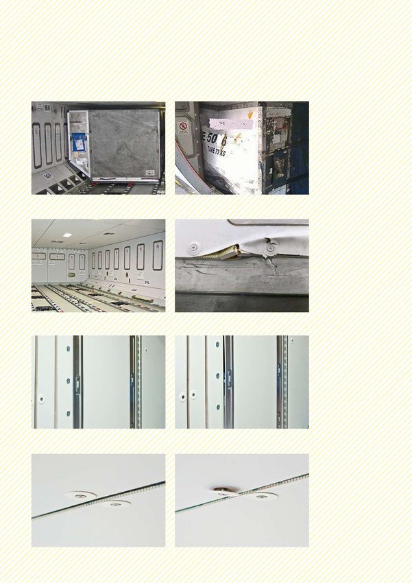
Typical abnormalities found during cargo compartment inspections are identifiable
from reports sent to Airbus by operator airlines. A study of reports over the period
2015-2017 reveals that types of abnormalities are generally quite consistent About 65% of
according to their source.
damages identified
Damage to sidewall panels, ceiling panels or cargo on widebody
doors from cargo operations aircraft are related
The majority of damage to cargo compartments are caused during cargo loading to the use of out
or unloading operations. Reports of such damage total around 65% of reports to of contour cargo
Airbus, and include cases of damage to vertical or sloping sidewall panels, ceiling
panels or doors. containers.
Typical damage identified on widebody aircraft types are related to out of contour
cargo containers or pallets impacting and/or scratching the sidewalls, with ceilings
being damaged less frequently. Damage to the cargo door linings are also typically
caused by impact with out-of-contour containers, and often result in cracking of
the panel around fixation holes upon door closure.
Additionally, poor maintenance of containers can make them more susceptible to
warping of the contour when under flight loads, leading to damage of sidewalls
and doors.
On A320 Family aircraft, both ceilings and sidewalls can be damaged during bulk
loading operations. This damage is usually due to abnormal impacts from bags and
suitcases under manual handling, and typically results in delamination or puncturing
of the top layer of the panels, or crushing of the honeycomb core.You can also read