Sample gas pumps P1.1, P1.1E - Installation and Operation Instructions - Bühler Technologies GmbH
←
→
Page content transcription
If your browser does not render page correctly, please read the page content below
Gas Analysis

                                                              Sample gas pumps

                                                                             P1.1, P1.1E

           Installation and Operation Instructions
                                                                   Original instructions

BE420020   Bühler Technologies GmbH, Harkortstr. 29, D-40880 Ratingen
03/2020      Tel. +49 (0) 21 02 / 49 89-0, Fax: +49 (0) 21 02 / 49 89-20
                    E-Mail: analyse@buehler-technologies.com
                     Internet: www.buehler-technologies.com
Bühler Technologies GmbH, Harkortstr. 29, D-40880 Ratingen
Tel. +49 (0) 21 02 / 49 89-0, Fax: +49 (0) 21 02 / 49 89-20
Internet: www.buehler-technologies.com
E-Mail: analyse@buehler-technologies.com

Read this instruction carefully prior to installation and/or use. Pay at-
tention particularly to all advises and safety instructions to prevent in-
juries. Bühler Technologies can not be held responsible for misusing
the product or unreliable function due to unauthorised modifications.

All rights reserved. Bühler Technologies GmbH 2022

Document information
Document No......................................................... BE420020
Version........................................................................ 03/2020

P1.1, P1.1E

Contents
1     Introduction.....................................................................................................................................................................................................................    2
      1.1   Intended use .........................................................................................................................................................................................................         2
      1.2 Product key............................................................................................................................................................................................................          3
      1.3 Scope of delivery ..................................................................................................................................................................................................             4
      1.4 Product description ............................................................................................................................................................................................                 4
2     Safety instructions......................................................................................................................................................................................................... 5
      2.1 Important advice ................................................................................................................................................................................................. 5
      2.2 General indication of risk ................................................................................................................................................................................. 6
3     Transport and storage .................................................................................................................................................................................................. 8
4     Installation and connection ........................................................................................................................................................................................ 9
      4.1 Requirements to the installation site............................................................................................................................................................ 9
      4.2 Installation ............................................................................................................................................................................................................ 9
      4.3 Special condition moist sample gas .............................................................................................................................................................. 9
            4.3.1   Conversion to pump body pointing down.................................................................................................................................. 10
      4.4 Connecting gas lines ......................................................................................................................................................................................... 11
      4.5 Electrical connections ....................................................................................................................................................................................... 11
5     Operation and control ................................................................................................................................................................................................. 13
      5.1 Switching on the sample gas pump ............................................................................................................................................................. 13
      5.2 Operating the sample gas pump.................................................................................................................................................................. 14
6     Maintenance................................................................................................................................................................................................................... 15
      6.1 Replacing the inlet and outlet valves .......................................................................................................................................................... 16
      6.2 Replacing the O-ring on the bypass valve (optional) .............................................................................................................................. 16
      6.3 Replacing parts inside the pump housing.................................................................................................................................................. 17
      6.4 Replacing the bellow ......................................................................................................................................................................................... 17
      6.5 Crank gear replacement.................................................................................................................................................................................. 18
      6.6 Assembly of the sample gas pump .............................................................................................................................................................. 18
7     Service and repair......................................................................................................................................................................................................... 19
      7.1 Troubleshooting ............................................................................................................................................................................................... 20
      7.2 Spare parts and accessories .......................................................................................................................................................................... 20
8     Disposal ............................................................................................................................................................................................................................ 21
9     Appendices..................................................................................................................................................................................................................... 22
      9.1 Technical data .................................................................................................................................................................................................... 22
      9.2 Feed curve............................................................................................................................................................................................................ 22
      9.3 Dimensions P1.1 (115 V / 230 V)....................................................................................................................................................................... 23
      9.4 Dimensions P1.1 (12 V DC or 24 V DC) ........................................................................................................................................................... 23
      9.5 Dimensions P1.1E Pumpe (all voltages) ....................................................................................................................................................... 24
10 Attached documents ................................................................................................................................................................................................... 25

BE420020 ◦ 03/2020                                                                                                                                                                       Bühler Technologies GmbH                           i
P1.1, P1.1E

1 Introduction

1.1 Intended use
The sample gas pumps are intended to be installed in gas analysis systems in industrial applications. Sample gas pumps of the
P1.1 type must be installed in a housing / equipment cabinet or provided with protection against accidental contact. The P1.1E
types come provided with a factory-made housing.
The sample gas pump is intended exclusively for the pumping of gaseous media. It is not suitable for liquids.
Please note the specifications in the data sheet on the specific intended use, existing material combinations, as well as pressure
and temperature limits.

       DANGER         Potentially explosive atmosphere
                      Explosion hazard if used in hazardous areas.
                      The device is not suitable for operation in hazardous areas with potentially explosive at-
                      mospheres.
                      Do not expose the device to combustible or explosive gas mixtures.

2    Bühler Technologies GmbH                                                                                      BE420020 ◦ 03/2020
P1.1, P1.1E

1.2 Product key
The device is delivered with different configurations. The part number given on the type plate informs you about the specific
configuration of your device.
On the type plate you will find the order number as well as the 13-digit product key. This number is a code where each digit (x)
describes a certain feature:

42 28 x     x   x    1   x   x   x 00 xx Product feature
                                             Motor voltage
        1                                    230 V 50 Hz 0.48 A
        2                                    115 V 60 Hz 0.84 A
        3                                    12 V DC 1.55 A (on request)
        4                                    24 V DC 0.8 A
                                             Pump head position
            1                                Normal position vertical
            2                                turned by 180°
                                             Pump head material
                1                            PTFE
                2                            VA (1.4571)
                3                            PVDF with bypass valve
                4                            PVDF
                                             Valve material
                     1                       up to 70 °C; PTFE/PVDF
                                             Screw-in connections/pipe fittings
                         0                   without
                         1                   PVDF DN 4/6 *
                         2                   PVDF 1/4”-1/6” *
                         3                   PVDF 1/4"-1/8" *
                         5                   VA (1.4401) 6 mm **
                         6                   VA (1.4401) 1/4" **
                                             Mounting accessories
                             0               without
                             1               Mounting bracket and set of vibration dampers
                             2               set of vibration dampers only
                                             Housing
                                 0           without
                                 1           Housing incl. 3 m connection cable
                                 2           Housing with on/off switch incl. 3 m connection cable ***
                                             Options
                                     00      without
                                             Approval
                                          -- without
                                          FM FM-Approval
* PTFE or PVDF pump body only
** VA pump body only
*** not possible with 12V/24V and/or FM approval
If there are special instructions for a pump type, they are marked in the manual.
Take care of the limits of the pump. When ordering spare parts chose for the type matching part numbers (e.g. valves).

BE420020 ◦ 03/2020                                                                                       Bühler Technologies GmbH   3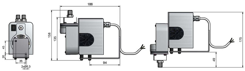
P1.1, P1.1E

1.3 Scope of delivery
– 1 x Sample gas pump with motor
– Product documentation
– Connection- and mounting accessories (only optional)
For logistics reasons, connection- or mounting accessories such as screw-in connections and/or mounting bracket are not fact-
ory installed!

1.4 Product description
The sample gas pump is designed to transport only gaseous media not liquids.
Please observe the information at the end of these instructions in relation to specific intended use, available materials, pressure
and temperature ranges. Regard in particular the information and type of protection given on the type plate.
Sample gases, which still contain humidity, tend to form condensate in the tubes and in the pump body. In such cases the pump
head must be mounted with the head pointing down (see chapter Conversion to pump body pointing down).

       NOTICE
                      Never use sample gas pumps outdoors!

4    Bühler Technologies GmbH                                                                                    BE420020 ◦ 03/2020
P1.1, P1.1E

2 Safety instructions

2.1 Important advice
Operation of the device is only permitted if:
– the product is used under the conditions described in the installation- and operation instruction, the intended application
  according to the type plate and the intended use. In case of unauthorized modifications done by the user Bühler Technolo-
  gies GmbH can not be held responsible for any damage,
– when complying with the specifications and markings on the nameplates.
– the performance limits given in the datasheets and in the installation- and operation instruction are obeyed,
– monitoring devices and safety devices are installed properly,
– service and repair is carried out by Bühler Technologies GmbH,
– only original spare parts are used.
This manual is part of the equipment. The manufacturer keeps the right to modify specifications without advanced notice. Keep
this manual for later use.

Signal words for warnings
                     Signal word for an imminent danger with high risk, resulting in severe injuries or death if not avoided.
    DANGER

                     Signal word for a hazardous situation with medium risk, possibly resulting in severe injuries or death if not
    WARNING
                     avoided.

                     Signal word for a hazardous situation with low risk, resulting in damaged to the device or the property or
    CAUTION
                     minor or medium injuries if not avoided.

                     Signal word for important information to the product.
     NOTICE

Warning signs
In this manual, the following warning signs are used:

         Warning against hazardous situations                            General notice

         Warning against electrical voltage                              Disconnect from mains

         Warning against respiration of toxic gases                      Wear respirator

         Warning against acid and corrosive substances                   Wear eye/face protection

         Warning against potentially explosive atmospheres               Wear protection gloves

         Warning against hot surface

BE420020 ◦ 03/2020                                                                                    Bühler Technologies GmbH       5
P1.1, P1.1E

2.2 General indication of risk
The equipment must be installed by a professional familiar with the safety requirements and risks.
Be sure to observe the safety regulations and generally applicable rules of technology relevant for the installation site. Prevent
malfunctions and avoid personal injuries and property damage.

The operator of the system must ensure:
– Safety notices and operating instructions are available and observed,
– The respective national accident prevention regulations are observed,
– The permissible data and operational conditions are maintained,
– Safety guards are used and mandatory maintenance is performed,
– Legal regulations are observed during disposal,
– compliance with national installation regulations.

Maintenance, Repair
Please note during maintenance and repairs:
– Repairs to the unit must be performed by Bühler authorised personnel.
– Only perform conversion-, maintenance or installation work described in these operating and installation instructions.
– Always use genuine spare parts.
– Do not install damaged or defective spare part. If necessary, visually inspect prior to installation to determine any obvious
  damage to the spare parts.
Always observe the applicable safety and operating regulations in the respective country of use when performing any type of
maintenance.

       DANGER         Electrical voltage
                      Electrocution hazard.
                      a) Disconnect the device from power supply.
                      b) Make sure that the equipment cannot be reconnected to mains unintentionally.
                      c) The device must be opened by trained staff only.
                      d) Regard correct mains voltage.

       DANGER         Toxic, corrosive gases
                      The measuring gas led through the equipment can be hazardous when breathing or
                      touching it.
                      a) Check tightness of the measuring system before putting it into operation.
                      b) Take care that harmful gases are exhausted to a save place.
                      c) Before maintenance turn off the gas supply and make sure that it cannot be turned
                         on unintentionally.
                      d) Protect yourself during maintenance against toxic / corrosive gases. Use suitable pro-
                         tective equipment.

       DANGER         Potentially explosive atmosphere
                      Explosion hazard if used in hazardous areas.
                      The device is not suitable for operation in hazardous areas with potentially explosive at-
                      mospheres.
                      Do not expose the device to combustible or explosive gas mixtures.

6    Bühler Technologies GmbH                                                                                      BE420020 ◦ 03/2020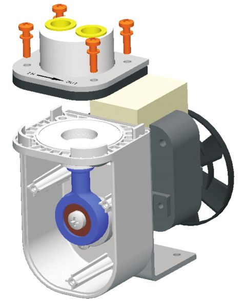
P1.1, P1.1E

     CAUTION         Tipping hazard
                     Equipment damage.
                     Secure the device against tipping, sliding and falling.

     CAUTION         Hot surface
                     Burning hazard
                     According to the product type and operation conditions, the temperature may exceed 50
                     °C during operation.
                     Depending on the conditions at the installation site it may be necessary to provide these
                     areas with appropriate warning signs.

BE420020 ◦ 03/2020                                                                                 Bühler Technologies GmbH   7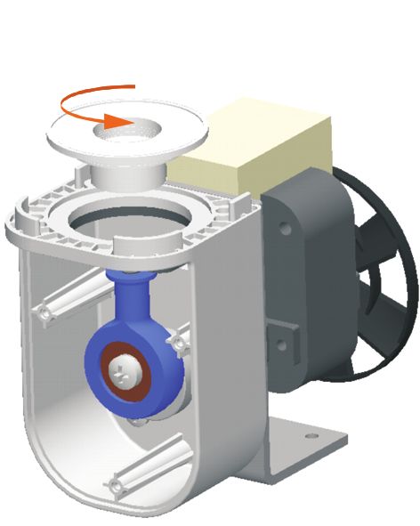
P1.1, P1.1E

3 Transport and storage
The products should be transported only in its original packaging or a suitable replacement.
When not in use, protect the equipment against moisture and heat. Keep it in a covered, dry and dust-free room at a temperat-
ure of -20 °C to +40 °C.
Outdoor storage is forbidden. As a matter of principle, the operator must regard all applicable standards according prevention
of damage due to lightning, which may otherwise damage the sample gas pump.
The storage room must not be equipped with any ozone-producing devices like fluorescent light sources, mercury arc lamps,
electric high voltage devices.

8    Bühler Technologies GmbH                                                                                BE420020 ◦ 03/2020
P1.1, P1.1E

4 Installation and connection
Remove any transport locks on the fan blade and check the equipment for damage prior to installation. This could be a damaged
housing, supply cables, etc., among other things. Never use equipment with obvious damage.

4.1 Requirements to the installation site
     CAUTION          Damage to the device
                      Protect the equipment against dust, falling objects and external impacts.
                      Stroke of lightning
                      Outdoor installation is forbidden. As a matter of principle, the operator must regard all
                      applicable standards according prevention of damage due to lightning, which may oth-
                      erwise damage the device.

The sample gas pumps are built-in units which may only be safely operated inside a housing providing adequate protection for
persons against touching live or moving parts (fans). Water and contaminants must also be prevented from entering. The P1.1E
sample gas pumps offers protection from direct contact with an IP20 rating. Depending on the operating and ambient condi-
tions, the required protection may vary and must be taken into account during installation.
Never block the vent, and the exhaust air – including from adjacent units – must not be immediately suctioned in.
The motor is rated for ambient temperatures of 0 °C to +50 °C as well as installation altitudes ≤ 1000 m above sea level.
Please refer to chapter "Appendix" at the end of the operating and installation instructions for additional installation site ambi-
ent parameters.

4.2 Installation
Use suitable rubber-metal buffers when installing to mounting plates. We recommend buffers with a diameter or 10 mm, a
height of 10 mm and a shore hardness of 70. These are also available from us.
The base angle of the sample gas pump features 4x M4 tapped holes for mounting the buffers. Suitable buffers and assembly
brackets are accessories which may be ordered separately from us.

While installing the sample gas pump, there must be sufficient spacing between the motor and the rear wall (20mm).
If you are using a sample gas pump with housing (type P1.1E), the required distance between the housing and the rear wall is
50mm. This is due to the minimum permitted bending radius of the power supply line.
The specific mounting bracket for the various product variants can be obtained as an accessory. Using the appropriate mount-
ing bracket guarantees the correct distance between the device and the rear wall.

4.3 Special condition moist sample gas
Applications where the sample gas is still moist may result in condensate forming in line and the pump body. In these events
the pump head must be suspended (pump body facing down).
If the pump was not ordered this way, it can easily be converted on site.
Install the line between the gas output and condensate drain with a grade so the condensate can drain and does not collect in-
side the pump or the lines.

BE420020 ◦ 03/2020                                                                                    Bühler Technologies GmbH    9
P1.1, P1.1E 4.3.1 Conversion to pump body pointing down Loosen the 3 Torx screws (M3x8) on the front cover (Torx T10). Remove the cover. Loosen and remove the 4 Torx screws (M4x6) on the console (Torx T20). Carefully turn the pump unit 180°. Then reinstall the 4 Torx screws and tighten to 3 Nm. Before tightening the screws be sure the pump unit is centered in the base angle. Now reinstall the front cover and secure using the 3 M3x8 Torx screws. 10 Bühler Technologies GmbH BE420020 ◦ 03/2020
P1.1, P1.1E

4.4 Connecting gas lines
The G1/4 female threads for the respective screw-in connections are factory closed with plastic plugs to protect from dirt. Screw-
in connections are generally not included in delivery, but are sold separately for metric or for imperial installation.
Avoid mixed-material installation, i.e. metal piping to plastic bodies. If this cannot be avoided in isolated applications, screw the
metal connections into the pump body with care, never use force.
Lay the lines so the line at the inlet and outlet remains flexible for an adequate distance.
The pumps are marked IN for inlet and OUT for outlet at the mounting ring. Be sure the gas line connections are tight.

4.5 Electrical connections
     WARNING          Hazardous electrical voltage
                      The device must be installed by trained staff only.

      CAUTION         Wrong mains voltage
                      Wrong mains voltage may damage the device.
                      Regard the correct mains voltage as given on the type plate.

A switch or circuit breaker (in accordance with IEC 60947-1 and IEC 60947-3) is to be provided. This must be organized to be easily
accessible for the operator. The switch must be labelled as an isolating device for the unit. It must not be inserted into a mains
power line or interrupt the protective conductor. Furthermore, the switch must separate the sample gas pump from the live
parts for all the poles.
The sample gas pump must be secured against unacceptable excessive warming by using a suitable overload protection (motor
protection circuit breaker). Sample gas pumps with a BLDC motor have already integrated protection against excessive warming
in the motor electronics.
Observe the rated current for the protective switch (230 V = 0,48 A, 115 V = 0,84 A, 12 V DC = 1,55 A, 24 V DC = 0,8 A).
Make sure that mains voltage and frequency meet the specifications of the motor (voltage tolerance ± 5 % and frequency toler-
ance ± 2 %.)
The electrical connection of type P1.1 is made with the help of flat connectors size 6,3 mm.
Sample gas pumps of type P1.1 (12 V DC/24 V DC) and P1.1E (all voltages) are delivered as standard with a 3 m connecting cable.
If your sample gas pump has a factory-installed on/off switch on the housing (only P1.1E), verify it is set to the zero position be-
fore connecting to power.

     WARNING          Hazardous electrical voltage
                      The On/Off switch does not ensure switching off all poles.

      It is essential to connect the protective earth conductor to the marked protection earth terminal. At model P1.1E
(115 V/230 V) the protective earth has to be connected to the green/yellow wire of the connection cable (see Fig. Electrical connec-
tion P1.1 pumps).
Select mains and protection earth cross section according to the rated current.
For the electrical connections especially for the protective conductor use a cable cross-section from minimum 0,75 mm2.
Obey differing specifications on the type plate. The conditions at the installation site must meet all specifications on the type
plate.
All parts under voltage must be protected through appropriate measures against contact by persons or foreign body proced-
ures.

BE420020 ◦ 03/2020                                                                                        Bühler Technologies GmbH     11
P1.1, P1.1E
P1.1 115 V/230 V P1.1 12 V/24 V
AC red = + 12 V/24 V blue = - 12 V/24 V
protection earth
P1.1E 115 V/230 V P1.1E 12 V/24 V
black = AC
brown = + 12 V/24 V
blue = - 12 V/24 V
green/yellow = protection earth
Fig. 1: Electrical connection P1.1 pumps
12 Bühler Technologies GmbH BE420020 ◦ 03/2020P1.1, P1.1E
5 Operation and control
NOTICE
The device must not be operated beyond its specifications.
CAUTION Hot surface
Burning hazard
According to the product type and operation conditions, the temperature may exceed 50
°C during operation.
Depending on the conditions at the installation site it may be necessary to provide these
areas with appropriate warning signs.
DANGER Toxic, corrosive gases
The measuring gas led through the equipment can be hazardous when breathing or
touching it.
a) Check tightness of the measuring system before putting it into operation.
b) Take care that harmful gases are exhausted to a save place.
c) Before maintenance turn off the gas supply and make sure that it cannot be turned
on unintentionally.
d) Protect yourself during maintenance against toxic / corrosive gases. Use suitable pro-
tective equipment.
5.1 Switching on the sample gas pump
Before switching on the unit, check:
– the hose- and electrical connections are not damaged and correct installed.
– no parts of the sample gas pump have been removed (e.g. cover).
– the gas inlet and outlet of the sample gas pump are not closed.
– the pre-pressure is below 0.3 bar.
– a bypass is installed for continuous operation for throttling below 150 L/h
– ambient parameters are met.
– data on the rating plate is met.
– the voltage and frequency of the motor match the mains values.
– electrical connections are securely connected and monitoring devices are connected and set as prescribed.
– air inlets and cooling surfaces are clean.
– ventilation slots in the housing cover are not covered or dirty, but are freely accessible.
– precautions have been taken; earthing!
When switching the sample gas pump on make sure that
– no abnormal sounds or vibrations occur.
– the flow rate is neither too low nor too high. This would indicate a cracked bellow.
BE420020 ◦ 03/2020 Bühler Technologies GmbH 13P1.1, P1.1E
5.2 Operating the sample gas pump
CAUTION Risk of injury by moving parts
The device may be damaged if it falls down of by impacts. Pay attention to any accessible
moving parts.
Operation without cover or with damaged cover is not allowed!
The sample gas pump is suitable for delivering gases only. It is not suitable for liquids.
The sample gas pump should be operated without pressure. A system pressure above 0.3 is not allowed. The gas outlet must not
be closed. The flow rate must be at least 50 l/h (150 l/h with system pressure 0.3 bar). If the flow rate continuously is throttled be-
low 150 l/h during operation, the flow rate must be controlled with a bypass valve.
NOTICE
Extreme throttling reduces the life time of the bellow.
If the pump is equipped with a bypass valve, the flow rate can be adjusted. Do not apply force when turning the valve, because
the valve may be damaged otherwise! The turning range of the valve is about 5 turns.
14 Bühler Technologies GmbH BE420020 ◦ 03/2020P1.1, P1.1E
6 Maintenance
Maintenance work on the device must be carried out in a cooled state.
The following section describes repair, maintenance and conversion work that can also be carried out easily by you on site,
without the sample gas pump having to be sent to us.
During maintenance, remember:
– The equipment must be maintained by a professional familiar with the safety requirements and risks.
– Only perform maintenance work described in these operating and installation instructions.
– When performing maintenance of any type, observe the respective safety and operation regulations.
NOTICE
Please refer to the assembly drawings in the appendix when carrying out maintenance.
DANGER Electrical voltage
Electrocution hazard.
a) Disconnect the device from power supply.
b) Make sure that the equipment cannot be reconnected to mains unintentionally.
c) The device must be opened by trained staff only.
d) Regard correct mains voltage.
DANGER Toxic, corrosive gases
The measuring gas led through the equipment can be hazardous when breathing or
touching it.
a) Check tightness of the measuring system before putting it into operation.
b) Take care that harmful gases are exhausted to a save place.
c) Before maintenance turn off the gas supply and make sure that it cannot be turned
on unintentionally.
d) Protect yourself during maintenance against toxic / corrosive gases. Use suitable pro-
tective equipment.
CAUTION Tipping hazard
Equipment damage.
Secure the device against tipping, sliding and falling.
CAUTION Gas leakage
The sample gas pump should not be dismantled under pressure.
CAUTION Hot surface
Burning hazard
According to the product type and operation conditions, the temperature may exceed 50
°C during operation.
Depending on the conditions at the installation site it may be necessary to provide these
areas with appropriate warning signs.
Depending on the composition of the sample gas, it may be necessary to replace the in- and out-let valves from time to time.
If the valves are heavily contaminated, especially after a short time, consider installing a particle filter upstream the pump. This
increases the service life significantly.
The screws of the fastening ring should be re-tightened after 500 hours of operation with torque 3 Nm.
BE420020 ◦ 03/2020 Bühler Technologies GmbH 15P1.1, P1.1E
6.1 Replacing the inlet and outlet valves
First detach the screw connections.
Unscrew the inlet or outlet valve with a wide slot screwdriver.
Attention: The PVDF and PVDF with bypass valve pump bodies already have PTFE gaskets installed in the gas inlets and outlets.
These are also included in the valve spare parts kit. Remove the old gaskets before installing the new ones.
The inlet and outlet valves are identical. Their installation position determines the function. As shown in the image, the valves
are blue on one side and black on the other. The valves are further marked “IN” or for inlet and “OUT” for outlet.
Inlet valve
Outlet valve
To assemble the sample gas pump, perform the steps in reverse order. When tightening the inlet and outlet valves be sure to ob-
serve the required tightening torque of max. 1 Nm. CAUTION! Tightening the valves more will permanently deform the pump
body, requiring replacement.
When installing the screw connection, ensure the connection is tight.
6.2 Replacing the O-ring on the bypass valve (optional)
– Loosen the two screws on the valve plate and carefully remove the entire unit.
– Coat the new O-ring with suitable O-ring grease (e.g. Fluoronox S90/2) and install in the spindle.
– Carefully insert the entire unit into the pump body while turning and tighten screws.
16 Bühler Technologies GmbH BE420020 ◦ 03/2020P1.1, P1.1E 6.3 Replacing parts inside the pump housing First detach the screw-in connections as described in chapter „Conversion to pump body pointing down“. Loosen the 4 Torx screws M4x18 (Tx20) and lift the pump head along with mounting ring and foam cover off the console. 6.4 Replacing the bellow To replace the bellow carefully unscrew it from the connecting rod counter clockwise. Be sure not to lose any installed shims. Before reinstalling the bellow be sure it is not damaged. Reinstall hand tight in reverse order. BE420020 ◦ 03/2020 Bühler Technologies GmbH 17
P1.1, P1.1E

6.5 Crank gear replacement
        NOTICE         Restrictions for connecting rod-eccentric replacement
                       The individual replacement of the eccentric, connecting rod or bearings is not allowed.
                       Only the factory pre-assembled connecting rod-eccentric combination is suitable for re-
                       placement by the operator.

The crank gear consists of the connecting rod with ball bearing and eccentric.
After removing the bellow remove the set-screw inside the eccentric M3 using a size 1,5 setscrew wrench (or Tx6 for torx drive de-
pending on the screw type).
The crank gear may now be removed from the motor shaft.
Before installing the replacement part remove any rust residue on the motor shaft and coat with non-resinous oil.
Reinstall the set screw with a drop of medium-strength threadlocker. When tightening the set screw, be sure it is seated in the
locking hole on the shaft. Once it touches the bore, tighten the set screw 90° more.

6.6 Assembly of the sample gas pump
If the sample gas pump was removed, install in reverse order. Be sure the sealing surfaces of the below and pump head are clean
and aren’t scratched (even minimal grooves can cause leaks). First evenly tighten the 4 Torx screws M4x18 at 1 Nm. Then tighten
the screws to 3 Nm.
CAUTION! Tighten each screw only once at 3 Nm. The bellow and pump body material (PTFE) is very weak and has high flow
properties.
Check the sample gas pumps for tightness and proper function.

18    Bühler Technologies GmbH                                                                                   BE420020 ◦ 03/2020
P1.1, P1.1E 7 Service and repair This chapter contains information on troubleshooting and correction should an error occur during operation. Repairs to the unit must be performed by Bühler authorised personnel. Please contact our Service Department with any questions: Tel.: +49-(0)2102-498955 or your agent If the equipment is not functioning properly after correcting any malfunctions and switching on the power, it must be inspected by the manufacturer. Please send the equipment inside suitable packaging to: Bühler Technologies GmbH - Reparatur/Service - Harkortstraße 29 40880 Ratingen Germany Please also attach the completed and signed RMA decontamination statement to the packaging. We will otherwise be unable to process your repair order. You will find the form in the appendix of these instructions, or simply request it by e-mail: service@buehler-technologies.com. BE420020 ◦ 03/2020 Bühler Technologies GmbH 19
P1.1, P1.1E

7.1 Troubleshooting
       CAUTION         Risk due to defective device
                       Personal injury or damage to property
                       a) Switch off the device and disconnect it from the mains.
                       b) Repair the fault immediately. The device should not be turned on again before elim-
                          ination of the failure.

       CAUTION         Hot surface
                       Burning hazard
                       According to the product type and operation conditions, the temperature may exceed 50
                       °C during operation.
                       Depending on the conditions at the installation site it may be necessary to provide these
                       areas with appropriate warning signs.

Problem / Failure                 Possible cause                                  Solution
Pump does not start               – Mains disrupted or not correctly moun- – Check fitting, fuse and switches
                                    ted
Pump does not transport           – Valves damaged or spoiled                  – Blow out valves carefully or replace them
                                  – Bypass valve open                          – Close bypass valve
                                  – Bellow cracked                             – Replace bellow
Pump noisy                        – Crank gear worn-out                        – Replace crank gear
Insufficient delivery rate        – Leakage                                    – Re-tighten the head screws, regard allowed
                                                                                 torque (see chapter Assembly of the sample gas
                                                                                 pump [> page 18]).
                                  – Bellow cracked                             – Check bellow and replace it, if necessary
                                  – Valves damaged or spoiled                  – Blow out valves carefully or replace them
Tab. 1: Trouble shooting

7.2 Spare parts and accessories
Please also specify the model and serial number when ordering parts.
Upgrade and expansion parts can be found in our catalog.
Available spare parts:

Spare part                                                             Item no.                 Pos. in spare parts drawing
                                                                                                42/018-Z03-01-2
Bellow                                                                42 28 00 3                18
Set inlet/outlet valves 70 °C                                         42 28 06 6                2 x 23/26
O-ring bypass valve                                                   90 09 39 8                28
Crankshaft assembly spare parts kit                                   42 28 06 5                6, 7, 8, 9, 10
Mounting bracket                                                      42 28 06 0                43a
Mounting bracket for housing version                                  42 28 06 7                43b
Set of bumpers incl. nuts & lock washers                              42 28 06 1                39, 40, 41, 42
Mounting bracket & set of bumpers                                     42 28 06 2                39, 40, 41, 42, 43a
Mounting bracket & set of bumpers for housing version                 42 28 06 3                39, 40, 41, 42, 43b
Tab. 2: Spare parts and accessories

20    Bühler Technologies GmbH                                                                                     BE420020 ◦ 03/2020
P1.1, P1.1E 8 Disposal Dispose of parts so as not to endanger the health or environment. Follow the laws in the country of use for disposing of elec- tronic components and devices during disposal. BE420020 ◦ 03/2020 Bühler Technologies GmbH 21
P1.1, P1.1E

9 Appendices

9.1 Technical data
Technical Data P1.1/P1.1E
Supply voltage/power input:                                        230 V 50 Hz 0.48 A
                                                                   115 V 60 Hz 0.84 A
                                                                   12 V DC, 1.55 A
                                                                   24 V DC 0.8 A
Type of protection OEM/housing & 12 V/24 V:                        IP 00/IP 20
Mechanical load                                                    Tested based on DNV-GL CG0339 vibration class A (0.7g)
                                                                   2 Hz-13.2 Hz Amplitude ± 1.0 mm
                                                                   13.2 Hz -100 Hz 0.7g acceleration
Weight (without accessories):                                      approx. 1.3 kg (12 V/24 V approx. 0.8 kg)
Medium temperature:                                                70 °C
Ambient temperature:                                               0 °C to 50 °C
Nominal output:                                                    280 L/h
Materials in contact with media:                                   PTFE, PVDF, 1.4571, 1.4401, Viton
varies by configuration:
The gas lines are connected via screw-in connections (G1/4 thread). The respective screw-in connections as well as mounting
bracket and vibration absorber are sold separately.

9.2 Feed curve
                   Vacuum     Atm. ressure       Excess pressure

                                             Feed curve
 Flow rate

                                  Setting range
                                  with bypass valve

                       At 60 Hz +10% flow rate

22           Bühler Technologies GmbH                                                                                 BE420020 ◦ 03/2020
P1.1, P1.1E
9.3 Dimensions P1.1 (115 V / 230 V)
The P1.1 sample gas pump is connected to electricity via blade receptacles.
without accessories:
View A
Pump head rotated
with accessories:
Version with built-in
bypass valve
9.4 Dimensions P1.1 (12 V DC or 24 V DC)
The P1.1 (24 V DC) sample gas pump may be connected by standard 3 m connecting cable.
BE420020 ◦ 03/2020 Bühler Technologies GmbH 23P1.1, P1.1E
9.5 Dimensions P1.1E Pumpe (all voltages)
The P1.1E sample gas pump may be connected by standard 3 m connecting cable.
without accessories:
Pump head rotated
Connection cable
with accessories:
24 Bühler Technologies GmbH BE420020 ◦ 03/2020P1.1, P1.1E 10 Attached documents – Spare parts and assembly drawing: 42/018-Z03-01-2 – Declaration of conformity: KX420009 – Certificates: FM16NCA0008, FM16NUS0017 – RMA – Decontamination statement BE420020 ◦ 03/2020 Bühler Technologies GmbH 25
8 7 6 5 4 3 2 1
Pos. Bezeichnung Description Pos. Bezeichnung Description
20b 1a Grundträger base angel 12c Motor BLDC mit Stecker motor bldc with plug
24a
1b Grundträger Gehäuse base angel enclosure 13 Feder spring
1c Grundträger BLDC base angel bldc 14 Erdungsblech protective ground sheet
F F
1d Grundträger Gehäuse BLDC base angel enclosure bldc 15 DIN 85 M4x6 DIN 85 M4x6
2a Pumpenkonsole pump console 16 Gegenring counter ring
23
26 2b Pumpenkonsole BLDC pump console bldc 17 Abdeckung cover
26 3 Konsolendeckel cover 18 Faltenbalg bellow
22 4 E5451 30x8 E5451 30x8 19a Pumpenkörper PTFE pump head PTFE
5 B7380 M4x6 B7380 M4x6 19b Pumpenkörper VA pump head SS
6 Exzenter Eccentric 19c Pumpenkörper PVDF Bypass pump head PVDF bypass
21
20a 7 DIN 915 M3x5 DIN 915 M3x5 19d Pumpenkörper PVDF pump head PVDF
8 Stößel Plunger 20a Befestigungsring mounting ring
19d
27 9 Bearing Kugellager 20b Befestigungsring nur PVDF Körper mounting ring only PVDF head
28
10 DIN 7985 M5x6 or M5x8 DIN 7985 M5x6 or M5x8 21 DIN 127 B4,1 oder DIN 6796 DIN 127 B4,1 or DIN 6796
E 24b E
11a WS 9475 M4x8 WS 9475 M4x8 22 B7380 M4x20 B7380 M4x20
31 11b DIN 965 M3x6 DIN 965 M3x6 23 Ein- Auslassventil In- Outletvalve
19c 19a 12a Motor AC motor AC 24a Verschraubung PVDF Fitting PVDF
29 12b Motor BLDC motor bldc 24b Verschraubung VA Fitting SS
30 25
25 Verdränger displacer
18 26 Dichtscheibe valve sealing
32 27 Spindel spindle
19b
28 O-Ring o-ring
a 17 Ventilplatte valve plate
12a 29
1d 38 30 DIN 7982 2,9x9,5 DIN 7982 2,9x9,5
1c 36 31 Drehknopf knob
D 32 Abdeckung cover D
a 12a 13
15 33 E5454 30x8 E5454 30x8
12b/12c 14 a enclosure part 1
34 Gehäuseteil 1
35 Gehäuseteil 2 enclosure part 2
38a
36 Kabelverschraubung cable gland
37 Blindstopfen dummy plug
38 Anschlusskabel connection cable
38a Anschlusskabel BLDC connection cable bldc
1a 37 39 DIN 125 A4,3 DIN 125 A4,3
40 Gummi Puffer vibration damper
11b 41 DIN 127 B4,1 oder DIN 6796 DIN 127 B4,1 or DIN 6796
C 42 DIN 934 M4 DIN 934 M4 C
43a Montagekonsole Mounting console
43b Montagekonsole Gehäuse Mounting console enclosure
16 44 Konsolendeckel mit Lüftungsschlitzen Cover with ventilation slots
7 45 Potentialausgleichsblech Equipotential bonding sheet
2b
Ersatzteile / Spare parts
Bezeichnung Description Artikel Nr. / Article no. Pos.Nr. / Pos. no.
Kurbeltrieb crank assembly 4228065 6/7/8/9/10
34
Faltenbalg bellow 4228003 18
11a
35 Ventil 70°C (1 Stück) Valve 70°C (1 piece) 4228006 23
B 1b Ventil 70°C (2 Stück) Valve 70°C (2 Stück) 4228066 23/26 B
45 2a O-Ring O-ring 9009398 28
6 b Montagekonsole Mounting console 4228060 43a
33 Montagekonsole Gehäuse Mounting console enclosure 4228067 43b
10 5 39 Pufferset Damper set 4228061 39/40/41/42
9 8 Montagekonsole & Pufferset Mounting console & damper set 4228062 39/40/41/42/43a
Montagekonsole & Pufferset Mounting console & damper set 4228063 39/40/41/42/43b
40 43a
Alle Kanten Maße ohne Maßstab: 1:1,6 Masse:
Alle Rechte
3/44 43b gratfrei
Toleranzangabe
vorbehalten nach ISO 2768-mK Werkstoff:
4 41 Datum: Name:
Roh Benennung:
= Bearb. 13.10.2015 Sundergeld
Exploded view of the P1.x Pumps
Gepr.
A X
A
42 = Rz 63
This drawing shows all possible parts that could apear in a P1 pump.
The assembled parts are depended on the particular version. Y
= Rz 16 BÜHLER ZeichnungsNr.: 42/018-Z03-01-2B
Achtung: Dieses Dokument ist Bestandteil der FM-Zulassung b add pos.45 16.05.22 Sun
Technologies GmbH
The Article No., quantity, description and, if applicable, the drawing no. is
Attention: this document is part of the FM-Approval Z
a Table+3 24.10.19 Sun 40880 Ratingen Art.Nr.: 42...
shown in the parts list schematic - document "4573-A02". = Rz 4 Zust. Änd. Datum Name Ers.für: Arbeitsanweisung:
8 7 6 5 4 3 2 1CERTIFICATE OF CONFORMITY
1. ELECTRICAL EQUIPMENT PER CANADIAN REQUIREMENTS
2. Certificate No: FM16NCA0008
3. Equipment: P1.1 Sample Gas Pumps
(Type Reference and Name)
4. Name of Listing Company: Bühler Technologies GmbH
5. Address of Listing Company: Harkortstraße 29
40880, Ratingen, Germany
6. The examination and test results are recorded in confidential report number:
3057155 dated 11th April 2016
7. FM Approvals LLC, certifies that the equipment described has been found to comply with the following
Approval standards and other documents:
CSA-C22.2 No. 213:2012, CAN/CSA-C22.2 No. 61010-1:2004
8. This certificate relates to the design, examination and testing of the products specified herein. The FM
Approvals surveillance audit program has further determined that the manufacturing processes and quality
control procedures in place are satisfactory to manufacture the product as examined, tested and Approved.
9. Equipment Ratings:
Electrical equipment for use indoor unclassified or Ordinary locations
Certificate issued by:
2 April 2020
J. E. Marquedant Date
VP, Manager - Electrical Systems
To verify the availability of the Approved product, please refer to www.approvalguide.com
THIS CERTIFICATE MAY ONLY BE REPRODUCED IN ITS ENTIRETY AND WITHOUT CHANGE
FM Approvals LLC. 1151 Boston-Providence Turnpike, Norwood, MA 02062 USA
T: +1 (1) 781 762 4300 F: +1 (1) 781 762 9375 E-mail: information@fmapprovals.com www.fmapprovals.com
F 333 (Jun 16) Page 1 of 3SCHEDULE
to Canadian Certificate Of Conformity No: FM16NCA0008
10. Description of Equipment:
The P1 sample gas pumps carry gases from various processes to analyzers. The gas circuit typically has
additional analysis components such as sample gas probe, filter, flow meter, cooler, etc. The sample gas
pump P1 consists of the main components, the pump head and motor. An eccentric converts the rotation of
the motor into an up and down motion using a connecting rod, thus producing the pump mechanism. Inside
the so-called pump body, above the bellows, which facilitates the pump motion, are inlet and outlet valves.
The user connects the gas circuits to the sample gas pump through screw-in connections.
The P1 sample gas pumps are available as 12Vdc, 24Vdc, 115Vac, 60Hz or 230Vac, 50Hz. The 115Vac
and 230Vac sample gas pumps have internal self resetting thermal protection built into the motor. The P1.1
sample gas pump is for general pupose non-hazardous locations.
Model Code Structure:
4228abc1def00FM. P1.1 Sample Gas Pump.
a = Motor voltage: 1, 2, 3 or 4.
b = Pump head position: 1 or 2.
c = Pump head material: 1, 2, 3 or 4.
d = Screw-in connections / pipe fitting: 0, 1, 2, 3, 5 or 6.
e = Mounting accessories: 0, 1 or 2.
f = Housing: 0 or 1
11. Test
1 and Assessment Procedure and Conditions:
6
This Certificate has been issued in accordance with FM Approvals Canadian Certification Requirements.
12. Schedule
1 Drawings
7
A copy of the technical documentation has been kept by FM Approvals.
13. Certificate
1 History
8
Details of the supplements to this certificate are described below:
Date Description
11th April 2016 Original Issue.
Supplement 1:
Report Reference: – RR207245 dated 9th December 2016.
9th December 2016 Description of the Change: Changes per this revision request are for the NI version
of the product and don’t affect this certificate. This certificate has been put into the
new format.
Supplement 2:
2nd April 2020
Report Reference: – PR455937 dated 2nd April 2020.
THIS CERTIFICATE MAY ONLY BE REPRODUCED IN ITS ENTIRETY AND WITHOUT CHANGE
FM Approvals LLC. 1151 Boston-Providence Turnpike, Norwood, MA 02062 USA
T: +1 (1) 781 762 4300 F: +1 (1) 781 762 9375 E-mail: information@fmapprovals.com www.fmapprovals.com
F 333 (Jun 16) Page 2 of 3SCHEDULE
to Canadian Certificate Of Conformity No: FM16NCA0008
Date Description
Description of the Change: Add option for gas pump cover DC motors.
THIS CERTIFICATE MAY ONLY BE REPRODUCED IN ITS ENTIRETY AND WITHOUT CHANGE
FM Approvals LLC. 1151 Boston-Providence Turnpike, Norwood, MA 02062 USA
T: +1 (1) 781 762 4300 F: +1 (1) 781 762 9375 E-mail: information@fmapprovals.com www.fmapprovals.com
F 333 (Jun 16) Page 3 of 3CERTIFICATE OF CONFORMITY
1. ELECTRICAL EQUIPMENT PER US REQUIREMENTS
2. Certificate No: FM16NUS0017
3. Equipment: P1.1 Sample Gas Pumps
(Type Reference and Name)
4. Name of Listing Company: Bühler Technologies GmbH
5. Address of Listing Company: Harkortstraße 29
40880, Ratingen, Germany
6. The examination and test results are recorded in confidential report number:
3057155 dated 11th April 2016
7. FM Approvals LLC, certifies that the equipment described has been found to comply with the following
Approval standards and other documents:
FM Class 3810:2005
8. This certificate relates to the design, examination and testing of the products specified herein. The FM
Approvals surveillance audit program has further determined that the manufacturing processes and quality
control procedures in place are satisfactory to manufacture the product as examined, tested and Approved.
9. Equipment Ratings:
Electrical equipment for use indoor unclassified or Ordinary locations.
Certificate issued by:
2 April 2020
J. E. Marquedant Date
VP, Manager - Electrical Systems
To verify the availability of the Approved product, please refer to www.approvalguide.com
THIS CERTIFICATE MAY ONLY BE REPRODUCED IN ITS ENTIRETY AND WITHOUT CHANGE
FM Approvals LLC. 1151 Boston-Providence Turnpike, Norwood, MA 02062 USA
T: +1 (1) 781 762 4300 F: +1 (1) 781 762 9375 E-mail: information@fmapprovals.com www.fmapprovals.com
F 332 (Jun 16) Page 1 of 3SCHEDULE
to US Certificate Of Conformity No: FM16NUS0017
10. Description of Equipment:
The P1 sample gas pumps carry gases from various processes to analyzers. The gas circuit typically has
additional analysis components such as sample gas probe, filter, flow meter, cooler, etc. The sample gas
pump P1 consists of the main components, the pump head and motor. An eccentric converts the rotation of
the motor into an up and down motion using a connecting rod, thus producing the pump mechanism. Inside
the so-called pump body, above the bellows, which facilitates the pump motion, are inlet and outlet valves.
The user connects the gas circuits to the sample gas pump through screw-in connections.
The P1 sample gas pumps are available as 12Vdc, 24Vdc, 115Vac, 60Hz or 230Vac, 50Hz. The 115Vac
and 230Vac sample gas pumps have internal self resetting thermal protection built into the motor. The P1.1
sample gas pump is for general pupose non-hazardous locations.
Model Code Structure:
4228abc1def00FM. P1.1 Sample Gas Pump.
a = Motor voltage: 1, 2, 3 or 4.
b = Pump head position: 1 or 2.
c = Pump head material: 1, 2, 3 or 4.
d = Screw-in connections / pipe fitting: 0, 1, 2, 3, 5 or 6.
e = Mounting accessories: 0, 1 or 2.
f = Housing: 0 or 1
11. Test
1 and Assessment Procedure and Conditions:
6
This Certificate has been issued in accordance with FM Approvals US Certification Requirements.
12. Schedule
1 Drawings
7
A copy of the technical documentation has been kept by FM Approvals.
13. Certificate
1 History
8
Details of the supplements to this certificate are described below:
Date Description
11th April 2016 Original Issue.
Supplement 1:
Report Reference: – RR207245 dated 9th December 2016.
9th December 2016 Description of the Change: Changes per this revision request are for the NI version
of the product and don’t affect this certificate. This certificate has been put into the
new format.
Supplement 2:
2nd April 2020
Report Reference: – PR455937 dated 2nd April 2020
THIS CERTIFICATE MAY ONLY BE REPRODUCED IN ITS ENTIRETY AND WITHOUT CHANGE
FM Approvals LLC. 1151 Boston-Providence Turnpike, Norwood, MA 02062 USA
T: +1 (1) 781 762 4300 F: +1 (1) 781 762 9375 E-mail: information@fmapprovals.com www.fmapprovals.com
F 332 (Jun 16) Page 2 of 3SCHEDULE
to US Certificate Of Conformity No: FM16NUS0017
Date Description
Description of the Change: Add option for gas pump cover DC motors.
THIS CERTIFICATE MAY ONLY BE REPRODUCED IN ITS ENTIRETY AND WITHOUT CHANGE
FM Approvals LLC. 1151 Boston-Providence Turnpike, Norwood, MA 02062 USA
T: +1 (1) 781 762 4300 F: +1 (1) 781 762 9375 E-mail: information@fmapprovals.com www.fmapprovals.com
F 332 (Jun 16) Page 3 of 3RMA-Formular und Erklärung über Dekontaminierung
RMA-Form and explanation for decontamination
RMA-Nr./ RMA-No.
Die RMA-Nummer bekommen Sie von Ihrem Ansprechpartner im Vertrieb oder Service./ You may obtain the RMA
number from your sales or service representative.
Zu diesem Rücksendeschein gehört eine Dekontaminierungserklärung. Die gesetzlichen Vorschriften schreiben vor,
dass Sie uns diese Dekontaminierungserklärung ausgefüllt und unterschrieben zurücksenden müssen. Bitte füllen Sie
auch diese im Sinne der Gesundheit unserer Mitarbeiter vollständig aus./ This return form includes a decontamination
statement. The law requires you to submit this completed and signed decontamination statement to us. Please com-
plete the entire form, also in the interest of our employee health.
Firma/ Company Ansprechpartner/ Person in charge
Firma/ Company Name/ Name
Straße/ Street Abt./ Dept.
PLZ, Ort/ Zip, City Tel./ Phone
Land/ Country E-Mail
Gerät/ Device Serien-Nr./ Serial No.
Anzahl/ Quantity Artikel-Nr./ Item No.
Auftragsnr./ Order No.
Grund der Rücksendung/ Reason for return bitte spezifizieren/ please specify
Kalibrierung/ Calibration Modifikation/ Modification
Reklamation/ Claim Reparatur/ Repair
andere/ other
Ist das Gerät möglicherweise kontaminiert?/ Could the equipment be contaminated?
Nein, da das Gerät nicht mit gesundheitsgefährdenden Stoffen betrieben wurde./ No, because the device was not operated with
hazardous substances.
Nein, da das Gerät ordnungsgemäß gereinigt und dekontaminiert wurde./ No, because the device has been properly cleaned and
decontaminated.
Ja, kontaminiert mit:/ Yes, contaminated with:
explosiv/ entzündlich/ brandfördernd/ komprimierte ätzend/ giftig, gesundheitsge- gesund- umweltge-
explosive flammable oxidizing Gase/ caustic Lebensgefahr/ fährdend/ heitsschädlich/ fährdend/
compressed poisonous, risk harmful to health hazard environmental
gases of death health hazard
Bitte Sicherheitsdatenblatt beilegen!/ Please enclose safety data sheet!
Das Gerät wurde gespült mit:/ The equipment was purged with:
Diese Erklärung wurde korrekt und vollständig ausgefüllt und von einer This declaration has been filled out correctly and completely, and signed by
dazu befugten Person unterschrieben. Der Versand der (dekontaminier- an authorized person. The dispatch of the (decontaminated) devices and
ten) Geräte und Komponenten erfolgt gemäß den gesetzlichen Bestim- components takes place according to the legal regulations.
mungen.
Falls die Ware nicht gereinigt, also kontaminiert bei uns eintrifft, muss die Should the goods not arrive clean, but contaminated, Bühler reserves the
Firma Bühler sich vorbehalten, diese durch einen externen Dienstleister right, to comission an external service provider to clean the goods and in-
reinigen zu lassen und Ihnen dies in Rechnung zu stellen. voice it to your account.
Firmenstempel/ Company Sign Datum/ Date
rechtsverbindliche Unterschrift/ Legally binding signature
DE000011 Bühler Technologies GmbH, Harkortstr. 29, D-40880 Ratingen
01/2019 Tel. +49 (0) 21 02 / 49 89-0, Fax: +49 (0) 21 02 / 49 89-20
E-Mail: service@buehler-technologies.com
Internet: www.buehler-technologies.comDekontaminierungserklärung
Die Analyse defekter Baugruppen ist ein wesentlicher Bestandteil der Qualitätssicherung der Firma
Bühler Technologies.
Um eine aussagekräftige Analyse zu gewährleisten muss die Ware möglichst unverändert untersucht
werden. Es dürfen keine Veränderungen oder weitere Beschädigungen auftreten, die Ursachen ver-
decken oder eine Analyse unmöglich machen.
Bei elektronischen Baugruppen kann es sich um elektrostatisch sensible Baugruppen handeln. Es ist
darauf zu achten, diese Baugruppen ESD-gerecht zu behandeln. Nach Möglichkeit sollten die Baugrup-
pen an einem ESD-gerechten Arbeitsplatz getauscht werden. Ist dies nicht möglich sollten ESD-
gerechte Maßnahmen beim Austausch getroffen werden. Der Transport darf nur in ESD-gerechten Be-
hältnissen durchgeführt werden. Die Verpackung der Baugruppen muss ESD-konform sein. Verwenden
Sie nach Möglichkeit die Verpackung des Ersatzteils oder wählen Sie selber eine ESD-gerechte Ver-
packung.
Beachten Sie beim Einbau des Ersatzteils die gleichen Vorgaben wie oben beschrieben. Achten Sie auf
die ordnungsgemäße Montage des Bauteils und aller Komponenten. Versetzen Sie vor der Inbetrieb-
nahme die Verkabelung wieder in den ursprünglichen Zustand. Fragen Sie im Zweifel beim Hersteller
nach weiteren Informationen.
Analysing defective assemblies is an essential part of quality assurance at Bühler Technologies.
To ensure conclusive analysis the goods must be inspected unaltered, if possible. Modifications or
other damages which may hide the cause or render it impossible to analyse are prohibited.
Electronic assemblies may be sensitive to static electricity. Be sure to handle these assemblies in an
ESD-safe manner. Where possible, the assembles should be replaced in an ESD-safe location. If un-
able to do so, take ESD-safe precautions when replacing these. Must be transported in ESD-safe con-
tainers. The packaging of the assemblies must be ESD-safe. If possible, use the packaging of the spare
part or use ESD-safe packaging.
Observe the above specifications when installing the spare part. Ensure the part and all components
are properly installed. Return the cables to the original state before putting into service. When in doubt,
contact the manufacturer for additional information.
DE000011 Bühler Technologies GmbH, Harkortstr. 29, D-40880 Ratingen
01/2019 Tel. +49 (0) 21 02 / 49 89-0, Fax: +49 (0) 21 02 / 49 89-20
E-Mail: service@buehler-technologies.com
Internet: www.buehler-technologies.comYou can also read