SEDIMENT TRAINING OPTIONS FFOR BAYPORT FLARE - HSC-ECIP Engineering Appendix C
←
→
Page content transcription
If your browser does not render page correctly, please read the page content below

ATTACHMENT 9
                SEDIMENT TRAINING OPTIONS FFOR
                       BAYPORT FLARE

HSC-ECIP Engineering Appendix C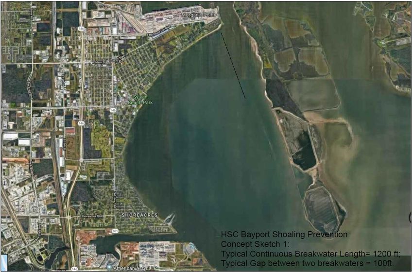
Sediment Training Options for the
         Bayport Flare in the Houston Ship
                     Channel
Design options for sediment and current training structures are investigated for the potential to reduce the
amount of sediment that settles in the Houston ship channel (HSC) and Bayport flare. The location of the
Bayport flare is shown in Figure 1. This reach of the HSC is exceptionally busy, and has required
substantial maintenance dredging due to ongoing shoaling.

                                   Figure 1: Bayport flare adjoining the HSC

Previous sediment modeling of vessel movements near the flare found that vessel induced fluid pressures
and sheer loads on the soil bed are eroding the soft surface material on the shallow bed surrounding the
HSC (1)(2). Eroded materials become suspended in the water column and carried by existing currents.
Previous circulation modeling has also shown that the residual bottom currents progress in a generally
counter-clockwise circulation pattern, with residual bottom current flowing South to North in the Channel
(Figure 2). Suspended sediments generally settle in locations with lower currents, such as the Bayport Flare
(circled in Figure 1). Modeling has also shown that vessel induced erosion generates the majority of the of
the shoaling material rather than other sources such as river sediments or shoreline erosion. The vessel
induced shear stresses that cause erosion and subsequent transport are larger and impact more area in the
reach along Atkinson Island. Historical dredging records indicate the Bayport Flare (circled in Figure 1) is
a major sink; it is a large, deep area where the velocity drops sufficiently for material to settle. Movement
of sinks within the flare are probably caused by turbidity maxima or salt wedge tip migration throughout
the year. These locations tend to be further downstream in the HSC in spring during high freshwater flows,
and are likely to be pushed further upstream along Atkinson Island during periods of high tides and lower
flows.
Figure 2 shows the bottom flow residual velocities in the area of interest (circled in red) without any current
or sediment training structures. There is a residual circulation in the shallow flats north of the Bayport flare
and west of the HSC. Ship wakes generated in the HSC dislodge material in these shallow flats, most of
which gets mobilized by the circulation. The reach is sufficiently busy that entrained sediments do not have
adequate low-energy time to settle in the shallow flats West of the channel. Entrained sediments continue
with the counter-clockwise circulation and are ultimately deposited in the deeper and lower energy Bayport
flare. Additionally, sediment coming down the river also gets entrained in this circulation and goes into
the flare instead of being flushed through the ship channel. Only a small percentage of suspended sediment
becomes entrained in the channel and flows Southward.

                            Figure 2: Bottom residual velocities w/o Training structures

The fundamental problem leading to the shoaling is believed to be the broad circulation pattern combined
with the large amount of traffic in the reach. Sediments are continuously suspended by passing ships, and
then carried with the circulating currents until they settle in the relatively quiescent deep sections the depth
of which are subsequently maintained by dredging. Prior modeling included assessment of two proposed
sediment-training structures (Figures 3 and 4). These chevron-shaped structures are intended to prevent
sediment entering the HSC as well as the Bayport flare, but are not believed to be effective because detailed
circulation modeling has shown these structures to have little or no impact on the broad circulation through
and North of the Flare. The proposed chevron structures may encourage greater shoaling because of reduced
bottom velocities in the dredged areas, but have no effect on the problematic circulation of extremely
sediment-rich water.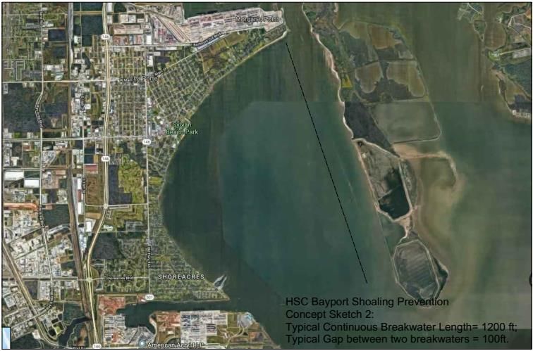
Figure 3: Bottom residual velocities with single chevron sediment training structure.

Figure 4: Bottom residual velocities with multiple chevron sediment training structures.

Two new solutions are proposed for detailed evaluation in Engineering Design, each of which is intended
to reduce the counterclockwise circulation. Figure 5 shows the less costly proposed solution, which is a
segmented breakwater that runs north-south from the northernmost part of the flats adjoining the HSC to
about 1/4th the way to the flare, Appendix A for cost details. This structure is intended to train the
downstream currents in a way that interrupts the large-scale counter-clockwise circulation such that
suspended sediments are carried Southward though the ship channel, rather than entering the large
circulation pattern. In addition to training the currents, the breakwaters are only slightly emergent, such that
wave energy can overtop the breakwaters, but neither the energy nor entrained sediments can return to the
ship channel. The breakwater segments are about 1,200 ft long, interrupted by a series of gaps of
approximately 100ft to allow small-boat navigation and environmental circulation. The low energy and
low current area behind the breakwater will also allow sediments generated in the upper part of the reach
to settle in the wedge-shaped area rather than into the ship channel or further downstream. This option is
the less costly of the two because it is relatively short, but it offers no settlement area for suspended
sediments South of the end of the breakwater. Detailed analysis should be performed to determine where
these suspended sediments are likely to be deposited after they are carried South in the new current
circulation pattern.

The second solution proposed is shown in Figure 6. A new breakwater is proposed from the Northernmost
part of the flats all the way down to the flare. The advantage of this more expensive solution is that the
entire flats region is sheltered from ship wakes and currents such that it becomes a sediment deposition
areas outside the ship channel. This solution is costlier as compared to the shorter breakwater, but is
expected to provide better sediment detainment at a known fixed location outside the ship channel.

                                       Figure 5: 1/4th Breakwater Concept
Figure 6: Extended Breakwater Concept

The preliminary design specifications for these breakwaters based on calculations in CEDAS are given in
Table 1. These calculations assume a structure slope of 1:3.

                             Table 1: Breakwater Design Specifications (CEDAS)

 Wave period                                          4.3 secs
 Armor unit weight                                    165 lb/ft3
 Wave height                                          4.6 ft
 Stability Coefficient                                1.2 (Trunk) & 1.1(Top)
 Layer Coefficient                                    1.02
 Porosity                                             38%
 COT of structure slope                               3
 Number of units comprising the layer thickness       2
 Single Armor Unit Weight                             11,100 lb
 Minimum crest width                                  6.0 ft
 Average layer thickness                              4.0 ft
 Average number of single armor units per unit        340/1,000 ft2
 surface area
 Single Armor Unit Weight (Top)                       1,235 lb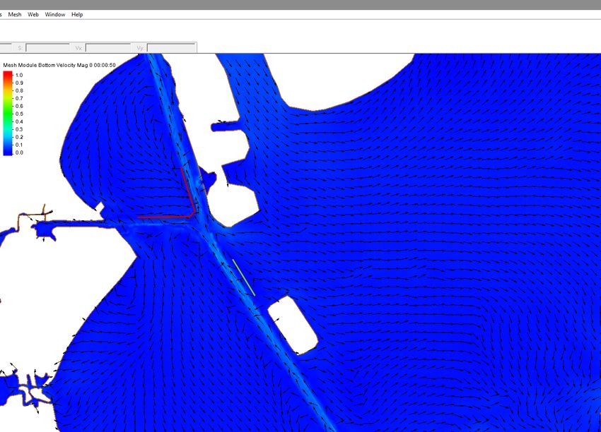
The proposed cross-section is the same for either the longer or shorter breakwater. The breakwater is to be
only marginally emergent (2ft above MSL). Emergence above the water surface is necessary to prevent a
serious navigation hazard for small craft, but it is to be only marginally emergent such that wave energy
and entrained sediments can pass over the breakwater out of the channel area.

The breakwater is to be fully armored on top and on the East side facing the ship channel, but the subaqueous
areas on the West side would be backed by a long gentle slope of dredge tailings, stabilized using living
shoreline techniques. Use of the tailings is less costly to construct because less rock armoring is required,
provides additional space for placement of dredge tailings, and provides additional shallow water habitat
for marine life. The low height was included in calculating the size of the rock armoring: the Van der Meer
reduction factor (3) has been calculated to be 0.87, and the size of the armor units shown in Table 1 has
been reduced to 87% of the value calculated using CEDAS.

REFERENCES:
   1. Tate, J. N., and R. C. Berger. 2006. Houston-Galveston Navigation Channels, Texas Project:
      Navigation Channel Sedimentation Study, Phase 1. ERDC/CHL TR-06-8. Vicksburg, MS: U.S.
      Army Engineer Research and Development Center, Coastal and Hydraulics Laboratory.

    2. Tate, J. N., R. C. Berger, and C. G. Ross. 2008. Houston-Galveston Navigation Channels, Texas
       Project, Navigation Channel Sedimentation Study, Phase 2. ERDC/CHL TR-08-8. Vicksburg, MS:
       U.S. Army Engineer Research and Development Center, Coastal and Hydraulics Laboratory.

    3. Van der Meer, J.W. (1990), Verification of Breakwater for berm breakwaters and low-crested
       structures, Delft Hydraulics Report H986/Q638, Delft, The Netherlands.
APPENDIX A
18 October 2018
Thomas White, PhD, PE, D.CE
HSC Sediment Attenuation Feature
Options and Costs
Per the team’s 11 September 2018 decision to compare costs between continuing additional dredging near
the Bayport Flare vs. a sediment attenuation feature, four options were examined to determine
construction costs.
Option #1 was proposed by ERDC and consists of the triangular section shown in red and a straight
section in green.
Lengths are 4858 yards for the triangle and 1817 yards for the straight section for a total length of 6675
yards.Option #2 was proposed by ERDC and consists of 3 triangular sections shown in white. Lengths are 2 x 3 x 877 = 5262 yards for a total length.
Short Option #3 has a total length of 2433 yards, with length of each segment = 1200ft and
typical gap of 100ft.
Long Option #4 has a total length of 7140 yards, with length of each segment = 1200ft and
typical gap of 100ft.
Cross Section

The following cross-section was taken from this Feasibility Study’s Engineering Appendix. In order to
be able to consistently compare the four options, the same cross-section was used for all four. Most
likely, this cross-section will produce an overestimate of cost, since the rock quantities are rather high,
which may be considered a contingency factor.

Cross-sectional areas of the rock and sediment portions were provided by one of the team members
working for the HPA, Chester Hedderman, P.E.

Rock = 322.6 ft2, and sediment = 1400 ft2, which includes 5ft of sediment used to vertically compress the
Bay floor.

                                               Cost Estimates

The Port’s price for rock, listed in the Draft Engineering Appendix is $ 91.55/ton. In order to convert this
price into a price per cubic yard, a conversion factor was computed as 166 lb/ft3 x 27 ft3/yd3 / 2000 lb/ton
= 2.24 ton/yd3.

The price of the rock portion of the cross-section is then 322.6 ft2 x $91.55/ton x 2.24 ton/yd3 / 9ft2/yd2 =
7351 $/yd.

For the sediment, the unit price is then 1400 ft2 x $20/yd3 / 9ft2/yd2 = 3112 $/yd.

Option #1 (large triangle plus straight section) is 6675yd x (7351 + 3112)$/yd = $69.8 million

Option #2 (three triangles) is 5262yd x (7351 + 3112)$/yd = $55.1 million

Option #3 (short segmented breakwater) is 2433yd x (7351 + 3112)$/yd = $25.5 million

Option #4 (long segmented breakwater) is 7140yd x (7351 + 3112)$/yd = $74.7 million
Caveats (reasons why these are likely to be overestimates of cost):
$20/yd3 is probably an overestimate of dredged sediment unit cost.
Gaps in the two TAMU options (#3 and #4) were ignored. (The breakwaters were assumed to be
continuous.)
The cross-section is probably overdesigned in terms of how much rock is used.
Final Step
It is out of the purview of H&H to estimate excess dredging quantities near the Bayport Flare. Other
disciplines should provide such estimates. The final step is to compare the attenuation feature’s
annualized cost to the excess dredging’s annual cost. If the ratio is low, then such a feature is worth
pursuing with modeling.You can also read