Seismic requirements for fire protection systems - Andrea BRIZZI - November, 7th 2012
←
→
Page content transcription
If your browser does not render page correctly, please read the page content below
Seismic requirements for fire
        protection systems
      Andrea BRIZZI – November, 7th 2012

1
Content

    1.   Scope
    2.   Reference standards
    3.   When (where) seismic requirements apply
    4.   Protection of sprinkler piping

2
Scope
Recommendations / requirements for the protection of
sprinkler systems against damage in areas subject to
earthquakes are intended to:
Improve the likelihood that the fire protection systems will remaining in
working condition after the earthquake;
Minimize potential water damage due to leakages from fire protection
systems.
3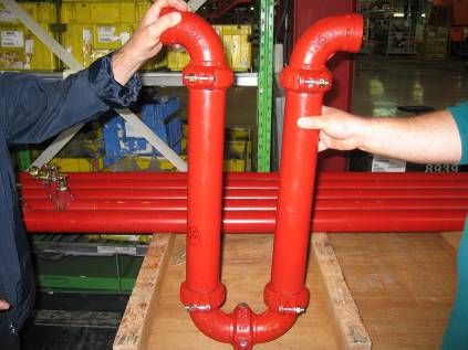
Reference standards
NFPA 13, 2013 (Sprinkler Systems), Paragraph 9.3
NFPA 20, 2013 (Fire Pumps), Paragraph 4.28
NFPA 22, 2008 (Water Tanks), Paragraphs 4.11.4, 5.3, 6.3
Factory Mutual Datasheet 2-8, 2010 (Earthquake Protection
for Water-Based Fire Protection Systems)
Guida Tecnica “Linee di Indirizzo per la Riduzione della
Vulnerabilità Sismica dell’Impiantistica Antincendio”,
Dicembre 2011, Ministero dell’Interno
The purpose of this presentation is a focus on
requirements for sprinkler systems in areas subject to
earthquakes, according to NFPA 13.
4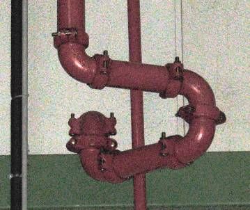
When (where) seismic requirements apply
NFPA standards do not specify where to provide seismic
protection geographically
Criteria to be considered:
Site hazardousness (pga);
Building characteristics;
Highly exposed locations (type of activity, high values, etc.);
New constructions / Existing constructions
New sprinkler systems / Existing sprinkler systems
5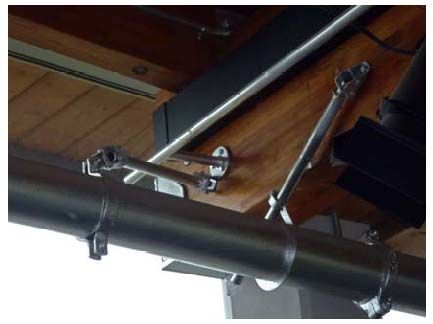
Protection of Sprinkler Piping

                        SEISMIC REQUIREMENTS:
                             2 OBJECTIVES

       MINIMIZE STRESSES IN PIPING                MINIMIZE DAMAGING
    Provide flexibility and clearances where   Keep piping fairly rigid, when
          building is expected to move       supported by a building component
                                                 expected to move as a unit

                     THE SYSTEM SHALL MOVE TOGETHER
                             WITH THE BUILDING

6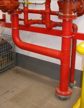
Protection of Sprinkler Piping
4 categories of requirements:
A. Flexible Joints and Clearances
Couplings – NFPA 13, Section 9.3.2
Seismic Separation Assembly – NFPA 13, Section 9.3.3
Clearance – NFPA 13, Section 9.3.4
B. Sway Bracing – NFPA 9.3.5
C. Restraints of Branch Lines – NFPA 9.3.6
D. Hangers Subject to Earthquakes – NFPA 9.3.7
Important: braces and restraints should comply with the obstruction
rules and should not constitute an obstruction to the sprinkler discharge
7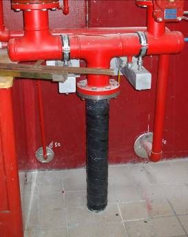
Flexible Couplings – NFPA 13, Section 9.3.2 Flexible couplings have to be provided in order to allow individual sections of piping to move differentially with the sections of the building to which are attached Flexible couplings are required on pipes >= 65 mm, unless specific requirements Flexible couplings shall be arranged to coincide with structural separations within a building If flexible couplings are provided more then required by the standard, then additional lateral sway bracings have to be provided to improve system stiffness. 8
Flexible Couplings – Risers (regardless of the size)
Greater than 2.1m: within 610mm of top and bottom
Between 0.9 and 2.1m: one flexible coupling
Less than 0.9m: no flexible couplings
Within 610mm above and below any further point of support
610mm
610mm 610mm
9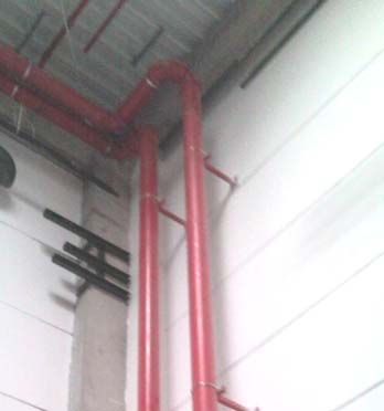
Flexible Couplings – Multistory Buildings
Within 305mm above and within 610mm below the floor. If
the FC is above the tie-in for the main supply for that floor,
a further FC shall be provided on the vertical portion of the
tie-in piping.
10Flexible Couplings – Concrete or Masonry Walls
On both sides of concrete or masonry walls within 305mm
of the wall surface, unless clearance is provided
Lack of clearance
Need for FC
11Flexible Couplings – Expansion Joints
Within 610mm of building expansion joints (usually a
bituminous fibre strip to separate blocks of concrete to
prevent cracking); on one side only.
12Flexible Couplings – Drops (regardless of pipe size)
Drops exceeding 4.6 m in length to portions of systems
supplying more then one sprinkler:
Within 610 mm of the top of the drop
Drops to hose lines, rack sprinklers, mezzanines, and
free-standing structures:
Within 610 mm of the top of the drop
Within 610 mm above the uppermost drop support attachment, where drop
supports are provided to the structure, rack or mezzanine;
Within 610 mm above the bottom of the drop, where no additional drop
support is provided
13Flexible Couplings – Drops
Drops to hose lines, rack sprinklers, mezzanines, and
free-standing structures
NOTE
1. Where racks are freestanding, that
is independent of the building
structure, their movement relative
to the ceiling can be considerably
greater than can be accommodated
by a single flexible coupling. In
these cases multiple flexible
couplings, flexible elbows or similar
provisions are needed. A
differential lateral movement of 5%
of the rack height can indeed be
expected
2. Storage racks should be designed
to resist lateral forces produced by
earthquakes.
14Flexible Joints
Paragraph 9.3.2.1 – Listed flexible pipe couplings joining grooved
end pipe shall be provided as ….
FLEXIBLE COUPLINGS
GROOVED COUPLINGS
RIGID COUPLINGS
NOT ALL THE GROOVED COUPLINGS ARE FLEXIBLE !!!!
NFPA 13 – A9.3.2: “Rigid-type” couplings that permit less than 1
degree of angular movement at the grooved connections are
not considered to be flexible couplings »
15Flexible Joints
The term flexible coupling is defined as a coupling or fitting that
allows axial displacement, rotation, and at least 1 degree on
angular movement of the pipe without inducing harm on the pipe
Flexible coupling Rigid coupling
16Seismic Separation Assembly – NFPA 13, Section 9.3.3
Buildings, in seismic areas shall be structurally separated
once they reach a specific length and/or square footage.
Where a building is separated, no part of the structure is
connected at that point, therefore the two parts move
independently of each other.
Separations can be found where there are 2 columns grid,
very close to each other, and two structural beams very
close to each other.
Seismic Separation Assembly vs expansion joint.
Movement admitted by separation are much greater than
ones admitted by expansion joint.
17Seismic Separation Assembly
In correspondence of seismic separation, regardless of pipe size, an
approved seismic separation assembly shall be provided.
It consists of an assembly of fittings, pipe and couplings that permits
movements in all direction
Flexible fittings and couplings
18Seismic Separation Assembly
Flexible Piping
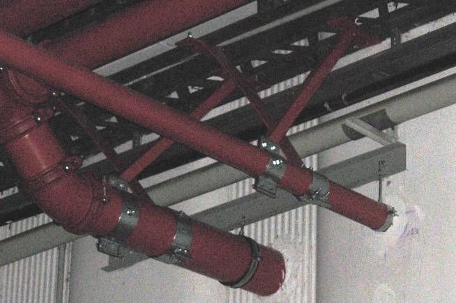
19Seismic Separation Assembly
Bracing of seismic separation assembly:
The seismic separation assembly should include a four-way brace
upstream and downstream within 1.8 m of the seismic separation
assembly. Bracing should not be attached to the seismic separation
assembly. Between SS and
seismic assembly
NO SUPPORTS!!
FC missing!!!
Supports welded to
the pipe!!!
BREAK!!!
Seismic
separation
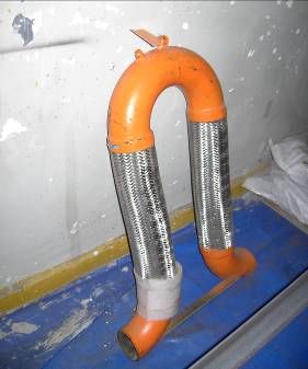
20Seismic Separation Assembly
NOT FLEXIBLE !!!
21Clearance – NFPA 13, Section 9.3.4
Clearance should be provided around all piping extending
through walls, floors, platforms and foundations.
Size of the holes:
50 mm larger than the pipe, for pipe sizes 25 mm to 90 mm
100 mm larger than the pipe, for pipe sizes 100 mm and larger
Main Exceptions
Clearance provided by pipe sleeves (same specifications as per holes)
No clearance is required for piping passing through frangible construction
(gypsum board or equally frangible material)
No clearance is required if flexible couplings are located within 305 mm of
each side of a wall, floor, platform or foundations
22Clearance
Where required, the clearance should be filled with only
weak-frangible material (sand, mortar…) which can break
if stressed during an earthquake
Clearance from structural members, not used to support
the piping, should be at least 50 mm
23Clearance
MISTAKES !!!
2 SOLUTIONS: FC or CLEARANCE
24Sway Bracing – NFPA 13, Section 9.3.5
Sway bracing is provided to prevent excessive movement of
system piping (horizontal and vertical). Shifting of large pipe
as a result of earthquake motion has led to the pull-out of
hangers and fracture of fittings. With some exceptions,
bracing is required for the following:
1. Top of the system riser,
2. All feed and cross mains regardless of size,
3. Branch lines 65 mm (2½”) in diameter and larger (lateral bracing only).
Branch line piping 50 mm in diameter and smaller is
considered capable of considerable movement without
damage.
25Sway Bracing
Three types of Sway Braces:
LATERAL sway braces – Preventing movements in an axis
perpendicular to pipe)
LONGITUDINAL sway braces – Preventing movements in an axis
parallel to pipe)
FOUR-WAY braces – Intended to resist differential movement of the
piping system in all horizontal directions (typically used on vertical pipe
/ risers)
26Sway Bracing
Lateral Sway Brace Longitudinal Sway Brace
Four-Way Bracing
Lateral and Longitudinal Sway Braces Tension-only Bracing System
27Lateral Sway Bracing – Requirements
On all feed and cross mains regardless of size.
On branch lines and other piping with a diameter >= 65mm.
Not required for 65 mm starter piece that is the first section of pipe on
branch lines from a cross main provided it does not exceed 3.6 m in
length.
The spacing should never exceed 12.2 m; it might have to be reduced
according to size and schedule of the pipe being braced and the load
of the piping in the zone of influence (NFPA 13, Tables 9.3.5.5.2(a)).
The distance between the last brace and the end of the pipe should
not exceed 1.8 m.
The last length of pipe at the end of a feed or cross main should be
provided with a lateral brace.
28Lateral Sway Bracing – Exceptions
Requirements for Lateral Sway Bracing do not apply when:
Pipes are individually supported by rods less than 150 mm long,
measured between the top of the pipe and the point of attachment to
the building structure. This exception is not accepted by FM Global.
U-type hooks of the wraparound type or those U-type hooks arranged
to keep the pipe tight to the underside of the structural element are
permitted to be used to satisfy the requirements for lateral sway
bracing, provided the legs are bent out at least 30 degrees from the
vertical and the maximum length of each leg and the rod size satisfies
the conditions of Tables 9.3.5.11.8. This exception is admitted by FM
Global only for branch lines that need sway bracing; for feed and cross
mains U-bolt hangers may be used while U-type hangers, including
wraparound type shall not be used.
29Lateral Sway Bracing – Example
Note: The 65 mm starter piece on branch lines does not require
lateral sway bracing as its length isUnnecessary Flexible Couplings and Lateral Sway
Bracing
Where flexible couplings are installed on mains other than as required in
Section 9.3.2, lateral brace should be provided within 610 mm of every
other coupling but not more than 12.2 m on center
The intent of this is to prevent excessive movement of the mains,
possibly resulting in “accordion” effect. This additional bracing is not
required where rigid-type mechanical couplings are used
This requirement applies only to horizontal mains and branch lines
required to be braced as mains. It does not apply to other branch lines or
to vertical piping such as risers
Conclusion: As a general rule, rigid mechanical couplings
should be used throughout except where flexible couplings
are recommended
31Lateral Brace as Longitudinal Brace
Lateral braces are allowed to act as longitudinal braces if
they are within 610 mm of the center line of the piping braced
longitudinally and the lateral brace is on a pipe of equal or
greater size than the pipe being braced longitudinally
32Longitudinal Sway Bracing – Requirements
On all feed and cross mains regardless of size.
The spacing should never exceed 24.4 m on center.
The distance between the last brace and the end of the pipe should
not exceed 12.2 m.
Longitudinal braces are allowed to act as lateral braces if they are
within 610 mm of the center line of the piping braced laterally
33Sway Bracing – Example
EXAMPLE
LONG. SB
LAT. SB
HANGER
CLEARANCE
34Sway Bracing of Risers – Requirements
A four-way brace should be provided at top of risers
exceeding 0.9 m in length.
Distance between four-way braces for risers should not
exceed 7.6 m.
When a four-way brace is attached on the horizontal
piping it should be within 610 mm of the centreline of the
riser.
No four-way brace are required on riser nipples even if
they exceed 1 m in length (riser nipples = vertical pieces
of pipe connecting mains to branch lines at different,
usually higher, elevations).
Four-way bracing is not required where risers penetrate
intermediate floors in multi-storey buildings where the
clearance does not exceed the limits.
35Sway Bracing of Risers – Example
NO 4 way Brace!!
4 way
Wrong Brace
FC!!!
new
FC
Remove FC
36Examples of sprinkler systems with lateral,
longitudinal and four-way braces
37Sway Brace Design and Installation
Sway braces should be designed to withstand forces in tension and
compression. Tension-only bracing systems are accepted by NFPA
where listed for this service and installed according listing limitations.
They are not accepted by FM Global.
Sway braces should be UL listed or FM approved. The horizontal load
applied to the brace should not exceed the maximum allowable load
provided in the listing for the weakest component of the brace.
Bracing shall be attached directly to the system pipe.
C-clamps should not be used to attach braces to the building
structure.
The type of fasteners used to secure bracing assembly to the
structure should be limited to listed devices or those reported in NFPA
13, Fig 9.3.5.12.1.
38Restraint of Branch Lines – NFPA 13, Section 9.3.6
Restraint is required for all branch lines that are not
otherwise required to be laterally braced:
The end sprinkler on a branch line should be restrained against
excessive vertical and lateral movement.
Branch lines longer than 8 m might require additional restraints
(spacing should follow the limits of NFPA 13, Tables 9.3.6.4).
Restraint is NOT required for branch lines supported by
rods less than 150 mm long measured between the top of
the pipe and the point of attachment to the building
structure.
40Restraint of Branch Lines
Restraint should be provided by use of one of
the following:
A listed sway brace assembly
A wraparound U-hook in accordance with NFPA 13,
9.3.5.5.10
200 kg wire installed at least 45 degrees from the
vertical plane and anchored on both sides of the pipe. Wrap around U-hook
Wire used for restraint should be located within 610 mm
of a hanger. That hanger should be of a type that
resists upward movement of a branch line.
A hanger not less than 45 from vertical installed within
152 mm (6”) of the vertical hanger arranged for restraint
against upward movement (see picture below).
Branch line restraint
41Hangers Subject to Earthquakes – NFPA 13,
Section 9.3.7
Where seismic protection is provided, C-type clamps used
to attach hangers to the building structure should be
equipped with a restraining strap.
The restraining strap should be listed or not less than
1.6 mm thick and not less than 25 mm wide for pipe
diameters 200 mm or less and 2 mm thick and not less
than 32 mm wide for pipe diameters greater than 200 mm.
42THANK YOU FOR
YOUR ATTENTION
Andrea BRIZZI
Deputy Regional Manager
AXA MATRIX Risk Consultants
Via della Moscova, 3 - 20121 Milano
office: +39 02636965203
mobile: +39 3407126367
andrea.brizzi@axa-matrixrc.comYou can also read