Subaru
 Rotated Mount
V-band Turbo Kit
←
→
Page content transcription
If your browser does not render page correctly, please read the page content below
Subaru Rotated Mount V-band Turbo Kit
The goal of AMS is to provide the highest quality, best performing
products available. By utilizing research and development, and
rigorous testing programs AMS will never compromise the quality
or performance of our products. In addition, AMS will only
provide the finest customer service offering only parts and advice
that are in the best interests of the customer. AMS was built on a
foundation of integrity. This is who we are; this is what you can
count on.

A vehicle modified by the use of performance parts may not meet
the legal requirements for use on public roads. Federal and state
laws prohibit the removal, modification, or rendering inoperative
of any part or element of design affecting emissions or safety on
motor vehicles used for transporting persons or property on public
streets or highways. Use or installation of performance parts may
adversely affect the drivability and reliability of your vehicle, and
may also affect or eliminate your insurance coverage, factory
warranty, and/or new OEM part warranty. Performance parts are
sold as-is without any warranty of any type. There is no warranty
stated or implied due to the stresses placed on your vehicle by
performance parts and our inability to monitor their use, tuning, or
modification.

These instructions are provided as a guide only as there are many
variables that cannot be accounted for concerning your particular
vehicle, including but not limited to model year differences, model
differences, the presence of non-OEM parts, and modifications that
may already be or were previously installed. A basic knowledge of
automotive parts and systems is helpful but a better understanding
of the parts and systems on your particular vehicle may be
required.

If you have any questions or issues at any time during the
installation of your AMS product(s) please call us for technical
assistance. The AMS tech line can be reached during business
hours at 847-709-0530 for AMS products only.
up-pipe support bracket                       plastic vacuum fittings

“A” (left) and “B” (right) oil fittings            turbo oil feed line

        TiAL v-band clamps                small, medium, and large 2-bolt gaskets

    8mm auxiliary coolant lines           10mm turbo coolant lines with heat sleeves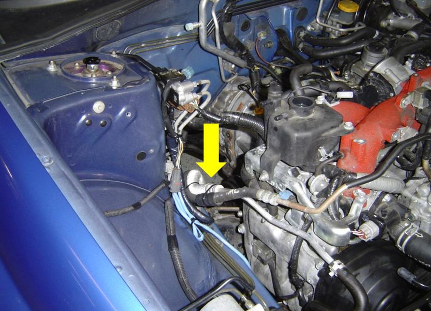
***As these instructions apply to ’02-’07 WRX/STi AND ‘08+ STi they are designed to be
   used as a guide only. You may have to make additional or alternate modifications for
                            proper fitment during your install.***

Specialty Tools Required: High temperature thread sealant, o2 sensor socket, anti-seize
compound, silicone spray, high temperature copper RTV silicone.

Installation Instructions:

1) Drain oil and coolant from engine.

2) Remove the following parts according to the manufacturer’s recommendations. Some parts
    will be re-installed later.
    a) Factory top-mount intercooler with Y-pipe, bypass valve, and recirculation tube.
    b) Passenger-side top-mount intercooler bracket.
    c) Air filter box.
    d) Coolant expansion tank lines and clamps.
    e) Turbo inlet hose. NOTE: It might be easier to cut this in half to remove it but BE
         CAREFUL NOT TO CUT THE FACTORY FUEL LINES UNDERNEATH!
    f) Downpipe, cat/test pipe, and secondary o2 sensor.
    g) Turbocharger oil feed line, oil return line, coolant lines, mounting bolts, and then turbo.
    h) Up-pipe to engine brackets (2), mounting bolts (2), and then up-pipe.
    i) Primary o2 sensor.
    j) OPTIONAL: Brackets on the passenger-side strut tower that hold the boost control
         solenoid and harness connectors. Tuck the wires away and zip-tie in place.
    k) Unbolt coolant expansion tank and move it out of the way, remove power steering line
         brackets circled below, and then gently bend the rear part of the hard lines down
         (arrows). Use zip-ties to keep them in place as shown.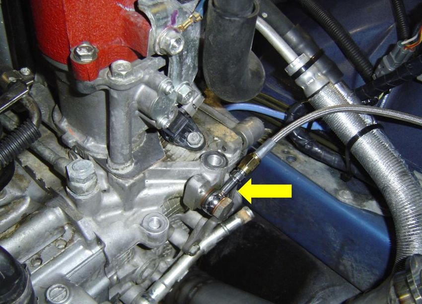
3) Install AMS rotated up-pipe.
   a) Remove the 2 transmission bolts (arrows) and mount the up-pipe support bracket as
      shown, re-using the factory bolts. On ‘08+ cars there is an additional bracket that must
      also be installed at this time, see the last 2 pages of these instructions for reference.
      NOTE: On some vehicles there is a large piece of casting on the transmission (area
      circled) that may need to be ground down about ¼” for wastegate clearance.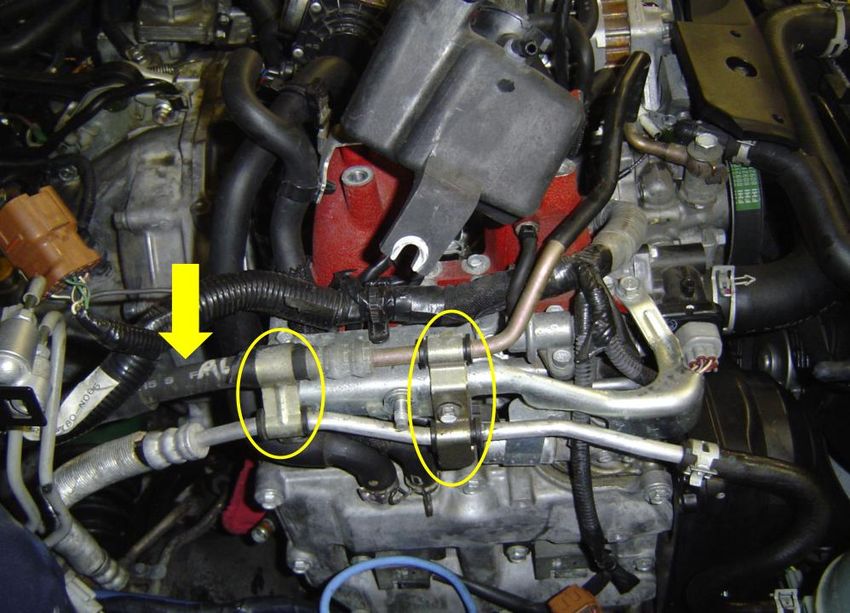
b) Align 2-bolt up-pipe flange on headers with the mounting tab facing the up-pipe support
       bracket installed in the previous step, and then loosely assemble using the provided
       gasket and hardware with a serrated lock washer on the bolt side. NOTE: A factory
       gasket is provided but if you have aftermarket headers it may be a restriction. Either re-
       use your gasket or obtain a new one from your header manufacturer.
    c) Tighten header to up-pipe bolts first, then tighten support bracket bolt.

4) Install turbo oil feed line and fittings.
    a) Install engine-side oil feed fittings “A”, “B”, or “C” (see packing list) depending on your
       particular vehicle. Position the fitting so it points towards the passenger side of the engine
       bay and slightly up.
       i) A: Re-use your factory M10 oil feed bolt and install the 30° banjo fitting with a copper
           M10 washer on either side.

        ii)  B: First, install the supplied M12 banjo bolt into the factory oil feed location with a
             copper M12 washer on either side (arrows). Second, use the black cap to block off
             the unused part of the factory oil feed hard line. Finally, use a very small amount of
             thread sealant on the 1/8” NPT threads of the 45° fitting and install it into the banjo
             bolt (circled). NOTE: NPT threads have a slight taper for a leak-free seal. OVER-
             TIGHTENING WILL DAMAGE THE THREADS AND CAUSE AN OIL LEAK WHICH
             WILL RESULT IN TURBO FAILURE!
        iii) C: Re-use your factory M12 oil feed bolt and install the straight banjo fitting with a
             copper M12 washer (from “B”) on either side.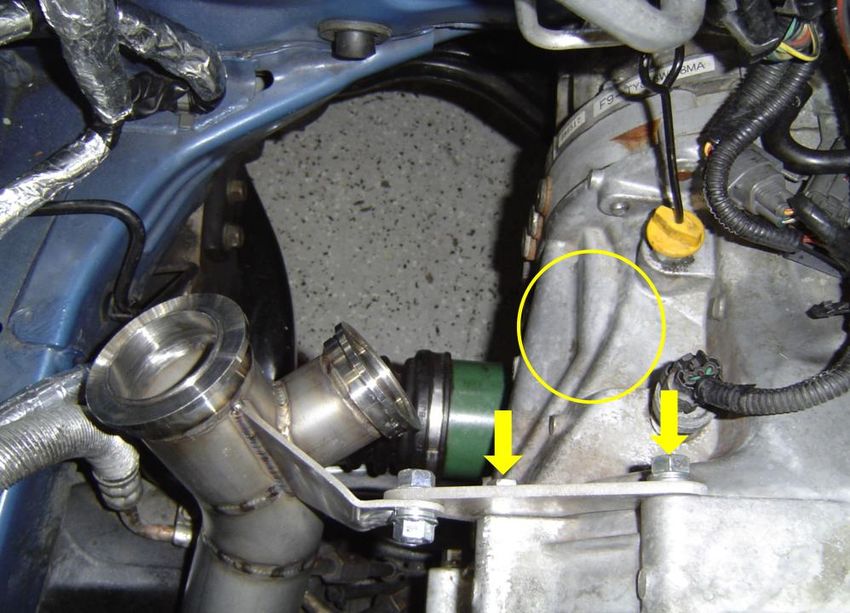
b) Loosely thread the straight side of the oil feed line onto the oil feed fitting installed in the
       previous step. This will allow you to properly position the other end on the turbo.

5) Install TiAL wastegate and dump tube.
    a) Attach dump tube to wastegate outlet with small TiAL v-band clamp and then tighten,
       making sure the clamp doesn’t interfere with mounting the wastegate on the up-pipe.
    b) Position wastegate on up-pipe (make sure valve seat is in place) with dump tube pointing
       down towards the ground, then mount on up-pipe with large TiAL v-band clamp but
       LEAVE IT LOOSE so it can be clocked for downpipe clearance.
    c) Install air fittings (with bolts and washers) and rotate the barbed end towards the front of
       the car. You may or may not use them depending on how you’re going to control boost.

6) Cut A/C drain hose (circled) to allow clearance for downpipe.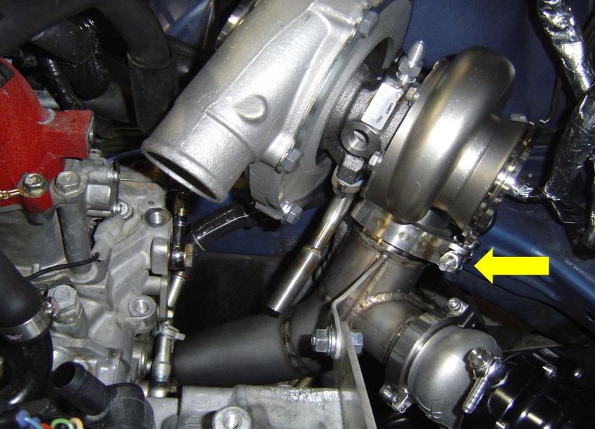
7) Install the turbocharger. First prepare the turbo by installing the oil return tube and coolant
    fittings, which may require removing the turbine housing. Install the oil return tube using the
    provided gasket and bolts, pointing towards the engine. Install the coolant fittings with a
    copper washer on either side, pointing down and slightly away from the turbine housing.
    a) Place the turbo on the up-pipe with the TiAL v-band clamp positioned as shown (arrow).
          LEAVE THE CLAMP LOOSE so it can be rotated for downpipe clearance and proper
          exhaust alignment.

8) Install turbo oil return line.
    a) Slide clamps over oil return hose, then slide hose over the turbo-side oil return tube.
       Keep pushing the hose over the tube until you have enough room to slide it back down
       over the engine-side oil return tube. Use silicone spray on the inside of the hose to help
       slide it on the tubes.
    b) Push hose down over engine-side oil return tube until it evenly overlaps on each side. If
       the tubes aren’t aligned then you will need to clock the center section by loosening the 6
       10mm bolts (2 are circled) that hold it to the turbine housing and then rotating the turbo
       into place. Make sure to tighten them back down when you’re done, but not too much
       since they’re M6 bolts. Check that the turbo wheels still spin freely, and then tighten oil
       return hose clamps (arrows).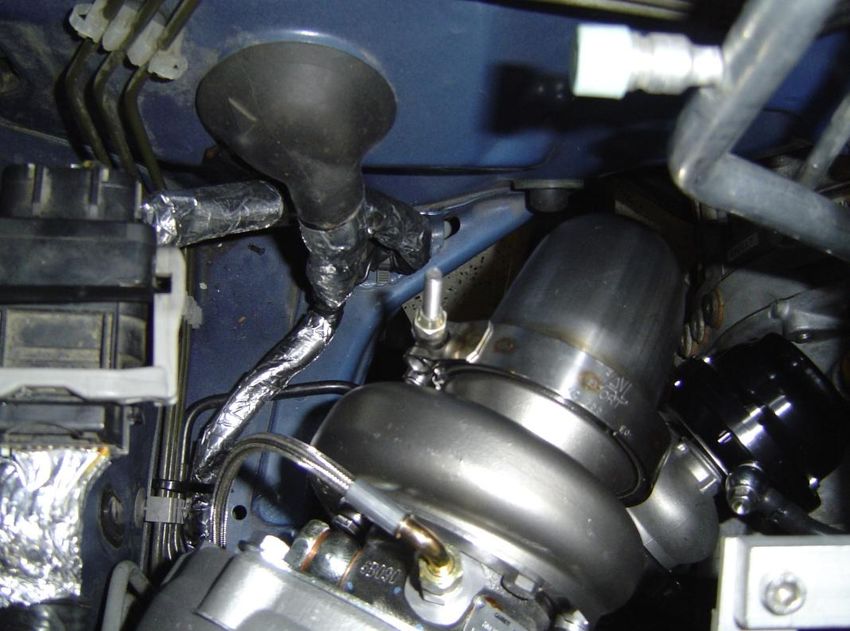
9) Install turbo coolant lines.
    a) Slide one piece of heat sleeve and 2 clamps over the short turbo coolant hose, then push
       the line on the rear turbo coolant barb.
    b) Slide the other end of the coolant hose over the lower engine coolant tube, near the oil
       feed fitting. Tighten both hose clamps.

    c) Slide the other piece of heat sleeve and 2 clamps over the long turbo coolant hose, and
       then push the line on the front turbo coolant barb.
    d) Slide the other end of the coolant hose over the upper engine coolant tube, located on
       the coolant expansion tank. Tighten both clamps, then slide the heat sleeve as close to
       the turbo as possible.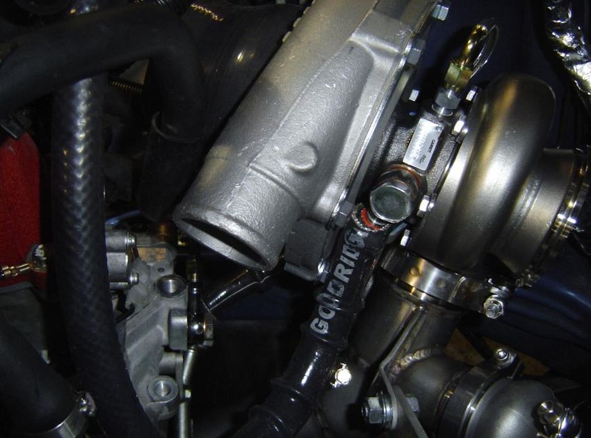
10) Install the 90° end of the oil feed line on the turbo, routing it around the passenger side.
    Tighten both sides of the line. NOTE: BE CAREFUL NOT TO OVER-TIGHTEN AND STRIP
    THE ALUMINUM OIL FITTINGS ON EITHER SIDE OF THE LINE!

11) Install AMS downpipe.
    a) Install o2 plug in downpipe if you’re NOT going to use a wideband sensor.
    b) Attach v-band side of downpipe to turbine housing, but LEAVE THE CLAMP LOOSE to
       allow for proper cat/test pipe fitment.
12) Install AMS cat/test pipe.
a) Loosely hang the pipe on the transmission bracket (arrow) with the factory hardware.
b) Align the front and rear 2-bolt flanges with the AMS downpipe and your cat-back exhaust,
using the aluminum gasket on the front. Use high temperature copper RTV on both sides
of the aluminum gasket and loosely bolt together with supplied M10 hardware.
c) Install wideband o2 sensor into the downpipe (if used), and secondary o2 sensor into the
cat/test pipe.
d) Make sure everything is properly aligned and there’s clearance around the exhaust pipes
and flanges and then tighten the up-pipe, downpipe, and wastegate v-band clamps,
cat/test pipe bolts, and trans bracket bolt. Make sure that none of the pipes are being
forced in any direction due to misalignment. NOTE: V-band flanges allow a wide range of
adjustment for precise fitment. A small rotation at the up-pipe to turbo v-band connection
can make a big difference when trying to connect the downpipe to the cat/test pipe, and
especially the cat/test pipe to your cat-back exhaust.
e) Double-check the clearance around the exhaust pipes and make adjustments if
necessary. Use insulation tape on any of the wires, harnesses, or hoses that will be close
to the turbo kit up-pipe, turbine housing, and downpipe. Connect o2 sensor(s). NOTE:
Keep wires away from all exhaust pipes!
13) Install AMS turbo intake pipes.
a) Remove front passenger-side wheel and move front part of inner fender well liner out of
the way.
b) Attach air filter to the side closer to the bracket on the lower pipe, then install the 3”
straight coupler on the other end. Tighten both hose clamps (arrows).c) Use existing stud and nut shown and loosely hang cold-air intake pipe. d) Attach 4” – 3” silicone reducer on turbo inlet and tighten large clamp. e) Slide remaining clamps over silicone reducer on turbo and silicone coupler on cold-air pipe. f) Install upper intake pipe into silicone reducer and coupler. If equipped, first install vacuum barbs using high temperature thread sealant on the brass fittings and clean any resulting debris from the inside of the pipe. NOTE: NPT threads have a slight taper for a leak-free seal. OVER-TIGHTENING WILL DAMAGE THE THREADS!
g) Connect intake vacuum barbs to PCV system lines that were connected to the factory
      turbo inlet pipe, using the silicone hoses and a small zip-tie at each connection. A typical
      install will have the larger lines going to the valve cover breathers (plastic T-fitting) and
      crankcase breather (plastic straight fitting), with the smaller line going to the purge
      solenoid mounted on the intake manifold.
   h) OPTIONS: If you ordered the intake pipe with a provision for a MAF sensor and/or
      bypass valve, install those parts at this time.
      i) Use anti-seize on the factory bolts and re-install MAF sensor.
      ii) Route AMS silicone re-circulating hose going from the turbo intake pipe, under the
          intake manifold, to the factory bypass valve location (yellow line). Re-install bypass
          valve and tighten both hose clamps.

   i)   Make sure all turbo intake pipes, hoses, and lines are routed properly and then tighten all
        the clamps and double-check all your connections. Bolt cold-air pipe all the way down,
        then re-install inner fender well liner and wheel.

14) Replace factory coolant expansion tank lines with 8mm lines and clamps provided. Use a
   couple zip-ties to keep them in place (yellow lines).
15) Install AMS silicone turbo outlet hose. You will need to clock the compressor cover to align
the hose with your intercooler piping by disconnecting the turbo intake pipe and then
loosening the 6 13mm bolts on the cover. Clock the cover, re-connect the intake pipe, and
snug the bolts back down. NOTE: Only loosen the bolts as much as it takes to be able to
rotate the compressor cover. Misalignment of the cover to the backing plate will cause
damage to turbo compressor wheel blades when the bolts are tightened back down!
TOP MOUNT 30R FRONT MOUNT 30R/35R (yellow line)
16) Re-install your intercooler and piping.
17) DOUBLE-CHECK EVERYTHING! Make sure oil and coolant line connections are secure,
wires and lines are away and protected from extreme heat sources, hose clamps, exhaust v-
band clamps, and bolts, are tight, etc.
18) Replace oil filter and fill engine with oil and coolant. Start vehicle and CHECK FOR LEAKS!
Let the car warm up and bleed the cooling system, and check the oil level.
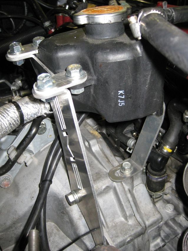
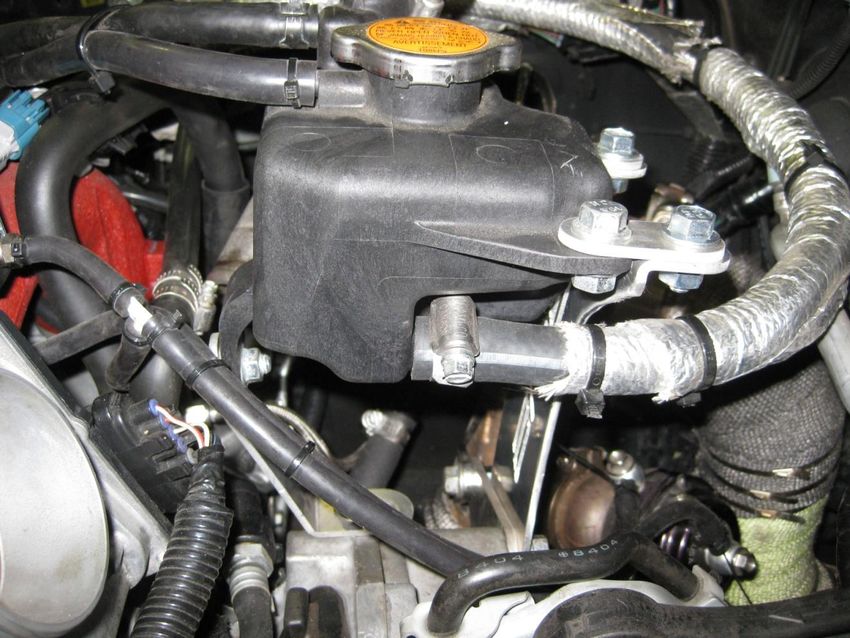
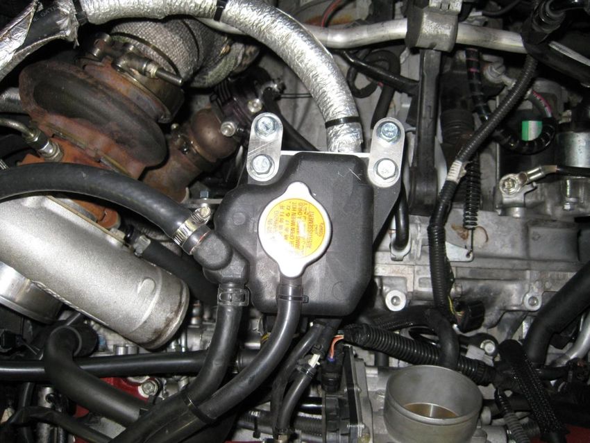
19) GET TUNED!!!‘08+ STi Coolant Reservoir Relocation Top View Side View 1
Side View 2

Install the brackets as shown with the large “AMS” one being stacked behind the turbo kit up-pipe
support bracket on the transmission. Make sure to keep ALL lines away from any sources of high
heat and/or abrasion using protective heat sleeve where necessary.
You can also read