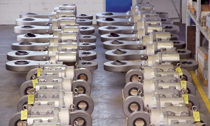
LISEGA - Standard Supports 2020
←
→
Page content transcription
If your browser does not render page correctly, please read the page content below

Standard Supports 2020
Standard Supports 2020
Date of issue: June 2015

The LISEGA product program covers all components required
for the implementation of modern concepts in the support of
pipe systems.

These components correspond to the LISEGA standardization
philosophy and are organized in a modular system with load
and attachment compatibility.

Containing the complete product program, this catalog is in
full compliance with LICAD, the LISEGA pipe support design
program.

The catalog and LICAD can be downloaded from www.lisega.de.

LISEGA reserves the right to introduce revisions in the interest
of further technical development.
Standard Supports 2020

Performance with System

Customers and their suppliers depend on
each other for mutual success. We at LISEGA
want to show ourselves to be partners of
value to our customers with a comprehen-
sive and effective performance package.
We are prepared to provide top performance
day in and day out. Our goal is customer
satisfaction and only if we achieve that
objective are we satisfied too – that’s where
our motivation is coming from.

Right from the beginning, some five decades
ago, we have concentrated exclusively on
pipe supports, thoroughly and comprehen-
sively.

The quality and efficient utilization of our
products are just as important to us as
our reliability and low application costs.                                          (from left to right)
                                                                                    Dr. Ekkehard Heinrichs,
The basis is a well-engineered product program of more than 12,000 stand-           Chief Technical Officer
ardized support components forming a clearly arranged functional modular            Hans-Herlof Hardtke,
                                                                                    Chairman of Supervisory Board
system. The resulting efficiency, and in particular by using our LICAD design
                                                                                    Dr. Georg Friberg,
software, provides additional savings in costs both in planning and installation.
                                                                                    Chief Executive Officer
                                                                                    Hans-Heiner Eddelbüttel,
Confident that we have a committed work force to support us, the LISEGA             Chief Finance Officer
management invests all its energy into satisfying customer requirements.
For this, and for our mutual pleasure in seeking success, people at LISEGA are
working together with our customers, goal-orientated and highly motivated by
performance with system.

LISEGA

    Hans-Herlof Hardtke                    Dr. Georg Friberg
Zeven, Germany
Headquarters

                                                                          Kodak, TN, USA

             Bondoufle, France

                                              Shanghai, China

             Al-Jubail, Saudi Arabia

                                                                      Netherton, England

                                       Wittenburg, Germany
                                       (LISEGA affiliate for fasteners)
Overall contents
 Detailed information on contents in the individual sections                  Product Group

                                       Technical specifications
                                                                                  0
                                       Constant hangers, constant supports
                                                                                  1
                                       Spring hangers, spring supports
                                                                                  2
                                                                                  3
                                       Snubbers, rigid struts, viscoelastic
                                       dampers, energy absorbers,
                                       dynamic clamps

                                       Pipe clamps, clamp bases,
                                       pipe connecting parts                      4
                                       Roller bearings, pipe saddles,
                                       cryogenic clamp bases                      5
                                       Threaded connecting elements
                                                                                  6
                                       Structural attachments, trapezes,
                                       clamps, slide plates                       7
            Plug-in
LICAD®
               and
            Libraries
                                       LISEGA software tools for
                                       planning and design                        8
                                       Supplementary services,
                                       engineering, field service                 9
Product Group 1                                           Product Group 2
Constant hangers, constant supports, types 11, 12, 19     Spring hangers, spring supports, types 21, 22, 28, 29

Product Group 3                                           Product Group 4
Snubbers, energy absorbers, rigid struts, viscoelastic    Pipe clamps, clamp bases, pipe connecting parts,
dampers, dynamic clamps, types 30-39                      types 41-46, 48-49

Product Group 5                                           Product Group 6
Roller bearings, pipe saddles, cryogenic clamp bases,     Threaded connecting elements, types 60-67
types 51-58

Product Group 7                                           Product Group 8
Structural attachments, trapezes, clamps, slide plates,   LISEGA software tools for planning and design
types 73-79

Product Group 9
Supplementary services, engineering, field service
0

                               Technical
                           specifications
Technical
specifications
                 Product     0
                 group
Technical
specifications
Contents

1. Standard Supports, requirements and definition . . . . . . . . . . . . . . 0.1
                                                                                              Page
                                                                                                         0
                                                                                                         PRODUCT
                                                                                                         GROUP      0
2. LISEGA Standard Supports . . . . . . . . . . . . . . . . . . . . . . . . . . . . . . 0.1
3. LISEGA Modular System . . . . . . . . . . . . . . . . . . . . . . . . . . . . . . . 0.2
3.1 User benefits . . . . . . . . . . . . . . . . . . . . . . . . . . . . . . . . . . . . . . . . 0.2        1
3.2 Functionality . . . . . . . . . . . . . . . . . . . . . . . . . . . . . . . . . . . . . . . . 0.2

                                                                                                             2
3.3 Product groups . . . . . . . . . . . . . . . . . . . . . . . . . . . . . . . . . . . . . 0.2
3.4 Load groups . . . . . . . . . . . . . . . . . . . . . . . . . . . . . . . . . . . . . . . . . 0.2
3.5 Travel ranges . . . . . . . . . . . . . . . . . . . . . . . . . . . . . . . . . . . . . . . . 0.3
3.6 Product groups . . . . . . . . . . . . . . . . . . . . . . . . . . . . . . . . . . . . . . . 0.3
3.7 Modular System for load and connection compatibility . . . . . . . . . . . 0.4
4. Permissible loads . . . . . . . . . . . . . . . . . . . . . . . . . . . . . . . . . . . . 0.5
                                                                                                             3
4.1 Statically and dynamically loaded components . . . . . . . . . . . . . . . . 0.5
4.2 Product group 4 . . . . . . . . . . . . . . . . . . . . . . . . . . . . . . . . . . . . . . 0.5
4.3 Product group 5 . . . . . . . . . . . . . . . . . . . . . . . . . . . . . . . . . . . . . . 0.5          4
4.4 Load groups . . . . . . . . . . . . . . . . . . . . . . . . . . . . . . . . . . . . . . . . 0.6

                                                                                                             5
5. Type designation system . . . . . . . . . . . . . . . . . . . . . . . . . . . . . . . . 0.7
6. Standards and codes . . . . . . . . . . . . . . . . . . . . . . . . . . . . . . . . . . 0.9
7. Materials . . . . . . . . . . . . . . . . . . . . . . . . . . . . . . . . . . . . . . . . . . . 0.9

                                                                                                             6
8. Welding . . . . . . . . . . . . . . . . . . . . . . . . . . . . . . . . . . . . . . . . . . 0.10
9. Surface protection against corrosion . . . . . . . . . . . . . . . . . . . . . 0.10
9.1 Standard corrosion protection . . . . . . . . . . . . . . . . . . . . . . . . . . . 0.11
9.2 Increased corrosion protection . . . . . . . . . . . . . . . . . . . . . . . . . . . 0.12
9.3 Hot dip galvanized surface treatment . . . . . . . . . . . . . . . . . . . . . . 0.13
10. Operational behavior . . . . . . . . . . . . . . . . . . . . . . . . . . . . . . . . . 0.14
                                                                                                             7
11. Connection dimensions . . . . . . . . . . . . . . . . . . . . . . . . . . . . . . . 0.15
12. Quality Management and IMS . . . . . . . . . . . . . . . . . . . . . . . . . . . 0.16
13. Suitability tests, types tests . . . . . . . . . . . . . . . . . . . . . . . . . . . . 0.17
14. Standard versions and increased requirements . . . . . . . . . . . . . . . 0.18
                                                                                                             8
                                                                                                             9
15. Form of shipment . . . . . . . . . . . . . . . . . . . . . . . . . . . . . . . . . . . . 0.19
16. Warranty . . . . . . . . . . . . . . . . . . . . . . . . . . . . . . . . . . . . . . . . . . 0.19
17. Technical modifications . . . . . . . . . . . . . . . . . . . . . . . . . . . . . . . . 0.19
                                                                                                              0.0
Technical
specification
The products outlined in 1. Standard Supports, definition 2. LISEGA Standard Supports
this catalog - Standard
Supports 2020 - are fully
and requirements
2.1 Scope
in line with the latest At LISEGA, standard supports form the basis
developments in support
1.1 Requirements
For the support of industrial piping systems of a comprehensive performance package. A
technology and satisfy complete product program of more than 12,000
the use of standard supports is regarded as
general requirements for standardized components covers all support
well-proven, up-to-date technology.
plant installation at the situations, operational loads, temperatures and
highest level. For the
Only a high level of standardization can satisfy the travel ranges normally experienced in piping
general design of LISEGA
demand for technically superior and at the same systems in industrial plant construction:
standard supports, uni-
time economical support components. The com-
form criteria are applied.
plex requirements for modern pipe supports are: 650°C operating temperature for pipe
They are described in the clamps and clamp bases
following Technical spec- 400kN nominal load for all mainly
reliable functioning
ifications and are binding statically loaded components
maintenance-free operation
for the contents of this 1000kN nominal load for rigid struts
quick delivery
catalog. Componentrelated and standard snubbers
low component prices
features are outlined in the 5000kN design load for large-bore
computerized design systems
corresponding sections of snubbers
easy installation
the product groups and in 900mm travel range for constant hangers
favorable performance weight ratio
the type data sheets 400mm travel range for spring hangers
Unless expressly agreed 1.2 Definition
2.2 Design features
otherwise, the stipulations Standard supports must fulfill the following Specially developed components are available
in the catalog Standard criteria:
for the various support functions. Fundamental
Supports 2020 apply to design principles were taken into consideration
all our shipments. component shapes are uniform and
designed to make the optimum use in the design and construction of the compo-
of material nents:
components are compatible regarding
dimensions and load capacity symmetrical design shapes
components are cataloged and clearly compact installation dimensions
designated via an identification system special, reliable functional principles
components are manufactured in series extra-wide adjustment ranges
production fully compatible load ranges and
components comply with the approved connection dimensions
standards and international codes integrated installation aids
the functional capacity, suitability and du-
rability of the components is well proven Moreover, LISEGA hangers feature only one upper
components are certified and approved for connection point. Due to this, along with compact
use by independent certification bodies and symmetrical design shapes, load distribution
free of imposed moments on the connections is
The relevant codes for pipe supports in German ensured and easy installation made possible. The
and European plant construction (power sta- operating position of the moving parts (hangers,
tions), the DIN EN 13480-T3 and VGB Guideline supports and snubbers) can be read directly off
R 510 L, require the preferential use of standard a linear travel indicator.
supports and define the criteria as follows:
Load adjustment of the constant hangers and
“Standard Supports are pipe support components supports can be carried out at all times, even
in which the design in form and dimensions, as in the installed condition. Hangers and sup-
well as the design data regarding loads, are spec- ports can be blocked in any travel position.
ified, verified and cataloged and where the com-
ponents are manufactured according to defined,
reproducible processes, e.g. series production”.
0.12.3 Principle of the optimum design
For the design and arrangement of support
components, optimum coverage of the specific
support function is the decisive factor. So only
one design is required for each function, namely,
The cumulative benefits from this result in reli-
able project processing at competitive prices
with superior component quality. In addition,
the user also benefits from cost reductions in
labor-intensive sectors such as support engineer-
0
The economic principle:
= with the least possible
effort, achieving the
maximum possible benefit
the optimum one for the purpose. The project ing (design) and onsite installation. The assem-
engineer is no longer forced to choose from a bly procedure for the pipe systems can also be = Total Cost Minimum/TCM
range of alternative solutions. streamlined by first installing the supports, then
mounting the piping directly into them.
This not only facilitates application but also
increases safety. In addition it is a prerequisite 3.2 Functionality
for the logical implementation of standardized The standardization of components at LISEGA
construction according to the modular system. is specifically directed toward their systematic First install the supports,
interaction as support configurations. To this then mounting the pipes!
There’s only ONE best solution! end, load and travel ranges as well as the ge-
ometry of the connections are harmonized. The
3. The LISEGA Modular System LISEGA standard support program has been
developed in this fashion as a fully functional
3.1 User benefits and effective modular system. The individual
The cost of pipe supports is a major factor in components therein form modules and guarantee
the total cost of a pipe system. The cost of the load compatibility. This enables a wide range of Product Groups
supports is the accumulated total arising from combinations to produce tailor-made support + load groups
the individual costs of: configurations as required. The comprehensive + travel ranges
selection of components enables adaptation + connection compatibility
project management (processing) widely to differing support situations and appli-
design and engineering work cation conditions. = Modular System
use of material (components) and
installation and assembly work 3.3 Product groups
The standardized components are divided into
Moreover, the pipe supports are almost always 7 product groups according to task and function
critical for the commissioning deadlines and can, (see standardized components table p. 0.3 and
through delays in delivery, cause incalculable diagram on p. 0.4).
extra costs.
3.4 Load groups Modular System
The goal of the LISEGA product strategy is to To ensure uniform loading in component + CAD design
achieve optimum user benefits for customers at combinations the product groups are arranged + IT Logistics System
the lowest cost, following the economic principle. throughout according to clearly classified static
and dynamic load groups (see p. 0.5 and p. 0.6). = High-Tech Application
The LISEGA modular system provides the corre-
sponding basis. The standardization of compo-
nents is the decisive prerequisite for:
rational series production
favorable performance/weight ratios
consistently high product quality
ready availability from stock
our special LICAD® design software
0.23.6 Product groups
standard components
product group type component
Metric or UNC according to Within a load group (nominal load) all components
region of application. Constant 11 Constant hangers
feature uniform load limits and safety margins. 1 hangers & 12-14 Constant hangers, multi-cell
Within a load group the connection dimensions supports 16 Constant supports, multi-cell
of the components (thread and bolt diameters) 17 Servo hangers
are uniform and compatible with the components 18 Constant hangers, low profile
in other product groups. 19 Constant supports, low profile
19 Angulating const. supp., low profile
As different components can only be combined 71 Brackets for constant hangers
with each other within the same load group the 79 Constant hanger trapezes
stresses on a load chain are consistent through- Spring 20 Angulating spring supports
out, whereby the clamps are selected in each
2 hangers 21 Spring hangers
22 Heavy duty spring hangers
case according to the relevant temperature and 25 Spring hangers, seated
isolation thickness of the pipe system. 26 Heavy duty spr. hang. (seated)
27 Sway braces
The incorrect combination of parts from different 28 Heavy duty spring supports
load groups is thus avoided. 29 Spring supports
72 Base plates
3.5 Travel ranges 79 Spring hanger trapezes
Dynamic 30 Snubbers
3.5.1 Constant and spring hanger 3 components 31 Large bore snubbers
32 Energy absorbers
travel ranges 33 Installation extensions
Moving components such as constant and spring 34 Dynamic pipe clamps
hangers are split into travel ranges correspond- 35 Weld-on brackets
ing to the usable spring travel of the standard 36-38 Dynamic pipe clamps
39 Rigid struts
springs used. The relevant travel range in each
3D Viscoelastic dampers
case is designated in the type description by the 3L Shear lugs
4th digit in the following table. 3R Pipe whip restraints
Pipe 40 U-bolts
4 connecting 41 Weld-on lugs
components 42-44 Horizontal clamps
For spring hangers and constant hangers spring hangers
supports (Product Group 2) 45,46,48 Riser clamps
the springs are pre-stressed
travel range type travel range type 49 Clamp bases, lift-off restraints
[mm] designation [mm]
designation 77 Connection plates
to approx. 1/3 of their nominal
load. This results in the initial 0 - 75 1. .1 .. 0 - 50 2. .1 .. Pipe 51 Cylinder roller bearings
load. 0 - 150 1. .2 .. 0 - 100 2. .2 .. 5 bearings 52 Double taper roller bearings
0 - 300 1. .3 .. 0 - 200 2. .3 .. and saddle 53 Double cylinder roller bearings
0 - 450 1. .4 .. 0 - 300 2. .4 .. components, 54 Weld-on pipe saddles
0 - 600 1. .5 .. 0 - 400 2. .5 .. cryogenic 54 Pipe saddle with pipe clamps
0 - 750 1. .6 .. clamp bases 55 Lift-off restraints
0 - 900 1. .7 .. 56 Cryogenic clamp bases
57 Cryogenic axial stops
3.5.2 Snubber travel ranges 57 Weld-on pipe shoes
The LISEGA snubbers are grouped into standard 58 Stanchions
stroke ranges denoted by the 4th digit of the Threaded 60 Eye nuts
type designation as in the following table. 6 connecting 61 Clevises
elements 62 Turnbuckles
63 Hexagon nuts
snubbers 64 Rod couplings
type 65 Tie rods L/R
stroke [mm] type designation 66 Tie rods
150 30 3. .2 .. 67 Threaded rods / stud bolts
300 30 3. .3 .. Structural 70 Sliding components
400 30 3. .4 .. 7 attachment 73 Weld-on clevises
500 30 3. .5 .. elements 74 Weld-on plates with sph. washers
600 30 3. .6 .. 75 Weld-on eye nuts
750 30 3. .7 .. 76 Beam adapters
100 30/31 3. .8 .. 78 Beam clamps
200 30/31 3. .9 .. 79 Trapezes
0.33.7 Modular system
for load and connection
compatibility
0
Constant hangers,
constant supports
Pipe clamps,
clamp bases,
1 Spring hangers,
pipe connections spring supports
Structural attachments,
4 Cryogenics,
stanchions, roller bearings,
2 Snubbers,
rigid struts, energy absorbers,
trapezes, beam adapters, viscoelastic dampers,
pipe saddles
7 5 3
slide plates dynamic clamps
LISEGA Software
Connecting
Tools for Planning
components
8 6
and Design
Load and
connection compatibility
M 1
10 0.3
M 10 2
10 C 0.6
M 10 5
12 D 1.2
M 12 0
12 1 2.5
M 12 0
16 2 5.0
M 16 0 0
20 3 10 .
M 20 00
M
24 4 20.
24 00
M
30 5 40.
33 00
M
36 6 60.
40 00
M
42 7 80.
48 45 . 0 0
M
8 100 0
56x 50 0 .0
9 6
M 4 60 0
1 0
64 .0
M x4
1 200 0
68 70 0 0 .0
2 4
M x4 70 0
2
.00
72 3 0
M x4 30 0
80x 80 0 .0
4 4 400
90 0
nominal load kN
5
load group
thread
Ø bolts
0.4Cold load:
The cold load is the load deter-
4. Permissible loads As these components are generally used as safety
mined by the pipe system calcula-
devices for emergencies, load case HZ or level
tions for the support point in shut 4.1 Statically and dynamically loaded C (ASME) are taken as the maximum occasion-
down condition. ally occurring load condition. In any case, the
components
requirements set forth by the project engineer
Set load (blocking load): For permissible loads we distinguish between
The set or blocking load is the responsibly apply.
load at which the spring or con-
statically and dynamically loaded components.
stant hanger is set and blocked. The components in product groups 1, 2, 4, 5, 6,
The set load is made up of the and 7 are, according to their function, loaded in
4.2 Product group 4
cold load and the dead weight of For product group 4 (pipe connections), a cor-
the components suspended from
only one direction (static or quasi static) and are
responding overlapping area in the load groups
the spring or constant hanger. In viewed as statically determined components.
part, blanket dead weights are is taken into account, due to the wide temper-
already calculated into the cold ature-dependent range of different loads. Data
loads. These must be taken into
4.1.1 Static components
on the permissible loads for pipe-connecting
account when designing the hang- The nominal load is used to denote the load
er arrangement. components under consideration of the respec-
group. For the statically determined components
tive operating temperatures can be taken from
Hot load (operating load):
in product groups 1, 2, 6 and 7 the nominal
the individual selection tables.
The hot or operating load is the load corresponds to the max. set load of spring
load acting on the support point elements such as spring hangers. The max. op-
during normal operation. For spring The permissible operating loads for long-term
hangers it is made up of the set
erating load (load case H) is, in the event of use operation (load case H (under normal conditions),
load and the force resulting from as a rigid support, considerably higher than the normal load, level A) are shown here. On higher
spring travel multiplied by spring nominal load and is adapted to the load capacity short-term loading (e.g. hydrostatic tests) no
rate. For constant hangers the hot
load corresponds to the set load.
of the connection thread. This also includes spring permanent deformation is caused.
hangers and constant hangers in blocked con-
Hydrostatic test load: dition, whereby for cold loads in pressure tests
The hydrostatic test load is the
The permissible loads in load cases HZ (emergen-
load acting on the support during
(short duration) the emergency loads (load case cy (occasionally occurring operating conditions),
pressure testing, in general at HZ) can be exploited. level C) and HS (faulted condition, level D) depend
80°C.
on the codes to be complied with.
Pickling (and clean) load: 4.1.2 Dynamic components
The pickling load is the load dis- For dynamically loaded components the nom- examples
tributed from the supports points inal load corresponds at the same time to the load case HZ load case HS
during pickling of the pipe system, code (emergency) (faulted condition)
in general at 200°C. operating load for load case H (under normal
ASME section III, NF H x 1.5 H x 1.6
conditions) or load A/B (ASME). RCCM H x 1.33 H x 1.6
MSS SP-58 H x 1.2 no data
DIN EN 13480 H x 1.2 no data
VGB-R 510 L H x 1.15 H x 1.5
KTA 3205.3 H x 1.15 H x 1.5
dynamically determined statically determined components 4.3 Product group 5
components product group 3 product groups 1, 2, 6, 7 The components in product group 5, clamp bases
load nominal Ø connect- load nominal Ø connect- spanner connecting for cold pipe systems, low temperature systems
group load [kN] ing bolt group load [kN] ing bolt width bolt (cryogenic) as well as roller bearings and pipe
– – – C 0.31 M10 16 10 saddles, are regarded as static after determined
– – – D 0.62 M10 16 10
but are not considered to be part of the modular
1 3 10 1 1.25 M12 18 12
2 4 10 2 2.5 M12 18 12 system with regard to the load group. As they are
3 8 12 3 5.0 M16 24 16 more comparable with components in secondary
4 18 15 4 10 M20 30 20 steelwork with respect to loading, they form a
5 46 20 5 20 M24 36 24 separate group. The nominal load here corre-
6 100 30 6 40 M30 46 33 sponds to the max. operating load according to
7 200 50 7 60 M36 55 40 load case H. For product group 5 see also 4.4.3,
8 350 60 8 80 M42 65 45
9
p. 0.6.
550 70 9 100 M48 75 50
10 1000 100 10 160 M56x4 85 60
20 2000 120 20 200 M64x4 95 70 For components qualified acc. to KTA 3205 the
30 3000 140 30 240 M68x4 100 70 following applies: HZ = H x 1.5; HS = H x 1.7
40 4000 160 40 300 M72x4 105 80
50 5000 180 50 400 M80x4 115 90
0.54.4 Load tables
The permissible loads of the components are
arranged in the form of a matrix (ordered acc.
to load groups and load cases) in the following
LISEGA load tables. The definition of the load
Div. 1, Subsection NF and KTA 3205. The load
table applies uniformly to all components in the
LISEGA modular system and to other LISEGA
components scheduled for use with standard
Max. operating load for spring
and constant hanger corre-
sponding to max. load on
main springs. The load group
0
allocation does not apply to
cases are in line with DIN EN 13480-T3, VGB-R components such as special designs. types 18/19.
510 L, ASME B31.1, MSS SP-58, ASME section III,
Permissible loads acc. to
4.4.1 Max. permissible load [kN] for statically determined components design criteria for US standard
“MSS SP-58” (ASME B 31.1 /
normal operating conditions
occas. occurring operating conditions B 31.3).
load nom. load H/normal upset HZ/emergency faulted condition HS/faulted
All loads are included here
group [kN]
80°C 150°C 80°C 150°C 80°C 150°C that can possibly occur during
C 0.31 0.7 0.8 0.7 1.1 1.0 1.4 1.3 conventional operation of the
D 0.62 1.7 2.5 2.2 3.3 2.9 4.3 3.8 plant, including startup and
1 1.25 2.8 4.2 3.7 5.6 5.0 7.2 6.4 shutdown, weight tolerances,
2 2.5 4.4 6.7 6.0 9 8.0 13.3 12 and hydrostatic tests.
3 5.0 8.5 11.3 10.1 15 13.4 22.2 20
Loads falling outside conven-
4 10.0 14 23.3 20.9 31 27.8 41 37 tional operation are includ-
5 20.0 27 34 30 46 41 61 55 ed here, according to the
6 40.0 43 56 50 74 66 96 86 regulations in each case, also
7 60.0 63 83 74 108 97 140 126 hydrostatic tests. Subsequent
8 80.0 85 114 102 150 135 195 175 inspection of the whole support
arrangement is strongly advised.
9 100 112 151 135 196 176 255 230
10 160 178 222 199 295 265 381 343 Due to the loads specified the
20 200 215 297 266 395 355 512 461 yield stress of the components
30 240 270 340 305 452 406 585 526 can be reached. At all events
40 300 320 380 340 505 450 650 585 replacement is recommended.
50 400 400 490 440 650 585 840 755
All dynamic stresses possibly
resulting from plant operation
4.4.2 Max. permissible loads [kN] for dynamically are included here including pres-
sure shock forces from valve
determined components, product group 3 operations or possibly from
normal operating conditions operating basis earthquakes
occas. occurring operating conditions faulted condition
(0.B.E.).
load (FN)/upset level A/B level C level D
group 80°C 150°C 80°C 150°C 80°C 150°C All dynamic stresses beyond
1 3 2.9 4.0 3.8 5.2 5.0 conventional operation and
2
possibly safety shutdown
4 3.9 5.3 5.1 6.9 6.7
3 8 7.5 10.6 9.7 13.7 12.6 earthquakes (S.S.E.) are included
here. Subsequent inspection of
4 18 16.5 23.9 22.0 31 28.5
the whole support arrangement
5 46 44.0 61 58.5 77 74.5 is strongly recommended.
6 100 94.5 141 127 180 162
7 200 175 267 239 336 301 For the dynamic loads specified
8 350 339 472 423 655 588 the yield stress of the compo-
9 550 535 735 715 935 910 nents can be reached. At all
events replacement is strongly
10 1000 937 1335 1236 1740 1612
recommended.
20 2000 1900 2660 2520 3440 3270
30 3000 2850 4000 3800 5160 4900 Load groups 1 and 2 are
40 4000 3800 5320 5050 6880 6530 compatible regarding load
50 5000 4750 6650 6310 8600 8150 and connections, whereby load
group 1 refers to the smallest
snubber and load group 2 to
the corresponding rigid struts
4.4.3 Max. permissible loads 4.4.4 Max. permissible loads and weld-on brackets.
for roller bearings in product group 5 for snubbers
permissible loads [kN] permissible loads [kN]
normal operating conditions 4 8 16 35 60 120 3D .. .. -D 2.5 5 10 20 30 40 60 80 100
occas. occur. operat. cond. 5.5 11 22 47 80 160 3D .. .. -L 5.0 10 15 25 40 50
0.65. Type designations PG 1 Constant hangers and supports PG 3 Dynamic components
(continued) (continued)
All components can be identified via coded
type designations. 6 digits contain all the 2nd digit 3rd digit 4th digit 5th digit 6th digit 2nd digit 3rd digit 4th digit 5th digit 6th digit
information required for description of the constant load group travel field of production pipe diameter field of production
standard design. hanger [kN] range [mm] application series design load group [kN] application series
8= CH short D=M10 1=75 1,2= standard 7=2007 6= dynamic Pipe diameter standard 1-3= 1 x
The type designation system is the prerequi- 1=M12 2=150 5,6= clamps 2=to 500°C 4-5= 2 x
site for the use of modern IT and enables the 3=M16 with T0=1016 3=to 560°C U-bolt
unrestricted integration of the LISEGA modular 4=M20 U-bolt T1=1067 4=to 600°C
system into current CAD programs. 9= C-support, 5=M24 1,2= standard 6=with high 7= dynamic T2=1118 Strap
The LISEGA type designations can be decoded constant 7=M36 3,4= standard 7=with with strap T4=1219 6=to 350°C 7-8= 2 x
support, 8=M42 angulating PTFE-SE* 7=to 500°C Strap
by way of the following tables. short 9=M48 constant support 8=to 560°C
5,6= support 9=to 600°C
9= rigid 2=4 Middle installation 3-4=
The 1st digit describes the product group (PG) constant support
struts 3=8 dimension in mm/100 standard
7,8=
5=46
PG 3 =
Dynamic components constant support
7=200
PG 4 =
Pipe connecting components 8=350
PG 5 =
Pipe bearings and saddle PG 2 Spring hangers and supports 9=550
components, cryogenic clamp bases 0=1000
PG 6 = Threaded connecting elements 2nd digit 3rd digit 4th digit 5th digit 6th digit L= shear lugs 3rd to 6th digit corresponds to clamp type
PG 7 = Structural attachment elements spring load group travel field of production
hanger [kN] range [mm] application series
2nd digit 3rd + 4th digit 5th digit 6th digit
The digits 2 – 6 designate the further charac- 0= angulating C=M10 1= 50 1= standard 4=1994
spring support D=M10 2=100 5= 6=with high design load [kN] [mm] [mm]
design for increased requirements (5th or 6th for 2=M12 4=300 2= telescopable temp. SE* D= viscous- 03=2.5 40=40 3=30 3=30
digit) is described on p. 0.18. type 20 3=M16 5=400 spring support 7=with elastic 05=5 50=50 4=40 4=40
1= suspended 4=M20 9 = Ext. 6= 9=1999 15=15 80=80
7= sway brace 6=M30 & type 27 1=1991 20=20 H1=100
7= extension 7=M36 & type 29 25=25
for type 27 8=M42
.. .. ..-D = depend .. .. ..-L = limit
9= spr. support 9=M48
PG 1 Constant hangers and supports
2= heavy SH 1=M56x4 1= 50 1= standard 9=1999
2nd digit 3rd digit 4th digit 5th digit 6th digit suspended 2=M64x4 2=100 5=
load travel field of production seated 4=M72x4 2= standard pipe-connecting components
design group range [mm] application series 8= heavy 5=M80X4 6= temp. SE*
D=M10 3=300 5= 9=2009 1= weld-on D9= LGD 1=standard for straight
lug 29= LG2 pipes max.
3=M16
4=M20
6=750
7=900
PG 3 Dynamic components 39= LG3 insulation
5=M24 49= LG4 thickness
6=M30 2nd digit 3rd digit 4th digit 5th digit 6th digit 59= LG5 in mm
7=M36 load travel field of production 69= LG6 1=10
8=M42 design group [kN] range [mm] application series 79= LG7 2=100
9=M48 0= hydr. 1=3 2=150 1= standard 2=2002 01=21.3 02=26.9 1=standard for pipe
2= CH 2 x 8 LG10 1,3 = standard 5=1985 snubber 2=4 3=300 5=
absorber 6=100 9=200 11=114.3 13=133.0 thickn.
4= CH 4 x 8 LG40 3= extension 7=200 14=139.7 16=159.0 in mm
coupled 9 LG50 8=350 17=168.3 19=193.7 3,4=10
6= heavy con. 8 160kN 2=150mm 2= coupled 2 x 6=with high 9=550 22=219.1 24=244.5 5,6=100
support 9 200kN 3=300mm temp. SE* 0=1000 horiz. clamp 26=267.0 27=273.0 standard depen-
8 240kN 3= coupled 3 x 7=with 1= hydr. 2=2000 8=100 2= 1-hole 32=323.9 36=355.6 1=to 350°C ding on
9 300kN PTFE-SE* snubber 3=3000 9=200 2= 2-hole 37=368.0 41=406.4 2=to 500°C Load
8 320kN 4= coupled 4 x 9=without large 4=4000 3= 3-hole 42=419.0 46=457.2 3=to 560°C Group
9 400kN SE* bore 5=5000 4= with 51=508.0 56=558.8 4=to 600°C and
7= servo 5=M24 2=150 1= standard 5=1985 9=550 U-bolt 61=609.6 66=660.4 5=to 650°C design
hanger 6=M30 3=300 5= 9=1989 6= box-sh. T2=1118 T3=1168
49=18 09=1000 8=1988 for shear lugs T4=1219 7=to 500°C
*SE= sliding element 8=to 560°C
59=46 20=2000 8= box-sh
69=100 for trunnions 0=special material
0.7PG 4 Pipe clamps, clamp bases and PG 6 Connecting components PG 7 Structural attachments
pipe-connecting components (continued) and trapezes
2nd digit 3rd + 4th digit 5th digit 6th digit 2nd digit 3rd + 4th digit 5th digit 6th digit 2nd digit 3rd digit 4th digit 5th digit 6th digit
pipe diameter field of production field of production load group field of production
design [mm] application series design load group application series design [kN] function application series
9= clamp 01=21.3 02=26.9 standard 1= low 0= eye nut D9= M10-0.62kN 1= standard 2=1982 0= sliding Width Length 1= welded 1=
base 03=33.7 04=42.4 1=to 350°C 2= middle 1= clevis 29= M12-2.50kN 5= 8=1978 2=100 2=100 up to 180°C
07=73.0 08=76.1 3=to 560°C welded buckle 49= M20-10.0kN 9=1999 3=150 3=150
09=88.9 10=108.0 4=to 600°C 4= med., 4= rod 59= M24-20.0kN 4=200 4=200 4=
11=114.3 13=133.0 5=to 650°C welded coupling 69= M30-40.0kN 6=300 rectangular,
14=139.7 16=159.0 5= high, 3= hex. nut 79= M36-60.0kN 2= standard 3=1993 7=390 up to 350°C
17=168.3 19=193.7 99= M48-100kN 5= 08=Ø 85 17=Ø 170 2,3= bolted up to 180°C
32=323.9 36=355.6 7=to 500°C 20= M64x4-200kN 10=Ø 100 20=Ø 200 5= round,
37=368.0 41=406.4 8=to 560°C 30= M68x4-240kN up to 350°C
42=419.0 46=457.2 40= M72x4-300kN
51=508.0 56=558.8 50= M80x4-400kN 1= support C…9= 2=150 6= standard 1= single
61=609.6 66=660.4 bearing for Load Group 3=300 8=
71=711.2 76=762.0 6= tie rod R/R
81=812.8 86=863.6
2=M12 1=not 5= 6=750
0= U-bolt 91=914.4 97=965.2 1= S235JR 8= threaded rod
T0=1016 T1=1067 3= 1.4301 standard 4=M20 2= 500mm (7=900)
T2=1118 T3=1168 5=M24 3=1000mm 1= support 8=160kN 2= coupled
T4=1219 6= S235JR 6=M30 4=1500mm bearing 9=200kN 2x
8= 1.4301 7=M36 5=2000mm for heavy 8=240kN 3= coupled
9= lift-off 00= lift-off 0= lift-off 1-5= 8=M42 6=2500mm constant 9=300kN 3x
restraint for restraint restraint compon. 9=M48 7=3000mm hanger
8=320kN 4= coupled
clamp base size 10=M56x4 9=400kN 4x
Length
20=M64x4 2= base plate D…9= 1, 2, 3, 9= 2= standard 8= 1978
not
30=M68x4 stand- for spring Load Group dep. on 7=
and cryogenic clamp bases 50=M80x4 3= weld-on D…50= 0
Load 1= standard 2= 1982
clevis Load Group Group 9 5= 9= 1989
load group field of production Type designation 4= weld-on
design pipe diameter Ø application series plate
1= cyl. roller bear. 04= 4kN 1= standard 9=1989 1 2 3 4 5 6 5= weld-on
2= doub.tap.roll.bear. 08= 8kN 2= movable Production series/travel/variant eye plate
3= doub. cyl. roll. 12= 120kN laterally
bear. 16= 16kN Field of application/travel 6= beam D…4= size 2= beam 1= 2001
adapters adapter &
5= lift-off restraint 35= 35kN Travel range/pipe Ø/function & combi-
for roll. bear. 60= 60kN bolts
Load gr./pipe Ø/thread Ø nations
4= pipe saddle 01= 21.3mm 1= without C…2= size 1= 6= vertical
with pipe 02= 26.9mm pipe clamps Design cantilever connection
clamps, 03= 33.7mm 2,3= with Product Group (PG) 7= horizontal
weld-on 05= 48.3mm pipe clamps connection
saddles 06= 60.3mm 00=lift-off restraints 1...4= size
07= 73.0mm Examples
6= cryogenic 08= 76.1mm Length: Insulation 8= beam clamp 2..7= Load Group 1= standard 1= 1991
clamp base 09= 88.9mm 3=150mm thickness 1 1 5 3 1 5 9= constant 3 to 6 digits correspond to
rd th
7= cryogenic 10=108.0mm 5=300mm in mm 1985 hanger trapezes single hangers in each case (see PG1)
axial stop 11=114.3mm 7=500mm 0=25
13=133.0mm Standard design 9= spring 3rd to 5th digits correspond to 1= welded
8=750mm 1=40
14=139.7mm 2=50 Travel range 3/0-300mm hanger single hangers in each case (see PG2) unit
16=159.0mm 3=80 trapezes 9= with
Load gr. 5/FN = 20kN
17=168.3mm 4=100 individual
Individual design supports
19=193.7mm 5=130
22=219.1mm 6=150 Constant hanger 9= rigid C…4= 2,3= 3= standard 7=
24=244.5mm 7=180 trapezes Load Group depending 7= 9= U-profile,
2…9=
27=273.0mm 9=250 4 9 5 1 8 5 Load Group type centric
6= pipe bearing 32=323.9mm 9= pipe 1= pipe High design, welded
36=355.6mm connection
with cold bearing with bearing 13CrMo4-5, increased requirements
block 37=368.0mm cold block 2…20= 0
LG9 4=
41=406.4mm Pipe diameter 508mm Load Group U-profile
A= weld-on 1= Standard 1= out of
42=419.0mm Clamp base 7= connecting 3rd to 6th digit correspond to the clamps
bearing T-section
46=457.2mm Pipe connection plates to be coupled
2= out of
51=508.0mm
U-section
56=558.8mm
8= pipe 61=609.6mm 1= rigid 1,2=for 4 4 6 1 4 8
supports 66=660.4mm pipe str. pipes 3 9 6 2 5 4 Strap clamp for heavy loads
71=711.2mm supports 3,4=for Standard design
2= pipe elbows Material 10CrMo9-10 standard design
76=762.0mm
81=812.8mm supports, R
DA Medium length 2500mm Pipe diameter 609.6mm
91=914.4mm adjustable 5,6=for Load group 6/FN = 100kN Horizontal clamp, U-bolt or strap
97=965.2mm pipe elbows Rigid strut
R
1.5 DA
Pipe connection 0.8Worldwide coverage of 6. Standards and codes
recognized standards
In design, in stress and load calculations, as well The material characteristics upon which all design
as in production, the relevant European and other calculations are based are taken from the relevant
international standards are taken into account. standards and technical codes.
the following codes apply:
DIN EN 13480-T3 Metallic industrial pipe systems Europe
VGB-R 510 L Standard supports Germany
KTA 3205.1/2/3 Nuclear regulations Germany
AD-Merkblätter Pressure vessels working group Germany
RCC-M Specifications for pipe supports France
MSS SP-58 Pipe supports – material and design USA
MSS SP-69 Pipe supports – application USA
ANSI ASME B31.1 / B31.3 Pressure piping systems USA
ASME section III Div.I - NF Supports for nuclear components USA
JSME S NC 1 Technical regulations Japan
JEAG 4601 Nuclear design regulations Japan
SPIR-O-2008 Supports for nuclear plants for AES-2006 Russia
7. Materials
Materials are exclusively used that conform to As a matter of course only materials of guaranteed
DIN-EN, ASTM or CN steel material requirements. strength characteristics are used for the support
components.
Preferred materials for pipe connections
Standardized selection temperature of medium in °C
of carbon steels and DIN-EN ASTM CN-Steel 350 450 500 530 560 600 650
heat-resistant materials! S235JR A 36 Q235B x
S235JR A 516 Gr. 60 x
S235JR A 675 Gr. 55 x
S355J2 A 675 Gr. 70 Q345B/Q345R x
S355J2 A 299 Q345B/Q345R x
S355J2 A 516 Gr. 70 Q345B/Q345R x
P235TR1 A 53 S Gr. A 20G x
P235GH A 53 S Gr. A 20G x
P355NH A 106 Gr. C 20G x
16Mo3 A 204 (Q345R)/15CrMoR x x x
13CrMo4-5 A 387 Gr. 12 Cl.2 15CrMoR x x x x x
10CrMo9-10 A 387 Gr. 22 Cl.2 12Cr1MoVR/12Cr2Mo1R x x x x x x
X10CrMoVNb9-1+NT/QT A 387 Gr. 91 Cl.2 x x x x x x x
X5CrNi18-10 A 240 TP 304 06Cr19Ni10 x x x x
42CrMo4+QT A 193 B7 42CrMo x
A 193 B8 x x x x x x x
Materials for use at higher X10CrMoVNb9-1+NT/QT A 182 F91 x x x x x x x
temperatures on request 21CrMoV5-7+QT 25Cr2MoVA x x x x x
25CrMo4+QT A 194 Gr. 2H 25Cr2MoVA x x x x x
0.98. Welding
All welding is carried out as gas metal arc welding
under protective gas according to DIN EN ISO
4063.
Non-destructive testing VT, PT, MT, UT and RT
(external) is conducted by test personnel qual-
ified acc. to standards ISO 9712 Level II and
SNT-TC-1A Level II. Supervision is carried out
by personnel qualified acc. to ISO 9712 Level III
0
and SNT-TC-1A Level III.
MAG/GMAW (= gas metal arc welding),
Procedure no. 135 The tests are conducted on the basis of
MAG/FCAW (= flux core arc welding), regulations:
Procedure no. 136
WIG/GTAW (= gas tungsten arc welding), EN ISO 5817 Assessment Group C
Procedure no. 141 EN ISO 17635 (ISO 10836) with relevant
stipulations for the various ZfP procedures
For these procedures (welding procedure RCCM Subs. H 4000 with
specifications (WPS)) are on hand which are MC 3000 – MC 7000
certified on the basis of the EN ISO 15614-1 ASME section V as required by subsection NF
and / or ASME section IX (WPQR).
9. Surface treatment against
The welders are qualified according to EN 287-
1 and ASME section IX for the corresponding
corrosion
procedures and material classes, and the service
As a matter of principle, LISEGA products are
personnel for welding equipment according to
designed for long-term operation, functioning
EN 1418 and ASME section IX.
reliably for the whole life of the plant. To limit
LISEGA holds certifications according to: maintenance work, particular attention is paid
to protection against corrosion. It is important
DIN 18800-T7 Kl. E, recertification ac- to specify the type of surface treatment for the
cording to EN1090-1 – EXE 4 conformity environmental conditions prevailing. LISEGA
certification for support components and offers a range of suitable corrosion protection
EN 1090-2 Technical regulations for the systems based on the corrosivity categories and
execution of steel construction protection periods of EN ISO 12944:
ASME section III Div. I Subs. NCA 4000 –
NPT and NS stamp Standard surface protection (9.1)
EN ISO 3834-2 Increased surface protection (9.2)
TRD 201/AD 2000 Leaflet HPO Hot-dip version (9.3)
Technical Regulations for Steam Boilers/ Surface protection for extreme
Manufacture and inspection of pressure applications (9.4)
vessels by the German TÜV
The current welding inspection team is quali-
fied according to:
EN ISO 14731, welding engineers IWE
and EWE (International/European welding
engineer) and welding technicians, IWS
(International Welding Expert)
Certified welding inspectors acc. to AWS 1.1
ASME section III Div. I Subs. NF-5500
SNT-TC-1A
0.10Whenever technically fea- 9.1 Standard corrosion protection 9.1.4 Hot dip galvanizing
sible, LISEGA uses low-sol- As protection against corrosion, the surfaces of Roller bearings, pipe saddles and cold-block
vent, environmentally LISEGA products are treated with high-quality clamp bases are treated as standard with hot
friendly, “water-borne” protection systems. Our standard corrosion pro- dip galvanization, coat thickness 60 – 80µm.
paint finishes. tection corresponds to the Corrosion Category
C3, medium protection period (M) acc. to 9.1.5 Primer coating
EN ISO 12944 and is well suited to implementa- Due to their special installation situation, mainly
tion in environments with a moderate industrial within the insulation, the pipe-surrounding com-
atmosphere. Typical fields of application in this ponents such as pipe clamps and clamp bases,
regard are the interiors of production workshops weld-on brackets, weld-on eye nuts, weld-on clev-
with increased levels of humidity and dust or ises, weld-on bearings and weld-on pipe supports
exteriors with an normal atmosphere. (stanchions) are treated to higher quality transport
protection with a weldable primer coating on a
9.1.1 Standard paint finish shot-blasted surface, coat thickness approx. 30µm.
Data on specified coat Metallic surfaces of carbon steel exposed to
thicknesses correspond to the open air receive by shotblasting to SA 2 1/2 9.1.6 Snubbers
NDFT (Nominal Dry Film (SP10 acc. to ASTM) and then an undercoating Snubbers are manufactured completely from cor-
Thickness) acc. to DIN EN of zinc-rich primer 60µm is applied. The total rosion resistant materials and require no special
ISO 12944, measured acc. dry film thickness of the coating amounts to coating.
to DIN EN ISO 2808. approx. 120µm, color shade RAL 5012 – light
blue. The separate connection lugs of type 30, are
manufactured from carbon-steel, and treated
Components falling into this category are constant according to 9.1.7.
hangers and supports, heavy spring hangers and
supports, trapezes, extension tubes for snubbers, 9.1.7 Snubbers connections
rigid strut tubes and viscoelastic dampers. Connecting lugs are galvanized according to 9.1.3
and fitted with corrosion-protected ball bushings.
9.1.2 Cathodic dip coating of springs Extension pipes are treated with the standard
High quality helical coil springs are an important paint coating acc. to 9.1.1. Weld-on brackets are
element in LISEGA constant and spring hangers. given a weldable primer coat acc. to 9.1.5 and the
Due to their exposed functional significance, all connection pins are of stainless steel.
springs are treated with a cathodic immersion
process (CIP). The springs are shot-blasted and 9.1.8 Rigid struts
zinc-phosphated on their extended or peeled The rigid strut tubes are given a standard color
surfaces. Finally, a dual-component epoxy resin coating (9.1.1). The ball bushing joints are
coating is applied in a galvanic process and electro galvanized (9.1.3) and fitted with corro-
baked at approx. 200°C. sion-protected ball bushings. Weld-on brackets
are treated with a weldable primer coating
9.1.3 Electrogalvanizing (9.1.5), while the connecting pins are stainless
Spring hangers and spring supports, beam clamps steel.
and all threaded components and internal func-
tional parts of the constant hangers and sup-
ports are galvanized with a coating thickness of
approx. 12-15µm.
0.119.2 Increased corrosion protection
Increased corrosion protection acc. to EN ISO
9.2.4 Increased corrosion protection
for LISEGA helical coil springs
12944, Corrosivity Category C4, medium protec- On top of the standard CIP coating acc. to 9.1.2
tion period (M), is recommended in aggressive a supplementary paint layer with a specified
atmospheres, such as in the open in industrial thickness of 60µm is applied.
0
areas and in coastal regions with moderate saline
exposure or in the case of internal applications 9.2.5 Increased corrosion protection
in chemical plants.
for pipe clamps and clamp bases,
Increased corrosion protection is ensured through product groups 3 and 4
corresponding additional measures for surface Pipe clamps and clamp bases for an application
treatment acc. to 9.2.1 to 9.2.5 on the basis of range up to 350°C can, if required, be supplied
the standard treatment. electrogalvanized.
9.2.1 Increased corrosion protection application coating for increased
range [type] corrosion protection
for carbon steel surfaces
up to 350°C
Painted surfaces corresponding to the standard [3. .. 1. / 4. .. 1.] electrogalvanization
version (9.1.1), such as constant hangers and [3. .. 6. / 4. .. 6.]
supports, support bearings, trapezes, snubber
extensions, rigid strut tubes and viscoelastic Pipe clamps and clamp bases for a range over
dampers are topcoated with an additional coat 350°C are given a coating which corresponds in
of 60µm on an already existing coat of 120µm, the stability of its maximum working tempera-
so that a specified coat thickness of 180µm is ture to the following table.
achieved, color shade RAL 5012 – light blue.
Functional components lying within the constant application coating for increased
range [type] corrosion protection
hanger bodies are also treated acc. to corrosivity
category C4, medium protection (M), in line with over 350°C within the insulation:
[3. .. 2. / 4. .. 2.] Primer (as transport protection)
EN ISO 12944.
[3. .. 3. / 4. .. 3.] Coat thickness approx. 30µm
[3. .. 4. / 4. .. 4.]
9.2.2 Increased corrosion protection [3. .. 5. / 4. .. 5.] outside the insulation:
for electrogalvanized surfaces [3. .. 7. / 4. .. 7.] Ethylsilicate coating
Surfaces galvanized as standard acc. to 9.1.3, [3. .. 8. / 4. .. 8.] Specified coat thickness 80µm
such as spring hangers and supports, are given
a layer of adhesion primer of 40µm thickness
plus a topcoat of 60µm to create a total layer Ethylsilicate
coating outside
thickness of approx. 115µm, color shade RAL Primer coating
the insulation
5012 – light blue. inside the
insulation
Threaded parts from Product Group 6 are not Threaded parts, boltings,
given additional surface coats and can if required straps and plates on the
be supplied galvanized. pipe-surrounding compo-
nents must, for increased
9.2.3 Increased corrosion protection corrosion protection and a
for spherical bearings working temperature over
The connecting elements of rigid struts and 350°C, be located within
snubbers receive a special coating containing the insulation in accord-
zinc and aluminum lamellas with an addition- ance with the installation
al organic topcoat, layer thickness approx. instructions.
20 – 25µm. Insulation
Coating in example of pipe clamps,
insulated at T
350°C
0.129.3 Hot dip galvanized version 9.3.2 Components in product group 2
As an alternative to 9.2, all components in the Spring hangers and supports are available ex
LISEGA product program can also be supplied stock in hot dip galvanized versions.
as hot dip galvanized version or, where this is
not suitable for technical reasons, made from 9.3.3 Pipe clamps and clamp bases,
corrosion resistant materials. Components receive product group 3 and 4
a galvanized coating of approx. 60–80µm. Inter- See section 9.2.5.
nal functional components, threads, small parts
receive a coating thickness of approx. 40µm.
9.3.4 Components in product group 5
For components not suited to hot dip galvaniza- Roller bearings, cryogenic clamp bases and
tion due to the material used or the application pipe saddles are supplied in hot dip galvanized
area, the version ‘Increased corrosion protection versions as a standard.
C4’ corresponding to 9.2 represents a good
alternative. 9.3.5 Components in product group 6
Connecting rods and other connecting compo-
9.3.1 Constant hangers and supports, nents, tie rods and threaded rods, threaded
clevises, threaded eye nuts, turnbuckles and
product group 1 couplings can be supplied ex stock in hot dip
If required, constant hangers and supports can
galvanized versions.
be supplied hot dip galvanized. When ordering
it should be stated whether corrosion protection
C3 acc. to 9.1 is sufficient or C4 acc. to 9.2 is re- 9.4 Surface protection in extremely
quired. The difference consists in the additional aggressive atmosphere
treatment of the inner functional components. For use in extremely aggressive atmospheres
such as e.g. seawater, offshore or aggressive
chemical vapors, well-tested corrosion protection
systems suitable for all conditions can be supplied.
0.1310. Operational behavior
10.1 Function
10.1.1 Constant hangers / supports constant hanger 0
load F
Constant hangers and constant supports of the sN
FN = nominal load
product group 1 are designed, that in theory, Fmax
Fmin = minimum load
minimum load deviation occurs over the whole
(upward travel)
operating range. The total deviation arising from
Fmax = maximum load
springs, bearing friction and production toleranc-
Fmin (downward travel)
es is restricted to 5% in series production. Load
sN = nominal travel
adjustment is made to an accuracy level of 2%.
(incl. reserve)
travel s
10.1.2 Spring hangers / supports spring hanger FN = nominal load
For spring hangers and spring supports in product sN = nominal travel
load F
sN
group 2 the load changes linearly in line with the 1.05 FN (incl. reserve)
FN FH = hot load a
spring travel. The deviation of the spring hysteresis
0.95 FN
from theoretical values, which results from spring FH (operating load)
FC
hysteresis and production tolerances, amounts to for downward
less than 5% within the operational travel. s operational travel
FC = cold load a
(installation load)
s = operational travel
perm. tolerance range travel s
10.1.3 Snubbers snubbers sa = piston rod
Snubbers are designed, in the event of an im- tolerance
load F
pact load between the component to be secured sb = piston rod travel
and the building structure, to produce an instan-
taneous rigid connection. Slow displacement
due to thermal expansion must not be resisted.
Hence the locking mechanism that blocks the
component reacts to velocity. The individual travel s
functional data are specified in section 3, p. 3.7.
sa
sb
10.1.4 Viscoelastic dampers viscoelastic damper sb = operational stroke
Viscoelastic dampers are employed to reduce
load F
operational vibrations from machines or plant
components to a harmless level by means
of broadband damping. The kinetic energy is dissipated
thereby transformed into heat via a viscous energy
mass. The damping resistance in all degrees travel s
of freedom is decisive for its effectiveness. The
individual functional data are specified in section
3, page 3.13.
sb
10.1.5 Slide plates reduced friction force Reduction in reaction
Slide plates are used to reduce the lateral forces forces in the piping
load F
produced by the change in position of the sliding µ=0.3 system by the use of
bearing-points. In the LISEGA slide plates, low- slide plates.
friction materials are used with self-lubricating µ=0.1
characteristics that reduce friction forces by up to
2/3 at an operating temperature of max. 350°C. travel s
The individual design data are given in section 7,
p. 7.10.
without sliding components
with sliding components
0.14[%]
10.2 Spring relaxation
When under loading and depending on time
and temperature, standard helical compression
relaxation
springs lose a considerable amount of their
internal stress through relaxation or settling loss.
If no special measures are taken to counter this,
in constant and spring hangers, it can in the
long-term lead to a reduction of more than 10%
[N/mm2]
in the set ultimate load.
shear stress
In contrast to common practise, LISEGA exclu- Relaxation behavior of helical coil springs
sively uses specially treated springs that exhibit
cold set helical coil springs
practically no relaxation. (loosely based on DIN 2089)
In these springs the expected settling loss is LISEGA hot set helical coil springs, qualified
by the German TÜV, nuclear plant suitability
anticipated through hot setting. This method tests and VGB type tests
is called prerelaxation.
components (extract) reference basis for installation dimension “E”
11. Connection dimensions product group 1
constant hangers • upper starting position
Simple method for check- 11.1 Installation dimension E constant supports (0 on travel scale)
ing the installation possi- For the simple determination of the required rod servohangers • on deviation in blocking position
bilities with the E dimen- lengths in load chains, the installation dimension to the new blocking position is
sion! E is specified for all components apart from tie
also to be considered
rods and threaded rods (Product Group 6). product group 2
type 75 spring hangers • upper starting position
This E dimension denotes the respective installa- (0 on travel scale)
type 61 • on deviation in blocking
tion length of the components minus the thread
position the blocking position
type 66
engagement depths (X dimensions) of the con- is also to be considered
type 67
necting tie rods and threaded rods. spring supports • upper starting position
(without type (0 on travel scale)
The length of the rods required is given by the 29 .. 2.) • independent of blocking
total installation height (pipe axis to reference position due to adjustment
type 60 available in the support tube
edge of connection surface) minus the sum
of the E dimensions of the components to be
product group 3
type 42 connected. snubbers • specification of “E min” and
“E max” corresponding to
To determine the total length of the rods in possible travel
a load chain all the E dimensions are added • for installation instructions the
together. The sum is compared with the total planned installation position
installation dimension. If a difference results incl. travel reserves is to be
which is greater than the sum of the thread viscoelastic taken into account
engagement depths (X dimensions), then the damper • middle position
X = Thread depth chain selected is correct for the total installa- product group 4
Et= Total installation tion height. pipe clamps • distance from pipe axis to
dimension pin connection
(Et=Etotal) For load chains solely with bolted connections
= Length adapted to product group 6
the minimum installation dimension results from threaded • middle line of pin or lower edge
individual installation the sum of all E dimensions. connections of engagement depth up to upper
conditions edge of engagement depth
Product-related details are to be found in the product group 7
selection tables. structural • middle line of pin up to face
attachments of structure
0.1511.2 Regulation of total installation length Further instructions are given in the corre-
11.2.1 Turnbuckle function of
connection threads
For length adjustment in installed condition (set-
sponding installation instructions.
12. Quality Management and IMS
For the effective management and supervision
0
Constructive devices
available for the sub-
sequent adjustment of
installation lengths!
ting pipe installation position, creating force-fit- of the organization (Corporate Governance) the
ting) the lower connections on the constant and Integrated Management System (IMS) summa-
spring hangers are designed to function as turn- rizes in a centralized structure the established
buckles. In this way convenient future adjustment methods and regulations in the company for
of installation lengths (connecting rods) is en- observation of the demands in the main sectors.
sured. The length adjustment amounts to:
The IMS covers the areas:
300mm for constant hangers type 11 fundamental company principles
150mm for constant hangers type 18 quality management
Constant hanger type 11
the adjustment possibilities of a type 62 environmental protection
turnbuckle for spring hangers type 21 work and health protection
min. 140mm for spring hangers type 22 organizational procedures max
for spring hangers types 25 and 26 the international export certification min
load-bearing rods are led through the
weld-on support tube and held by an Through the utilization of synergies and the pool-
adjusting nut. Adjustment can be made ing of resources, lean and effective management
within the scope of the available thread is possible. In IMS the data from the various
length of the rods. systems are gathered, analyzed and evaluated
centrally according to the requirements of modern
All connecting threads are right-hand. CAQ (Computer-aided quality) solutions. The Spring support type 29
system takes into account recognized standards
11.2.2 Constant and spring supports and guidelines including the corresponding
For types 19, 16, 28, and 29, the installation reporting system. Relevant approvals from
height is adjustable independently of the re- authorized bodies can be found in the table on
spective presetting by using the support tube page 0.18.
designed as a spindle. The necessary load is
actuated at installation by turn out the support 12.1 Quality management
tube. Our quality management (QM) monitors and
regulates all activities affecting quality in the
11.2.3 Turnbuckles type 62, tie rods company. The independent QM department is
the leading system in IMS and has overall su- Turnbuckle type 62
L/R type 65 (see p. 6.3)
For rigid hangers with short installation lengths a pervision of the clearly targeted function of the
defined reserved length for connection compo- processes integrated into IMS and the observa-
nents types 60 and 61 usually enables sufficient tion of rules and regulations.
length adjustment. For greater installation lengths
the use of a turnbuckle L/R type 62 in combina- One of the most important corporate principles
tion with a tie rod L/R type 65 is recommended at LISEGA is superior product quality, a vital ele-
for the purpose of simpler adjustability. For easy ment which also encompasses the activities and
accessibility this combination should always be close partnership with our business partners.
placed at the lowest end of the load chain. The organization and behavior of our personnel
are correspondingly attuned to this.
Rigid strut type 39
11.2.4 Rigid struts type 39
The connections for the rigid struts type 39 are The particular measures ensuring quality under-
supplied as standard as right/left fine thread taken by QM are outlined in the quality manage-
for length adjustability in installed condition. ment program (QMP), which covers the whole
Flat faces on the rigid strut body enable easy organization. These measures and activities to The QMP, as an integral
adjustment with an ordinary wrench. promote quality are an integral component in component, forms an entity
the processing cycle and are firmly rooted in the with the processing cycle!
procedures.
0.16You can also read