TRENCHLESS TECHNOLOGY (TT) FOR CROSSING PAVEMENTS - TRI-SERVICE PAVEMENTS WORKING GROUP (TSPWG) MANUAL - WBDG
←
→
Page content transcription
If your browser does not render page correctly, please read the page content below
TSPWG Manual 3-260-02.04-4
                                                 6 June 2019

TRI-SERVICE PAVEMENTS WORKING
     GROUP (TSPWG) MANUAL

TRENCHLESS TECHNOLOGY (TT)
  FOR CROSSING PAVEMENTS

 APPROVED FOR PUBLIC RELEASE; DISTRIBUTION UNLIMITED
TSPWG Manual 3-260-02.04-4
                                                                          6 June 2019

        TRI-SERVICE PAVEMENTS WORKING GROUP MANUAL (TSPWG M)

         TRENCHLESS TECHNOLOGY (TT) FOR CROSSING PAVEMENTS

Any copyrighted material included in this TSPWG Manual is identified at its point of use.
Use of the copyrighted material apart from this TSPWG Manual must have the permission of
the copyright holder.

Indicate the preparing activity beside the Service responsible for preparing the document.

U.S. ARMY CORPS OF ENGINEERS

NAVAL FACILITIES ENGINEERING COMMAND

AIR FORCE CIVIL ENGINEER CENTER (Preparing Activity)

Record of Changes (changes are indicated by \1\ ... /1/)

Change No.      Date             Location

This TSPWG M supersedes Air Force ETL 04-4, Trenchless Technology (TT) for
Crossing Air Force Pavements, dated 31 March 2004.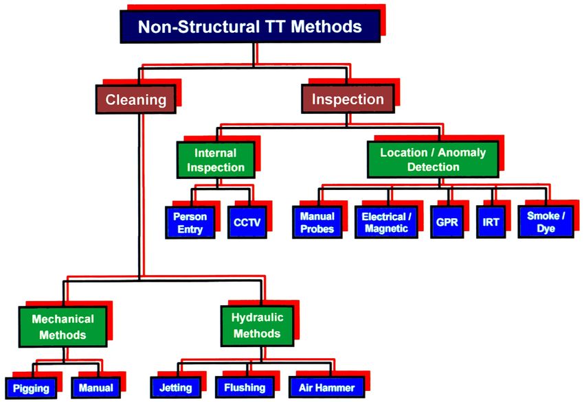
TSPWG Manual 3-260-02.04-4
                                                                                6 June 2019

                                            FOREWORD

This Tri-Service Pavements Working Group Manual supplements guidance found in other
Unified Facilities Criteria, Unified Facilities Guide Specifications, Defense Logistics Agency
Specifications, and Service-specific publications. All construction outside of the United States is
also governed by Status of Forces Agreements (SOFA), Host Nation Funded Construction
Agreements (HNFA), and, in some instances, Bilateral Infrastructure Agreements (BIA).
Therefore, the acquisition team must ensure compliance with the most stringent of the TSPWG
Manual, the SOFA, the HNFA, and the BIA, as applicable. This manual provides general
information and guidance on the use of TT in constructing, reconstructing, rehabilitating,
renovating, cleaning, inspecting, locating, and detecting anomalies around underground
pipelines, utilities, fuel hydrant lines, or communication lines crossing under Air Force
pavements, including runways, taxiways, aprons, overruns, and roadways. The information in
this TSPWG Manual is referenced in technical publications found on the Whole Building Design
Guide. It is not intended to take the place of Service-specific doctrine, technical orders (T.O.),
field manuals, technical manuals, handbooks, Tactics, Techniques, and Procedures (TTP), or
contract specifications, but should be used along with these to help ensure pavements meet
mission requirements.

TSPWG Manuals are living documents and will be periodically reviewed, updated, and made
available to users as part of the Services’ responsibility for providing technical criteria for military
construction, maintenance, repair, or operations. Headquarters, U.S. Army Corps of Engineers
(HQUSACE), Naval Facilities Engineering Command (NAVFAC), and the Air Force Civil
Engineer Center (AFCEC) are responsible for administration of this document. Technical
content of this TSPWG Manual is the responsibility of the Tri-Service Pavements Working
Group (TSPWG). Defense agencies should contact the preparing activity for document
interpretation. Send recommended changes with supporting rationale to the respective Service
TSPWG member.

TSPWG Manuals are effective upon issuance and are distributed only in electronic media from
the following source:

    •   Whole Building Design Guide website: http://dod.wbdg.org/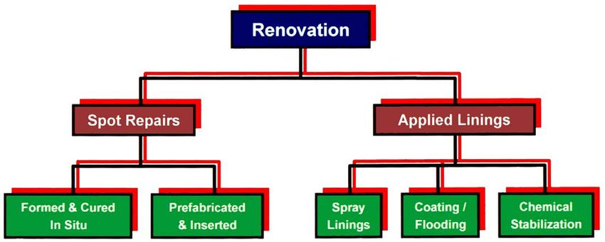
TSPWG Manual 3-260-02.04-4
                                                                         6 June 2019

       TRI-SERVICE PAVEMENTS WORKING GROUP MANUAL (TSPWG M)
                        NEW SUMMARY SHEET

Document: TSPWG Manual 3-260-02.04-4, Trenchless Technology (TT) for Crossing
Pavements

Superseding: Air Force ETL 04-4, Trenchless Technology (TT) for Crossing Air Force
Pavements, dated 31 March 2004

Description: This TSPWG provides general information and guidance on the use of TT
in constructing, reconstructing, rehabilitating, renovating, cleaning, inspecting, locating,
and detecting anomalies around underground pipelines, utilities, fuel hydrant lines, or
communication lines crossing under pavements, including runways, taxiways, aprons,
overruns, and roadways.

Reasons for Document: This TSPWG M provides designers and maintenance
personnel with materials and methods for the use of TT.

Impact: There will be minimal cost impacts that are offset by the overall lifecycle cost.

Unification Issues: There are no unification issues.
TSPWG Manual 3-260-02.04-4
6 June 2019
TABLE OF CONTENTS
CHAPTER 1 INTRODUCTION ...................................................................................... 1
1-1 PURPOSE AND SCOPE. ......................................................................... 1
1-2 APPLICABILITY. ...................................................................................... 1
1-3 GLOSSARY. ............................................................................................. 1
1-4 REFERENCES. ........................................................................................ 2
CHAPTER 2 TRENCHLESS TECHNOLOGY: MATERIALS AND METHODS ............. 3
2-1 HISTORY. ................................................................................................. 3
2-2 CONSIDERATIONS. ................................................................................ 3
2-2.1 System Characteristics. ........................................................................ 3
2-2.2 Site Conditions. ..................................................................................... 3
2-2.3 Constructability. .................................................................................... 3
2-2.4 Cost. ..................................................................................................... 3
2-3 ADVANTAGES. ........................................................................................ 4
2-3.1 Size Range. .......................................................................................... 4
2-3.2 Pipe Types. ........................................................................................... 4
2-3.3 Pipe Shapes. ........................................................................................ 4
2-3.4 Site Preparation. ................................................................................... 4
2-3.5 Dewatering. ........................................................................................... 4
2-3.6 Safety. ................................................................................................... 5
2-3.7 Environmental Impact. .......................................................................... 5
2-3.8 Replacement of Excavated Materials. .................................................. 5
2-3.9 Depth. ................................................................................................... 5
2-3.10 Reduction in Operation and Maintenance (O&M) Costs. ...................... 5
2-4 APPLICABILITY OF SPECIFIC TT METHODS. ...................................... 5
2-4.1 Local Geology. ...................................................................................... 6
2-4.2 Time/Mission Disruption. ....................................................................... 6
2-5 PERFORMANCE SPECIFICATIONS. ...................................................... 7
2-6 TT TYPES. ................................................................................................ 8
2-6.1 New Construction or Reconstruction. ................................................... 8
2-6.2 Renovation. ......................................................................................... 12
2-6.3 Rehabilitation. ..................................................................................... 13
2-6.4 Non-structural Methods. ...................................................................... 16
iTSPWG Manual 3-260-02.04-4
6 June 2019
2-7 INFORMATION SOURCES. ................................................................... 19
2-8 USE OF TT. ............................................................................................ 20
2-9 ADDITIONAL CONSIDERATIONS. ....................................................... 21
APPENDIX A TT METHODS ....................................................................................... 23
APPENDIX B GLOSSARY .......................................................................................... 27
APPENDIX C REFERENCES ...................................................................................... 29
iiTSPWG Manual 3-260-02.04-4
6 June 2019
CHAPTER 1 INTRODUCTION
1-1 PURPOSE AND SCOPE.
This TSPWG M provides general information and guidance on the use of TT in
constructing, reconstructing, rehabilitating, renovating, cleaning, inspecting, locating,
and detecting anomalies around underground pipelines, utilities, fuel hydrant lines, or
communication lines crossing under pavements, including runways, taxiways, aprons,
overruns, and roadways.
1-2 APPLICABILITY.
This TSPWG M is applicable to all DOD installations. Consideration of TT is
encouraged in all instances where a project involves work on an underground pipeline,
utility, fuel hydrant line, or communication line crossing under a runway, taxiway, apron,
overrun, or roadway. When considering the use of TT, seek input/guidance from the
Pavements Discipline Working Group (DWG) or their designated representative and the
appropriate functional engineer for the system involved.
Intended users include the following:
• All pavement engineers, utility system engineers, and fuel system
engineers
• Design engineers and others responsible for constructing, reconstructing,
rehabilitating, and renovating facilities (including, but not limited to,
underground pipelines, utilities, fuel hydrant lines, and communication
lines) or for cleaning, inspecting, locating, and detecting anomalies around
underground pipelines, utilities, fuel hydrant lines, and communication
lines
• Air Force, Army, and Navy offices responsible for constructing,
reconstructing, rehabilitating, and renovating facilities or cleaning,
inspecting, locating, and detecting anomalies around underground
pipelines, utilities, fuel hydrant lines, or communication lines
1-3 GLOSSARY.
Appendix B contains acronyms, abbreviations, and terms.
A glossary of TT terminology from the North American Society for Trenchless
Technology (NASTT) is included in Appendix B. Note that the lack of standardization of
terminology in the TT industry is a significant problem. Identical TT terms vary in
meaning with different manufacturers, contractors, researchers, and even with different
individuals within the same organization.
1TSPWG Manual 3-260-02.04-4
6 June 2019
1-4 REFERENCES.
Appendix C contains a list of references used in this document. The publication date of
the code or standard is not included in this document. Unless otherwise specified, the
most recent edition of the referenced publication applies.
2TSPWG Manual 3-260-02.04-4
6 June 2019
CHAPTER 2 TRENCHLESS TECHNOLOGY: MATERIALS AND METHODS
2-1 HISTORY.
The theory and recorded use of trenchless techniques dates back to early Roman
times. Visit the North American Society for Trenchless Technology (NASTT) Web site at
http://www.glsla.ca/about-us for a historical overview of TT.
2-2 CONSIDERATIONS.
TT is viewed as an alternative construction methodology. Consider system
characteristics, constructability, site conditions, and cost when deciding whether to use
TT. Evaluate each opportunity to utilize TT on a case-by-case basis.
2-2.1 System Characteristics.
While TT is ideal for straight-through runs of pipe, it is less well-suited for projects with
such characteristics as numerous service connections, valves, and bends. Additionally,
although very good control of grade is possible using TT, exercise caution when
considering the use of TT for systems that require very tight grade tolerances, such as
lines for petroleum, oil, and lubricant (POL) products.
2-2.2 Site Conditions.
Consider the in situ site conditions and the presence of underground interferences,
whether natural (e.g., boulders) or man-made (e.g., underground structures and utilities)
when deciding whether to use TT. Compared to soil deposits, the presence of natural
rock or coral deposits can increase drilling costs, while underground interferences can
cause alignment problems (i.e., deflections) during TT operations.
2-2.3 Constructability.
The presence of qualified, experienced, certified contractors and equipment operators is
essential to the success of a TT project, as is the availability of the proper equipment
and materials for the job and site conditions. These factors are more likely to be a
problem at overseas, remote, or hostile environment locations.
2-2.4 Cost.
Since TT is an alternative construction methodology, compare its cost to that of
conventional techniques such as cut-and-cover (i.e., trenching and backfilling) before
deciding to use TT. In the cost analysis, include the indirect costs of conventional
construction techniques, such as the need for a longer construction time or the
disruption caused by having to close a pavement section.
3TSPWG Manual 3-260-02.04-4
6 June 2019
2-3 ADVANTAGES.
The most important advantage of TT is that it minimizes disruption to both aboveground
facilities (e.g., runways, hangars) and belowground facilities (e.g., existing utilities,
bunkers). Other important collateral advantages of TT are:
2-3.1 Size Range.
TT can be used to create almost any size range, from a tiny conduit for a fiber optic
cable to a multilane vehicle tunnel.
2-3.2 Pipe Types.
TT can use virtually any type of pipe, although some pipe types are better suited for
particular TTs. Some pipe types commonly used in TT are:
• Steel pipe
• Polyvinyl chloride (PVC) pipe
• Polyethylene (PE) pipe
• Vitrified clay pipe
• Reinforced concrete pipe
• Polymer concrete pipe
• Fiberglass reinforced pipe
2-3.3 Pipe Shapes.
TT can use a wide variety of pipe shapes. The most commonly used shape is circular
but TT can also use oval, elliptical, and semi-elliptical pipe shapes as well as a variety
of box shapes. In addition, modular and other advanced construction techniques can be
used to create unusual cross-sections.
2-3.4 Site Preparation.
TT can minimize the time needed for site preparation and/or the amount of disturbance.
Common TT techniques require either no digging or digging of a drive pit and a
receiving pit (adjacent to the ends of the pipe segment, on opposite sides). Even when
pits are used, the amount of disturbance is significantly less than for a fully excavated
trench. Not only is the disturbance reduced but it can also be localized to areas that are
not mission-critical (e.g., away from the main runways and taxiways).
2-3.5 Dewatering.
While some systems, like POL lines, need to be protected from contamination from
water, mud, salt, and debris, many projects employing TT techniques will require little or
no dewatering.
4TSPWG Manual 3-260-02.04-4
6 June 2019
2-3.6 Safety.
TT is safer than conventional trench excavation for several reasons:
2-3.6.1 Conventional excavating techniques usually require person-entry within
the trench to lay the pipe. Even when a conventional trench is shallow, without proper
support (e.g., shore jacks, trench “boxes”) there is still a danger of collapse. In addition,
even when reinforcement or other safety equipment is required by contract, many
workers do not take full advantage of the protection because of the sharp decrease in
productivity associated with the use of in-trench safety equipment.
2-3.6.2 In sharp contrast to conventional construction techniques, most TTs do
not require person-entry within the “trench” area. In addition, most TTs only require
person-entry in insertion/receiving pits that are relatively easy to reinforce. Even in
those TTs that require person-entry within the “trench” area (e.g., tunneling), the person
is usually completely enclosed by a supporting pipe with sufficient strength to help
guarantee the person’s safety in case of collapse.
2-3.7 Environmental Impact.
Because TT methods minimize soil disturbance and dewatering, environmental damage
is correspondingly minimized.
2-3.8 Replacement of Excavated Materials.
Open trenches across a pavement almost always require replacement of a significant
portion of the removed material to maintain pavement strength and stability. Since TTs
minimize the disturbance of the in situ materials, the surrounding materials retain their
existing strength and stability without material replacement.
2-3.9 Depth.
There is a practical limit to conventional trenching (i.e., the depth a hoe or digger can
reach) but virtually no limit to the depth for which TT can be used. In cases where
existing underground structures, or even existing underground utilities, create an area of
concern, TT can be used to go far beneath the problem.
2-3.10 Reduction in Operation and Maintenance (O&M) Costs.
TT can reduce O&M costs by returning pipe systems to their design capacity (or
sometimes even better than design capacity), often at a fraction of the cost of
conventional reconstruction.
2-4 APPLICABILITY OF SPECIFIC TT METHODS.
No single TT method is best for all cases and applicability is contingent upon specific
conditions.
5TSPWG Manual 3-260-02.04-4
6 June 2019
2-4.1 Local Geology.
Local geology/subsurface conditions usually preclude the use of one single TT for all
cases. This statement is supported by the Transportation Research Board (TRB),
National Cooperative Highway Research Program (NCHRP) Synthesis 242, Trenchless
Installation of Conduits Beneath Roadways, which addresses roadway utility crossings.
The TRB compiled results of survey responses on TT from the departments of
transportation (DOT) in 33 American states and six Canadian provinces. The TRB study
had one major conclusion:
No one method is suitable for all types of utilities or all types of soil or site
conditions. The selection of compatible methods is site specific and highly
dependent on subsurface conditions. Therefore, an adequate soils
investigation and an accurate underground utility location program are
critical for minimizing subsequent construction problems and claims.
2-4.2 Time/Mission Disruption.
Since mission capability is often the controlling factor in pavement crossings, there are
several other factors related to time or mission disruption that preclude the use of one
single TT for all cases.
2-4.2.1 Equipment Availability.
Equipment availability is a key issue in the use of TT for pavement crossings. Unlike
DOTs (with local jurisdiction), DOD has a worldwide jurisdiction and with force
projection comes the possibility of pavement crossing problems anywhere on the globe.
Depending on the TT chosen, local equipment may not be available or adaptable to
solve a particular problem.
2-4.2.2 Materials Availability.
Local materials availability may affect the choice of TT for a particular problem or
location. In this context, “materials” refers to items such as the pipe, pipe liner, grout,
and drilling mud. The exact definition of “materials” will vary with the choice of TT
method.
2-4.2.3 Adjacent Area Availability.
The availability and usability of adjacent areas may determine the choice of TT. For a
technology that requires an insertion pit or a receiving pit, ensure there is an adjacent
area that can be excavated. Other TTs that do not require a pit (e.g., horizontal
directional drilling [HDD]) still require a significant staging area but the staging area
does not always have to be adjacent to the pavement.
2-4.2.4 Specialized Training.
The need for specialized training may restrict or eliminate the choice of some TTs for a
particular need in a particular area (e.g., in a dangerous area). The engineer who
6TSPWG Manual 3-260-02.04-4
6 June 2019
considers the choice of a TT must also consider that the same personnel who can
perform a wide range of other construction activities may not be capable of operating,
for example, a computer-controlled directional drilling machine. The issue of training
may not be as critical for peacetime construction performed by a qualified civilian
contractor but it could be a controlling issue in a force-projection environment. In any
event, ensure a TT contractor for a pavement crossing has adequate training and
experience to ensure a safe and satisfactory result and any TT equipment operator has
been properly and specifically trained on the TT equipment that will be used by that
operator.
2-4.2.5 Use of Sleeves.
For any pressurized utility or fuel line crossing under an active pavement (runway,
taxiway, apron, overrun, or roadway), a TT which includes the use of a protective sleeve
is highly recommended when extreme loadings may cause undue stresses on the
pipeline. (Note: Such situations can usually be mitigated through the use of an
increased pipe wall thickness and/or a greater depth of pipeline cover.) When a sleeve
is used, the sleeve material should be of a type and strength that will minimize the risk
of external leakage in the event of a breach in the main pipeline since external leakage
could cause environmental contamination, structural weakening of the pavement
support system, or other danger (e.g., fire). In addition, ensure the sleeve system has
adequate venting to maintain integrity and safety at all times, specifically in the case of
a breach in the main pipeline. Specific design and performance criteria (e.g., the need
for protective coatings and cathodic protection) and venting requirements for the
sleeves will depend on the TT chosen, the type of pressurized pipeline, and the material
to be transported within the pressurized pipeline. When a sleeve is used for a
cathodically protected pipeline: (1) center the carrier pipe in the sleeve using non-
metallic devices and (2) fill the annular space with clean, non-corrosive fill material to
allow cathodic protection current to reach the entire surface of the carrier pipe. Consult
a corrosion control specialist certified by the National Association of Corrosion
Engineers (NACE) when designing such work.
2-5 PERFORMANCE SPECIFICATIONS.
A growing number of DOTs are using performance specifications rather than product
specifications for most, if not all, of their TT contracts for roadway crossings. With the
growing number of methods and materials available, it is becoming harder and harder to
write a good product specification that will allow contractors to use the best TT for a
particular job (i.e., one that will maximize benefits and minimize cost), whereas
performance specifications place the responsibility on the contractor to deliver a finished
product with adequate performance characteristics to satisfy mission needs. For
mission-critical systems like POL lines, the use of product specifications may still be
preferable.
7TSPWG Manual 3-260-02.04-4
6 June 2019
2-6 TT TYPES.
Appendix A illustrates the major types of TT currently available. Hybrids of the major
methods create a plethora of choices for a given TT application; however, the various
methods can be separated into four major groups, three of which can be considered
structural (new construction or reconstruction, renovation, and rehabilitation) and two
non-structural (cleaning and inspection, including pipeline location and anomaly
detection).
2-6.1 New Construction or Reconstruction.
Construction methods may be categorized as either surface-launched or non-surface-
launched.
2-6.1.1 Surface-launched.
In general, surface-launched TTs start by drilling a pilot hole that is then expanded by
“backreaming” (i.e., pulling an enlarging cutting head back through the pilot hole) before
pulling in the pipe. Backreaming can be done separately from, or in conjunction with,
pipe pullback. An alternate method uses the pilot hole as a guide, with a cutting head
and pipe being pushed along the guide path (similar to microtunneling). The main
surface-launched TTs are HDD and guided boring; a hybrid type, the midi rig, is often
referred to as a third type.
2-6.1.1.1 Guided Boring.
In the TT industry, the term “guided boring” is sometimes used generically to mean any
horizontal boring with any degree of control over the drill head; however, the term is
more commonly used to describe a type of small-scale, surface-launched boring rig that
has a limited capability for guiding the auger head. Guided borings are often used by
utility companies for highway crossings and are particularly cost-effective when several
crossings need to be made in a single geographical area. The major advantage over
traditional (horizontally oriented) rotary drilling methods is that no drive pit or receiving
pit is needed. The major disadvantage is the mobilization cost of the specialized
equipment and operators, which is why this method is often used only for multiple
crossings.
2-6.1.1.2 Horizontal Directional Drilling (HDD).
HDD is essentially a larger-scale, higher-technology version of guided boring, usually
with computerized remote control over the drilling head. (In fact, some vendors refer to
a guided boring rig as a “mini HDD.”) In sharp contrast to guided boring rigs, the largest
HDDs are capable of traveling several miles underground with remotely controlled
guidance (using radio-driven locator technology to track the drilling head). The major
advantage of HDD is the relatively large depths and relatively long distances that can be
traversed. HDD has been used for crossings under rivers, lakes, multi-lane highways,
and airports. Mobilization costs remain the major disadvantage of this method, even
more so than for guided boring.
8TSPWG Manual 3-260-02.04-4
6 June 2019
2-6.1.1.3 Midi Rig.
Many vendors consider midi rig boring, a hybrid TT technique, a separate surface-
launched method. The size of a midi rig varies but it falls somewhere between a guided
boring rig and an HDD rig. Similarly variable, the remote location and guidance
capabilities of a midi rig would usually be thought of as better than a guided boring rig
but not as effective as an HDD rig; it is essentially a “supercharged” guided boring rig or
“scaled-back” HDD rig. The advantages and disadvantages of a midi rig are similar to
those of guided boring (paragraph 2-6.1.1.1) and HDD (paragraph 2-6.1.1.2).
2-6.1.2 Non-Surface-Launched.
These methods may be divided into several types: boring/coring, push/pull (includes
pipe jacking, pipe pullback, and pipe pulling), compaction, pipe ramming, water
pressure, tunneling, and microtunneling. In TT terms, tunneling and microtunneling are
considered “stand-alone” technologies; the other methods are used in conjunction with
other TT methods to produce installed pipelines.
2-6.1.2.1 Boring/Coring.
Boring/coring refers to traditional auger boring/coring rigs mounted horizontally. In TT
terms, this is distinguished from guided boring or HDD by a lack of directional control at
the cutting head. In traditional boring/coring, a receiving pit is used to “catch” the drilling
apparatus so localized directional control is not required.
2-6.1.2.2 Push/Pull.
Push/pull methods such as pipe jacking, pipe pullback, and pipe pulling use hydraulic,
mechanical, or air jacks to push or pull a pipe through a horizontal stratum.
2-6.1.2.2.1 “Pipe jacking” is a term that has various meanings and usages within the
TT industry and is sometimes even used to refer to any TT method. Though this
TSPWG M explains and categorizes pipe jacking methods, be aware that the term “pipe
jacking” can have widely differing meanings depending on the source (see paragraphs
2-6.1.2.3 and 2-6.1.2.4). The most common use of the term “pipe jacking,” however, is
to describe any of several methods that use jacks to push or pull an open pipe through
a horizontal stratum, with spoil removal either before or after inserting the pipe.
2-6.1.2.2.2 Pipe pullback is usually distinguished from pipe jacking by the location of
the jack relative to the pipe insertion; that is, when the jack is located behind the pipe
insertion so the jack puts the pipe in compression, the method is usually referred to as
pipe jacking. When the pipe is pulled back through a previously drilled borehole so the
pipe is put in tension, the method is usually referred to as pipe pullback. In the case of a
pipe being pulled directly behind the cutting heads using a cable through a previously
bored guide hole, there is no clear consensus on which term (i.e., pipe jacking or pipe
pullback) should be used, even though the pipe is clearly being put in tension.
2-6.1.2.2.3 Usually pipe jacking is the method preferred in collapsible strata, whereas
pipe pullback is preferred in self-supporting strata, although the preference may also
9TSPWG Manual 3-260-02.04-4
6 June 2019
depend on equipment availability. Either technique may be used in boreholes stabilized
with fluid (e.g., driller’s mud).
2-6.1.2.2.4 Pipe jacking is not limited to circular or elliptical cross-sections. Box-
shaped cross-sections may be used in soft strata or even in stiff strata if oversize cutting
heads are used ahead of the jacked pipe. Modular jacking has been used to build up
support for structural components (such as bridge abutments) out of modular units
jacked into soft soil. In addition, pipe jacking may be used to create an advanced
support structure (ASS). The ASS is an enclosing support environment created by a
series of closely spaced jacked pipes that form walls and/or ceilings, or often an
archway, before excavation inside or underneath the ASS. In some cases, grout or glue
is injected to fill the spaces between pipes; in other cases, the pipes are reinforced
during or after excavation; and in some cases, particularly for temporary use, the ASS is
used without interior reinforcement.
2-6.1.2.2.5 Though pipe pulling is a traditional utility industry TT technique, the term
“pipe pulling” is frequently misused as a synonym for pipe pullback. In pipe pulling, an
existing pipe is removed simultaneously with new pipe installation by a single pulling
action. Because of side friction, this method is usually limited to very-small-diameter
pipes with relatively short runs. While this technique is often overlooked in TT
discussions (it is “low-tech” and has limited application), it is probably the best TT
method in cases where its use is viable.
2-6.1.2.3 Compaction.
Compaction methods are usually distinguished from jacking methods because they do
not remove spoil (the term “pipe jacking” is sometimes used generically to describe
these methods as well); that is, the soil around the pipe is compacted in situ and
remains around the installed pipe. When a closed pipe is driven, compaction is
generically called “piercing.” When a mechanical or hydraulic jacking system is used,
piercing is often referred to as the push rod method; when a percussive system is used
to drive the pipe, piercing is often referred to as impact moling; and when a horizontally
mounted pile driver is used to drive the pipe, piercing is usually referred to as pipe
ramming (paragraph 2-6.1.2.4). The use of auger-like cutting heads that both dislodge
and compact the soil is often referred to as the rotary method or “cutting.”
2-6.1.2.4 Pipe Ramming.
The term “pipe ramming” is often generically used for any insertion of a pipe using a
percussive device, particularly if the device is a horizontally mounted pile driver;
therefore, the term “pipe ramming” is sometimes used in place of “pipe jacking” (i.e.,
spoil removed) but also sometimes used in place of “piercing” (i.e., spoil compacted in
place).
10TSPWG Manual 3-260-02.04-4
6 June 2019
2-6.1.2.5 Water Pressure.
2-6.1.2.5.1 Fluid-assisted Boring.
Fluid-assisted boring uses a combination of mechanical drilling and pressurized fluid
jets to provide the cutting action. This method is commonly used in rock coring or boring
through extremely stiff soils.
2-6.1.2.5.2 Jet Cutting.
Jet cutting (sometimes referred to as “jetting”) is a specialized piercing method,
particularly useful in sandy soils, in which a water jet is used to “liquefy” the soil in
advance of the inserted pipe (i.e., it makes the sand “quick”). As with pipe pulling, this
method is limited to relatively small-diameter pipes with relatively short runs because
side friction acts on that part of the pipe that is not in the vicinity of the jet head. Use of
the term “jetting” as a synonym for jet cutting can lead to confusion because the term
“jetting” is also used to describe a pipe-cleaning method (paragraph 2-6.4.1.1.3).
2-6.1.2.5.3 Slurry Shield.
The slurry shield method uses a mechanical tunneling shield with a closed face and
uses a liquid (usually water) to remove the excavated material and balance the ground
water pressure. In another confusion of terminology, however, “slurry boring” is also
used generically to describe any auger boring with driller’s mud; that is, “slurry boring”
and “auger boring,” respectively, are sometimes used to distinguish “wet” drilling from
“dry” drilling.
2-6.1.2.6 Tunneling.
Tunneling methods include any technique that involves excavating soil or rock at the
leading edge of a shield or boring machine and erecting a lining system from within the
excavated space. Traditional tunneling methods range from removal by hand to
sophisticated excavators. Hand-bolted segmental rings are frequently used in traditional
tunneling, although shotcrete/gunite (i.e., blown concrete) is gaining in popularity for
larger tunnels because of increased productivity (i.e., faster advance rates). The
modern tunneling method uses a tunnel boring machine (TBM). TBMs are currently
used worldwide to create large tunnels (e.g., for subways or highway tunnels). The
distinguishing feature of all tunneling methods is that they allow person-entry during
excavation and lining.
2-6.1.2.7 Microtunneling.
Microtunneling installs pipe using a microtunnel boring machine (MTBM). The term
“microtunneling” refers to the fact that person-entry is not required (in fact, it is usually
not possible) during tunneling. The term “microtunneling” is frequently misunderstood
and misused because it refers to the remote-control aspect of the method (i.e., no
person-entry needed), not the size of the tunnel. In fact, microtunnels can be quite
large. MTBMs typically use pipe jacking to insert pipe just behind the cutting head (the
11TSPWG Manual 3-260-02.04-4
6 June 2019
jacked pipe continuously supports the tunneling operation) but in self-supporting strata
(especially rock), pipe pullback is an alternative (paragraph 2-6.1.2.2.2).
2-6.2 Renovation.
In this TSPWG M, renovation is defined as a repair technique that depends, in part, on
the original pipe for support after the upgrade is completed. That definition was adopted
for this TSPWG M for two reasons: (1) that definition is commonly used in the TT
industry and (2) that definition is convenient for grouping TT methods. Note, however,
that it is also common within the TT industry to use the terms “renovation” and
“rehabilitation” interchangeably. Renovation, as defined in this TSPWG M, is most often
used in pipes large enough for person-entry. The two main types of renovation are spot
repairs and applied linings. For POL lines, repair and liner materials must be capable of
withstanding exposure to both the product and any additives, and should be approved
by the service control point for all Defense Logistics Agency (DLA) fuel-related support
issues, such as the Air Force Petroleum Office (AFPET).
2-6.2.1 Spot Repairs.
Spot repairs are usually both formed and cured in situ or prefabricated and inserted.
2-6.2.1.1 Traditionally, formed and cured in situ spot repairs were limited to
manually formed repairs on large concrete storm sewers. More recently, however, the
term “formed and cured in situ repairs” refers to a number of techniques that involve the
use of a “packer” (sometimes called a “balloon”), which is cylindrical in shape, pulled
into the area to be repaired and then inflated, sometimes bridging a damaged joint. The
packer is then used as a form to hold a polymer concrete or other specialized grouting
material that is injected through the packer and into the damaged pipe (and sometimes
into the surrounding fill material).
2-6.2.1.2 In TT terms, “prefabricated and inserted repairs” refers to a number of
methods in which pipe segments are grouted or glued in place. Although most
prefabricated and inserted repairs are done by person-entry, there are two exceptions:
cured-in-place repairs and sophisticated robotic repairs.
2-6.2.1.2.1 Cured-in-place Repairs.
Cured-in-place repairs are patches that are inserted in a reduced or deformed (i.e.,
folded) shape, expanded by one of several different methods to fit the inside of the pipe
in the distressed area then held in place until cured.
2-6.2.1.2.2 Sophisticated Robotic Repairs.
Although most cured-in-place repairs use some robotic components to complete the
repairs, the term “sophisticated robotic repairs” refers to a highly specialized area of TT
that is most commonly used in the nuclear industry and has prohibitively high costs. The
description of sophisticated robotic repairs is beyond the scope of this TSPWG M, but it
is important to note that the term “robotic repair” is sometimes used generically in the
12TSPWG Manual 3-260-02.04-4
6 June 2019
TT industry to describe any repair done by remote control, especially if a closed-circuit
television (CCTV) camera is used.
2-6.2.2 Applied Linings.
Grouts, glues, polymers, or other exotic materials applied by spray or flooding are
considered applied linings. Due to the traditional need for surface preparation, most
applied lining renovations are in large pipes with person-entry; however, recent
advances in chemical (polymer) grouts have reduced the requirements for surface
preparation and recent equipment advances have improved the ability to deliver the
lining material into smaller pipes. Chemical stabilization is a renovation method used to
simultaneously repair a pipe defect and stabilize the surrounding soil; that is, the
polymer flows out through the pipe defect into the surrounding soil and, when the
polymer sets, it both stabilizes the soil and patches the pipe defect. Even with these
advances, however, small pipe applied linings are usually not cost-competitive when
compared with other TT methods, particularly in terms of the life-cycle cost. The
exception may be in potable water lines, particularly metal pipes, where the combination
of pigging (paragraph 2-6.4.1.2.1) and spray lining can be a cost-effective way to
remove tuberculations (chemical deposits usually associated with “red water”) and
return the pipe to a nearly new condition. Both cement mortar and polymer lining
systems are currently available for renovating potable water lines.
2-6.3 Rehabilitation.
In this TSPWG, “rehabilitation” is defined as a repair technique that does not depend on
the original pipe for support after the upgrade is completed. This definition was adopted
here because it is commonly used in the TT industry and is convenient for grouping TT
methods. As noted in paragraph 2-6.2, however, it is also common within the TT
industry to use the terms “renovation” and “rehabilitation” interchangeably. As defined in
this TSPWG M, rehabilitation methods can be further divided into three groups: applied
lining methods, prefabricated lining methods, and upsizing. Both of the lining methods
have the disadvantage of causing a reduction in pipe capacity (in addition to the
disadvantage of usually needing person-entry). Upsizing, as its name implies, can
return the pipe to its original capacity, or even increase its capacity, without person-
entry. Still, there are many cases where a pipeline requires less than its original
capacity (e.g., if a conventional communications cable was being replaced with a fiber
optic cable) and, in those cases, lining methods remain a useful rehabilitation
alternative. For POL lines, ensure liner materials are capable of withstanding exposure
to both the product and any additives, and should be approved by the service control
point for all DLA fuel-related support issues, such as AFPET.
2-6.3.1 Applied Lining.
Applied linings for rehabilitation are usually restricted to large pipes, with installation
techniques similar to those for renovation linings (paragraph 2-6.2.2), but usually with
thicker application and/or stronger material. Gunite/shotcrete (i.e., blown concrete) is
gaining in popularity for large-pipe rehabilitation, particularly using advanced concrete
mixes such as fiber-reinforced concrete.
13TSPWG Manual 3-260-02.04-4
6 June 2019
2-6.3.2 Prefabricated Lining.
There are four main rehabilitation methods using prefabricated linings: insert renewal,
modified sliplining, spiral wound lining, and segmented lining. All four techniques are
sometimes referred to generically as sliplining but the term sliplining is properly applied
only to insert renewal and modified sliplining.
2-6.3.2.1 Insert Renewal.
Insert renewal is the simplest and most commonly used type of sliplining, particularly in
pipes with no internal tees. As its name implies, a finished pipe is inserted inside the
original pipe. While the simplest of the sliplining methods both in concept and in
execution, it is often not the ideal solution because it typically is also the method that
most reduces pipe capacity.
2-6.3.2.2 Modified Sliplining.
Modified sliplining involves slipping a lining with a reduced diameter inside the existing
pipe and then expanding the lining. Modified sliplining is usually separated into cured-in-
place pipe (CIPP) and fold and form pipe, although both of these methods involve
curing the lining in place.
2-6.3.2.2.1 CIPP.
CIPP is installed as a flexible insert (sometimes referred to as a “sock”) then expanded
and cured. CIPP is typically resin-impregnated but other exotic materials are also used.
Many CIPP installation procedures require that the insert be subsequently pulled inside-
out. CIPP has recently become a more popular rehabilitation technique but price
remains a concern because of the expense of the materials required to produce the
blend of thinness, flexibility at insert, and strength after curing. Other benefits, however,
such as less installation time or less disruption of mission capability, may offset the
higher material costs of CIPP.
2-6.3.2.2.2 Fold and Form Pipe.
Also known as deformed and reformed pipe, fold and form pipe is usually distinguished
from CIPP although they are closely related. The most common type of fold and form
pipe is folded at roughly the midline of the liner so the insert forms a “U” shape. (In
some products, the “U” shape is folded again so the liner is flat for insertion.) The folded
pipe is either pushed or pulled through the original pipe and then inflated/expanded and
cured in place. Fold and form pipe is easier to insert and cure in specific sections of
pipe than other modified sliplinings and therefore lends itself better for rehabilitation of
pipes with internal tee joints (that is, it can be used as a very long spot repair between
the tees). Unfortunately, like other types of modified sliplining, fold and form inserts tend
to be expensive. As with CIPP, however, other factors (e.g., less installation time or less
disruption of mission capability) may offset the higher material costs.
14TSPWG Manual 3-260-02.04-4
6 June 2019
2-6.3.2.3 Spiral-wound Lining.
This technique uses a ribbed plastic strip that is spirally wound by a winding machine to
form a liner. The liner is sometimes grouted and sometimes expanded and cured in
place. In large-diameter pipes, the strips are sometimes formed into panels and
installed by hand (which would probably be more properly categorized as a segmented
lining but usually is not).
2-6.3.2.4 Segmented Lining.
The term “segmented lining” is used to describe either the use of short pieces of flexible
(or folded) pipe insert (similar to spot repair liners) installed as overlapping panels that
are either grouted or glued in place to form a continuous pipe liner or the use of
segments of pipe that are butted and either grouted or glued in place to form a
continuous pipe liner. Typically, these methods are used only in large-diameter pipes
that allow person-entry. Segmented linings are becoming less favored because they
have the disadvantages of spot repairs but none of the installation advantages of
seamless lining systems.
2-6.3.3 Upsizing.
Upsizing can be further subdivided into two types: pipe eating and pipe bursting. These
two methods are conceptually similar in that both put a pipe of the same or larger size
back in the position where the defective pipe was located and both cause minimal
disturbance of surface assets but the mechanics of the methods are dissimilar: Pipe
eating is a tunneling technique (with spoil removal) and pipe bursting is a compaction
technique.
2-6.3.3.1 Pipe Eating.
Although MTBMs are used most often in new construction, they can also be used in a
rehabilitation technique known as pipe eating, in which the MTBM is run along the axis
of a defective pipe to remove the defective pipe with the near-surrounding soil (while the
replacement pipe is inserted). While technically this method would qualify as a
reconstruction technique, the TT industry typically refers to pipe eating as a
rehabilitation technique (a logical designation for practical purposes [i.e., for bidding]
even though it is technically incorrect). Before being “eaten,” the defective pipe is
sometimes pre-filled with grout, which can improve the performance of the MTBM but
increases the need for crushing capability during the “eating” process (this variation of
pipe eating is sometimes referred to as pipe crushing). In addition, some pipe-eating
systems employ a proboscis-like device to seal the pipe in front of the MTBM shield to
collect and divert existing flow, thus allowing a sanitary sewer, for example, to remain
"live" during the rehabilitation process.
2-6.3.3.2 Pipe Bursting.
Pipe bursting is rapidly becoming the method of choice for pipe rehabilitation,
particularly in spans of pipe that have no internal tee joints. In this technique, a splitting
tool (typically called a “bullet”) is pulled by cable through the original pipe, along with a
15TSPWG Manual 3-260-02.04-4
6 June 2019
replacement pipe. The bullet may simply rely on its geometry to transfer the cable force
to the pipe for splitting but more sophisticated bullets are mechanized to actually
expand outward to create splitting tensile forces (usually used only as needed). The
principal advantage of pipe bursting over sliplining techniques is that pipes as large as
or larger than the original pipe can be inserted. This means the pipe can be returned to
its original capacity or more and exotic replacement pipe materials are not required. An
additional advantage of pipe bursting over most other rehabilitation techniques is that no
surface preparation or even pipe cleaning is needed (although constrictions/blockages
of sufficient size and strength to “stop the bullet” have to be addressed prior to
beginning bursting). Pipe bursting usually has a minimal effect on surface assets since
the amount of material being compacted is usually small compared to the original pipe’s
cross-section. Even so, pipe bursting is a compaction method, and the amount of
surface disturbance depends to some extent on the quantity and quality of the original
backfill material, the depth of burial, and the surrounding soil conditions, and depends to
a great extent on the increase in size of the upsized pipe compared to the original pipe.
2-6.4 Non-structural Methods.
Non-structural TT methods are often overlooked in technical discussions of TT methods
even though they are the most common use of TT. Non-structural TT methods can be
divided into two groups: cleaning and inspection (including pipeline location and
anomaly detection).
2-6.4.1 Pipe Cleaning.
Although there are many variations and combinations of the individual cleaning
techniques, all commonly used pipe-cleaning methods can be grouped as either
hydraulic or mechanical.
2-6.4.1.1 Hydraulic Cleaning.
There are two types of hydraulic cleaning: flushing and jetting; however, a variant of
flushing called the “air hammer method” is often classified separately. Hydraulic
cleaning is not suitable for POL lines, where contamination of the fuel by residual water
is a possibility and where lines must be vapor-free to prevent the possibility of fire or
explosion before pressurized air is introduced.
2-6.4.1.1.1 Flushing.
Flushing uses a relatively large volume of water flowing through the pipe to induce
cleaning. A fire hydrant is commonly used as the water source for this method since it
provides an adequate volume of water with an adjustable flow rate. Ironically, flushing is
the most common form of pipe cleaning but often the least effective. While loose debris
is almost always flushed from the pipe (giving the appearance the pipe has been
cleaned), more firmly held debris, sediments, chemical deposits, and other materials
that have become embedded or affixed to the pipe walls are typically not removed by
flushing. Still, the method is easy, requires no special equipment or training, and
provides a tangible benefit in most cases.
16TSPWG Manual 3-260-02.04-4
6 June 2019
2-6.4.1.1.2 Air Hammer.
The air hammer method is a variant of flushing. The term “air hammer” is a misnomer,
however, because the method uses an injected air bubble to create a “water hammer”
that increases the cleansing ability of the flushing water. (Most people are familiar with
the water hammer effect because of the loud noise and vibration in faucets and toilets
after the water has been turned off and later turned back on and air is in the water
lines.) The cleansing effect is increased because the water hammer (directly behind the
air bubble) moves with great turbulence. This effect is similar to a massaging
showerhead that sends out intermittent jets of water.
2-6.4.1.1.3 Jetting.
The term “jetting,” when associated with pipe cleaning, refers to any method that
delivers pressurized water to a tip, or head, for thorough cleaning. Jetting requires more
equipment than flushing since the jet head is pulled through the pipe. Jetting can
provide greatly improved cleaning compared to flushing, particularly when used in
conjunction with CCTV inspection, but still cannot always break the mechanical bonds
for complete removal of all deposits.
2-6.4.1.2 Mechanical Cleaning.
There are two types of mechanical cleaning: pigging and manual cleaning.
2-6.4.1.2.1 Pigging.
Pigging is the pulling of a slug, or “pig,” through the pipe for cleaning. The advantage of
pigging is that it can break the mechanical bonds of deposits in smaller pipes that other
cleaning methods cannot. In addition, pigging can be used in conjunction with any of the
other methods for improved cleansing. There are a wide variety of pigs, with varying
sophistication. At the low-technology end, the pig may be a rubber, plastic, or metal
slug. At the high-technology end, the pig may be a mechanical scrubbing machine. In
between, there are many different pigs with various types of abrasive surfaces, studs, or
brushes. For small pipes with severe clogging, pigging may be the only alternative to
reconstruction.
2-6.4.1.2.2 Manual Cleaning.
Large pipes may be manually cleaned. A wide range of techniques fall within this
category, principally limited only by the available equipment and the diameter of the
pipe. All variants on manual cleaning have the same two disadvantages, however:
person-entry is required and small pipes cannot be cleaned by this method.
2-6.4.2 Inspection.
Inspection methods can be divided into two groups: internal inspection and
location/anomaly detection. See TSPWG M, 3-260-03.04-6, Inspection of Pavement
Drainage Systems, for a more detailed study.
17TSPWG Manual 3-260-02.04-4
6 June 2019
2-6.4.2.1 Internal.
Internal pipe inspection is usually done by one of two methods. If the pipe is large, the
inspection is done by person-entry; if the pipe is small, the inspection is done by CCTV.
2-6.4.2.1.1 Person-entry.
The main advantage of a person-entry inspection is that it incorporates the oldest and
most reliable method of inspection: the human eye. During a person-entry inspection,
the inspector can get first-hand information about internal pipe conditions that are
impossible to obtain by any other method. In addition, videotape records or
photographs, guided directly by the inspector, can be used to supplement and
document the inspector’s findings. Measurements and samples can be taken directly. In
every way, when practicable, person-entry is the best method of inspection; however,
safety considerations require that a pipe be of an appropriate size and condition before
person-entry is allowed. See Occupational Safety and Health Administration (OSHA)
rules on confined space entry in Title 29, CFR, Chapter XVII, Section 1910.146, Permit-
required confined spaces.
2-6.4.2.1.2 CCTV.
CCTV is the only proven technology for internal inspection of small pipes. A key factor
for the success of a CCTV inspection is establishing proper reference points so the
video can be tied to exact locations in the pipe being inspected. The biggest
disadvantage of CCTV is the quality of the data is highly dependent on the operator’s
experience and skill. In addition, and particularly when videotape is used for analysis,
the results are highly dependent on the quality of the equipment, its degree of
maintenance, and the timeliness of hardware and software updates. There is a wide
range of equipment for CCTV inspections, usually grouped by the size of pipe to be
inspected. In addition to inspecting the internal condition of the pipe, CCTV can be used
to estimate the infiltration/inflow of water due to leaks in the pipe.
2-6.4.2.2 Location/Anomaly Detection.
While some aspects of location/anomaly detection can be satisfied during an inspection,
this paragraph describes methods used apart from an inspection to simply locate the
pipe or locate specific anomalies in the general area of the pipe. These methods are
grouped as manual probes; electromagnetic locators; ground-penetrating radar (GPR);
infrared thermography (IRT); and smoke/dye.
2-6.4.2.2.1 Manual Probe.
The simplest and most direct method of locating a pipe or large anomaly (such as a
large void) is with a small diameter probe, though manual probes are usually useful only
for pipes/anomalies close to the surface and only for soil surfaces. Since pipes under
pavements are the major concern for TT use, the use of a manual probe will usually be
impossible.
18TSPWG Manual 3-260-02.04-4
6 June 2019
2-6.4.2.2.2 Electromagnetic Locators.
Several different types of locator systems use electrical or magnetic signatures to find a
buried pipe. These methods are most effective when there is metal in the pipe system
(i.e., metal pipe, pipe reinforced with metal rebar, metallic cables within pipe). With the
increased use of plastic pipe and fiber-optic cables, electromagnetic location methods
are becoming less reliable.
2-6.4.2.2.3 Ground-penetrating Radar (GPR).
GPR is particularly well suited for finding large voids (for example, those caused by a
washout in the vicinity of the pipe). GPR can also locate pipes, particularly large pipes.
GPR can quickly provide information about underground structures that no other
nondestructive test can. GPR is not used routinely in inspections because of cost but
since the biggest cost in most GPR surveys is mobilization, a large test area can usually
be surveyed for not much more than the cost of a small test area. Another disadvantage
of GPR is that an experienced operator is needed on-site to interpret the data. The
quality of the results of a GPR survey is highly dependent on the skill of the
operator/data interpreter.
2-6.4.2.2.4 Infrared Thermography (IRT).
IRT has been used with varying degrees of success to locate pipes and voids around
pipes. An IRT scanner measures temperature differences in the surface above the pipe,
which may be significantly influenced by the pipe or by void areas. IRT scanners may
be mounted on a permanent structure but are commonly used on portable overhead
equipment (e.g., cherry picker) or even mounted on aircraft. The main advantage of IRT
is the ability to survey relatively large areas in a short time; however, IRT is usually
effective only for relatively shallow pipelines. Also, since the thermographs are two-
dimensional, the depth of a pipe or void cannot be determined by IRT alone.
2-6.4.2.2.5 Smoke/Dye.
Smoke and dye tests can be used in various configurations and combinations to locate
leaks and sometimes estimate their extent. In addition, these tests are sometimes used
to determine if a pipe is either completely clogged or broken and offset. Conversely,
these tests are sometimes used to verify that a feature is, in fact, connected to a
pipeline (for example, to see if a drop basin is connected to a storm sewer pipe) or to
determine if there is a cross-connection between pipes from different systems. These
tests are conceptually simple although sometimes cumbersome to perform. Smoke/dye
is pumped/injected into the pipe and its appearance (or lack of appearance) is
interpreted.
2-7 INFORMATION SOURCES.
TT is rapidly being accepted worldwide and there are technical societies worldwide that
are available as resources. See Appendix C for a listing of TT societies. There are also
ASTM standards related to trenchless technology; see Appendix C.
19You can also read