Mechanics-Aware Deformation of Yarn Pattern Geometry
←
→
Page content transcription
If your browser does not render page correctly, please read the page content below
Mechanics-Aware Deformation of Yarn Pattern Geometry
GEORG SPERL, IST Austria, Austria
RAHUL NARAIN, Indian Institute of Technology, India
CHRIS WOJTAN, IST Austria, Austria
Fig. 1. Our method uses an underlying cloth mesh (bottom) to animate yarn-level cloth (top) in real-time by approximating the yarn-level response in a
data-driven fashion based on the deformation of the mesh. It reproduces the stretching behavior of knits (left), animates large garments with millions of yarn
vertices (middle), and combines with real-time cloth simulation for end-to-end interactive animation of yarn-level cloth (right). We render the sweater (middle)
using pathtracing and with hair particles.
Triangle mesh-based simulations are able to produce satisfying animations of
knitted and woven cloth; however, they lack the rich geometric detail of yarn-
level simulations. Naive texturing approaches do not consider yarn-level
physics, while full yarn-level simulations may become prohibitively expen-
sive for large garments. We propose a method to animate yarn-level cloth
geometry on top of an underlying deforming mesh in a mechanics-aware
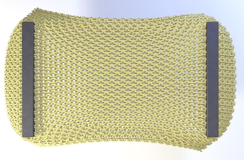
Fig. 2. Deforming a yarn pattern (left) with embedded deformation causes
fashion. Using triangle strains to interpolate precomputed yarn geometry,
it to stretch uniformly (center), which ignores yarn-level physics that should
we are able to reproduce effects such as knit loops tightening under stretch-
make the yarn loops tighten (right).
ing. In combination with precomputed mesh animation or real-time mesh
simulation, our method is able to animate yarn-level cloth in real-time at
large scales.
CCS Concepts: • Computing methodologies → Physical simulation. curl depending on the yarn pattern [Cirio et al. 2016; Sperl et al.
Additional Key Words and Phrases: mechanics-aware, yarn-level cloth, real- 2020].
time, knitted, woven, cloth simulation Existing research focuses either on the level of individual yarns,
or on overall cloth behavior. Direct simulation of individual yarns
ACM Reference Format:
Georg Sperl, Rahul Narain, and Chris Wojtan. 2021. Mechanics-Aware De- [Bergou et al. 2010; Cirio et al. 2016; Kaldor et al. 2008; Sánchez-
formation of Yarn Pattern Geometry. ACM Trans. Graph. 40, 4, Article 168 Banderas et al. 2020] produces detailed yarn behaviors, which can
(August 2021), 11 pages. https://doi.org/10.1145/3450626.3459816 be scaled up to accurately simulate large-scale cloth behaviors albeit
at great computational expense. On the other hand, spring- or mesh-
1 INTRODUCTION based cloth simulation [Baraff and Witkin 1998; Müller et al. 2007;
The intricate geometry of knitted and woven fabric gives rise to Sperl et al. 2020; Terzopoulos et al. 1987] efficiently approximate the
both visual and physical complexity. For example, knit loops tighten behavior of fabric at the large scale, but they ignore the behavior of
when the fabric is being stretched (Figure 2 right), or fabric might individual yarns.
This work proposes to bridge this gap by adding yarn-level defor-
Authors’ addresses: Georg Sperl, IST Austria, Klosterneuburg, Austria, georg.sperl@ist. mations to mesh-based cloth simulation. We first precompute the
ac.at; Rahul Narain, Indian Institute of Technology, New Delhi, India, narain@cse.iitd. behaviors of a periodic yarn pattern based on the large-scale defor-
ac.in; Chris Wojtan, IST Austria, Klosterneuburg, Austria, wojtan@ist.ac.at.
mation of the underlying cloth. We then interpolate these deformed
© 2021 Association for Computing Machinery. yarn patterns at runtime based on the deformation state of the
This is the author’s version of the work. It is posted here for your personal use. Not for cloth mesh, resulting in richly detailed yarn-level geometry which
redistribution. The definitive Version of Record was published in ACM Transactions on
Graphics, https://doi.org/10.1145/3450626.3459816. rearranges in accordance with yarn-level mechanics in real-time.
Figure 1 highlights some examples achieved with our method.
ACM Trans. Graph., Vol. 40, No. 4, Article 168. Publication date: August 2021.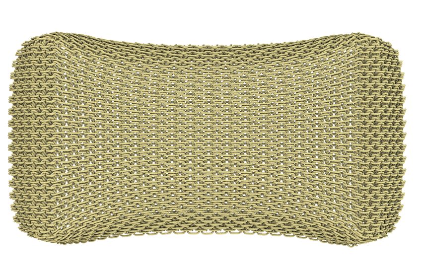
168:2    • Sperl, Narain, and Wojtan

  We also introduce an efficient way of linearizing the bending                     Example-Based & Mechanics-Aware Deformation. Our work ani-
response of yarn patterns in terms of stretching, and we propose a               mates yarn physics in real-time by interpolating from precomputed
way to clamp compression, allowing the user to tune the extent of                examples. Researchers also use example geometry to bias physics
yarn buckling. We implement the yarn deformation procedure as                    simulators toward preferred results [Gao et al. 2019; Koyama et al.
compute shaders on the GPU.                                                      2012; Martin et al. 2011; Schumacher et al. 2012; Wampler 2016].
                                                                                 Similar to Ma et al. [2008]’s interpolation of displacement textures
   Overview. We start by discussing related work in Section 2. Then              based on the deformation of a face mesh, we interpolate yarn ge-
we detail the two main stages of our method: data generation and                 ometry based on the deformation of a cloth mesh. Montazeri et al.
real-time displacement. Section 3 explains the data generation step              [2019] deform yarn cross-sections by learning a model from precom-
shown in Figure 3, where we optimize for the rest configuration                  puted simulations; our approach operates at one scale higher, by
of yarn patterns under a range of large-scale deformations, and                  animating the reconfiguration of yarn patterns based on a database
compute local displacements relative to these deformations. Sec-                 of precomputed examples.
tion 4 details the real-time displacement phase illustrated in Figure 4,            Researchers use similar ideas to add fine-scale wrinkle details to
where we map the precomputed yarn geometry onto a deforming                      a coarse cloth or flesh simulation. Procedural wrinkle methods rely
triangle mesh. Section 5 explores our method’s results. Section 6 dis-           on an underlying strain field [Hadap et al. 1999; Rohmer et al. 2010;
cusses limitations and advantages, and concludes with a summary                  Zuenko and Harders 2019] or explicit simulation of detail [Müller
and future work.                                                                 and Chentanez 2010], while data-driven wrinkle methods instead
                                                                                 train local operators or pose-dependent systems [Kavan et al. 2011;
                                                                                 Wang et al. 2010; Zurdo et al. 2012], with recent works building
2       RELATED WORK                                                             on recurrent or convolutional neural networks [Chentanez et al.
   Yarn-Level Cloth. Kaldor et al. [2008, 2010] first simulated cloth            2020; Jin et al. 2020; Santesteban et al. 2019; Vidaurre et al. 2020].
at the yarn level, and researchers later reduced collision detection             Our work assumes that the input cloth mesh animation already
costs with persistent sliding contacts [Cirio et al. 2014, 2015, 2016],          contains all cloth-scale features including wrinkles, and then adds
improved the bending model [Pizana et al. 2020], and handled con-                detail purely on a yarn scale.
tact between multiple layers of cloth [Sánchez-Banderas et al. 2020].
Leaf et al. [2018] developed a tool for designing yarn patterns under
tension.
                                                                                 3       DATA GENERATION
   Researchers recently combined yarn-level and mesh-level cloth                 We want our embedded yarn details to deform realistically, so we
simulators. Casafranca et al. [2020] enriched a mesh-based cloth                 prescribe their motion based on yarn-level simulations. This sec-
simulation with yarn-level simulation in regions of interest, and                tion describes the physics precomputation phase of our algorithm,
Sperl et al. [2020] used precomputed yarn patterns to develop a                  illustrated in Figure 3.
homogenized continuum material model. The latter use texture
maps to visualize yarn geometry, so the individual strands do not                3.1      Deformation Optimization
react to the deformation of the cloth. Our work enhances these
                                                                                 We use the method of Sperl et al. [2020] to simulate how each yarn
ideas by adding mechanics-aware yarn-level geometry to any mesh
                                                                                 pattern deforms. This method takes as input a particular yarn pattern
animation at negligible cost.
                                                                                 in an undeformed configuration (e.g. the “stockinette” pattern in
                                                                                 Figure 3), and a large-scale surface deformation encoded as the first
   Embedded Detail. A simple and effective way to give the illusion              I and second II fundamental forms. The method uses this large-scale
of detailed physics is to embed fine geometric detail into a coarser             deformation to define boundary conditions, and then optimizes for
control mesh. After the idea of dynamic free-form deformations                   the elastostatic equilibrium configuration of the yarn pattern. Sperl
were introduced by Faloutsos et al. [1997], researchers embedded                 et al. [2020] then reduced this geometric information down to a
geometric detail into animations of elasticity [Sifakis et al. 2007],            single scalar energy density used in a hyperelastic material model.
fracture [Muller et al. 2004], viscoelasticity [Wojtan and Turk 2008],           In contrast, we will use the yarn geometry directly.
fluids [Wojtan et al. 2009], and articulated characters [Rumman and                 We model yarns as discrete elastic rods [Bergou et al. 2010], rep-
Fratarcangeli 2016]. Researchers also use this idea to deform woven              resented as connected lists of vertices with positions x along the
yarn pattern geometry [Montazeri et al. 2020; Zhao et al. 2016]. Hoff-           centerline. Each edge also stores a twist angle θ and a reference di-
man et al. [2020] map detailed knit, crochet, and sequin geometry                rector d 1 .1 We concatenate positions and twists for each vertex into
onto cloth meshes with support for fly-away fibers. Stitch Meshes                                                           ⊤
                                                                                 a four-dimensional vector q = x ⊤ , θ , where θ corresponds
[Yuksel et al. 2012] used a simplified mechanical sheet model to de-
                                                                                 to one incident edge. (Note that the reference directors d 1 are not
form 3D yarn-level cloth models to reduce relaxation times. Because
                                                                                 degrees of freedom.)
these techniques apply coarse deformations to fine-scale geometry,
they cannot reproduce small-scale physical effects. Our method
addresses this in the context of yarn-level cloth, by displacing the
yarn geometry before mapping it onto the deformed mesh such that
the combined deformation actually captures the yarn-level physical               1 The subscript in d 1 refers to its definition as one of two reference directors: one for
effects.                                                                         the edge normal, and one for the edge binormal.

ACM Trans. Graph., Vol. 40, No. 4, Article 168. Publication date: August 2021.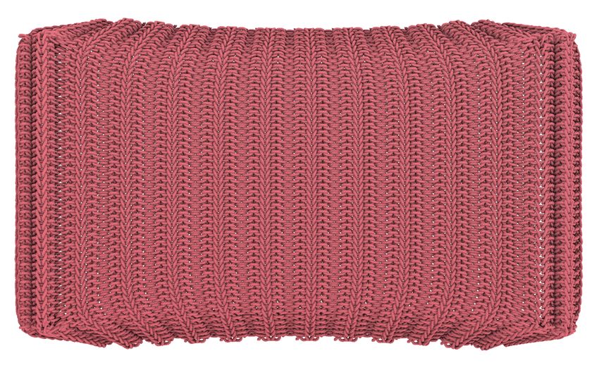
Mechanics-Aware Deformation of Yarn Pattern Geometry         •   168:3

             pattern Q                 deformed q                       optimized q                       pullback Q̂                         data ∆Q

Fig. 3. From left to right: We start with a periodic yarn pattern Q , and we apply a range of large-scale surface deformations to get the deformed state q. Using
the optimization method of Sperl et al. [2020], we optimize for the elastostatic rest shape q subject to the respective deformation. We then pull the resulting
geometry back into the undeformed material space to get Q̂ . Finally, we subtract the initial state to compute displacements ∆Q , building a mapping from
large-scale deformation to the associated local yarn-level deformation.

                        Q                     ∆Q               Q̂                                                           q

                                                                     material space           world space

Fig. 4. Our algorithm for animating yarn geometry in real-time: We start with undeformed yarn-level geometry Q tiled over a triangle in material space (left),
and we apply the appropriate material displacement ∆Q from the database to get deformed yarn geometry Q̂ (middle). This geometry is then mapped along
with the triangle to get the current world-space deformation q.

  We recall from [Sperl et al. 2020] that during the optimization                      Crucially for our application, we found that the optimization
the kinematics of yarn vertex positions are defined as                              of Sperl et al. [2020] contains a nullspace that allows yarns to
                                                                                    slide: a periodic yarn curve x(s) parametrized by s can slide by
                  x(X ) = x(X ) + ũ(X ),                                (1)        a parametric shift ∆s without changing its elastic energy E, i.e.
                  x(X ) = φ(X 1 , X 2 ) + X 3 n(X 1 , X 2 ).             (2)        E(x(s)) = E(x(s + ∆s)). Geometrically, such a shift corresponds
                                                                                    to tangential sliding of yarn while maintaining the same periodic
                                                                                    shape. To the optimizer any such state is equivalent, and the actual
Here, X = (X 1 , X 2 , X 3 )⊤ are the material-space coordinates of the
                                                                                    result may depend arbitrarily on numeric solver parameters. This
undeformed yarn pattern, with (X 1 , X 2 ) the orthogonal and periodic
                                                                                    nullspace does not affect the homogenized energies in [Sperl et al.
directions along the pattern and X 3 the height coordinate. x denotes
                                                                                    2020] by definition. However, interpolating between two shifted pa-
the large-scale deformation constructed from the input fundamental
                                                                                    rameterizations may produce completely different shapes, as shown
forms I and II, which encode in-plane and bending deformations
                                                                                    in Figure 5. In our experience, this nullspace creates distracting
respectively. From these fundamental forms, we construct the mid-
                                                                                    interpolation artifacts even for nearly-identical deformations. The
surface φ with normal n, as described in [Sperl et al. 2020] and in
                                                                                    problem remains as we sample the deformations more densely, man-
Appendix A, such that I = ∇φ ⊤ ∇φ and II = −∇φ ⊤ ∇n. We then
                                                                                    ifesting as sharp discontinuities in deformation space.
solve for the yarn configuration which minimizes elastic energy. The
                                                                                       We eliminate this parametric yarn sliding by adding a constraint
optimization variables are the fluctuations ũ, which describe local
                                                                                    to the optimization, effectively removing the nullspace. Specifically,
displacements relative to the large-scale deformation, and the twists
                                                                                    we fix one vertex per periodic yarn to remain on the boundary of
θ . Using Θ for undeformed twists, the concatenated coordinates
are undeformed Q = (X ⊤ , Θ)⊤ , large-scale-deformed q = (x ⊤ , Θ)⊤ ,
                                                                                    the pattern:
and optimized q = (x ⊤ , θ )⊤ . Here, we assume that twists Θ are                                                  ũ · (∇φ N ) = 0,                                (3)
unaffected by the large-scale mapping, which is true for pure in-
plane deformations. In general, bending may induce local twists that                where N is the undeformed normal to the respective pattern bound-
depend on II and the orientation of yarns relative to the curvature                 ary, either N = (1, 0)⊤ or N = (0, 1)⊤ . This sparse set of vertex
direction. In our experiments, we assume that this effect is small.                 constraints efficiently and effectively removes the aforementioned

                                                                                          ACM Trans. Graph., Vol. 40, No. 4, Article 168. Publication date: August 2021.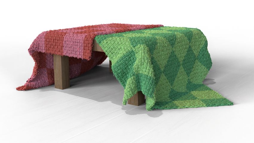
168:4 • Sperl, Narain, and Wojtan
Algorithm 1 Real-time Yarn Animation
Input: mesh animation, yarn pattern, displacement data ∆Q
Output: deformed yarn geometry q
1: procedure Animate Yarns
2: Q ← yarn pattern tiled over mesh
3: Each Frame:
4: compute I, II per face
5: interpolate I, II to mesh vertices
6: for each yarn vertex do ▷ on the GPU
7: interpolate I, II from mesh
Fig. 5. Top: Interpolating two periodic curves (left and right) that are iden- 8: compute linearized bending I(X 3 ) ▷ (7)
tical up to a shift in parametrization can result in arbitrary interpolated
9: clamp compression ▷ Section 4.3
shapes which look very different from the original data (center).
Bottom: Interpolating yarn geometry without accounting for sliding creates
10: compute strains s x , sa , sy ▷ (4)
unrealistic artifacts like self-collisions and floating loops (left); our sliding 11: look up displacements ∆Q ▷ Section 3.3
constraint eliminates these artifacts (right). 12: displace: Q̂ ← Q + ∆Q ▷ (8)
13: map: q ← (x(X̂ )⊤ , Θ̂)⊤ ▷ Section 4.5
14: end for
interpolation artifacts. This strategy allows us to find a physically 15: tessellate and render q ▷ Supplementary S2
realistic yarn shape for a given large-scale deformation described
16: end procedure
by I and II.
3.2 Sampling
Now that we can produce yarn geometry for a given deformation, Concatenating Q̂ = (X̂ ⊤ , θ )⊤ , we subtract the initial material
we want to precompute a series of representative samples and in- state to get displacements
terpolate them at runtime. I and II are each symmetric 2 × 2 ten-
sors, so parameterizing deformation by I and II directly yields a ∆Q = Q̂ − Q. (5)
6-dimensional function which is expensive to precompute, store,
Note that at the rest pose, I = Id, II = 0, and ∆Q = 0.
and read at runtime. We aim to reduce this dimensionality by pa-
To summarize, we can now build a database of material-space
rameterizing the deformation with as few variables as possible.
yarn displacements ∆Q for each vertex i of a pattern and for a range
Following Sperl et al. [2020], we reparameterize I as a 3-dimensional
of in-plane deformations j: ∆Q i (s x j , saj , sy j ). This database can be
function using the in-plane strains
interpreted as a grid of example deformations, or similarly as a 3D
p I12 p
s x = I11 − 1, sa = √ , sy = I22 − 1. (4) displacement texture per yarn vertex. Interpolating between these
I11 I22 samples takes a planar deformation s x j , saj , sy j and maps it to a
II can be parameterized similarly by introducing additional cur- yarn-level displacement map. Note that this will recover the exact
vature variables and increasing the dimensionality of the dataset. deformed yarn pattern for the strains sampled in the database and
However, we show in Section 4 that bending deformation can be approximate patterns for intermediate strains.
reasonably approximated in terms of stretching variables alone. This
strategy lets us sample the entire large-scale deformation space with 4 REAL-TIME DISPLACEMENT
only three variables s x , sa , and sy , significantly reducing memory Now that we have a database of yarn pattern displacements for a
and computation overhead. We sample these deformations on a range of deformations, we apply them to a yarn pattern tiled over an
regular 3D grid, and we discuss the performance, data size, and animating triangle mesh. In the following discussion, we denote Q
quality for different numbers of samples in Section 5. as the undeformed (material space) coordinates, Q̂ as the coordinates
deformed by local displacements, and q as the final world-space
3.3 Material-Space Displacements coordinates, as illustrated in Figure 4. Algorithm 1 outlines our
At runtime, our interpolated yarn geometry will be mapped onto a procedure.
deformed triangle mesh, where it will naturally inherit the deforma- As a precomputation, we
tion of its triangle (the mapping from material-space to world-space first create the initial un-
in Figure 4). Thus, we want to store all of the deformation except the X3
deformed yarn mesh cor-
large-scale deformation in our precomputation as material-space X2 responding to the unde-
displacements (the “pullback” column in Figure 3). formed triangle mesh (in-
To do this, we need to find the modified material space coordinates set). We generate a 2D back-
X̂ which give us our desired world-space deformations x when ground grid in the mesh’s
deformed by only the large-scale deformation x(X̂ ): in other words, X1 UV-coordinates with cells
find X̂ s.t. x = x(X̂ ). We perform this solve using Newton’s method the size of the periodic pattern, and we copy the yarn geometry into
and provide more details in Appendix B. every cell that overlaps an undeformed triangle. We then remove
ACM Trans. Graph., Vol. 40, No. 4, Article 168. Publication date: August 2021.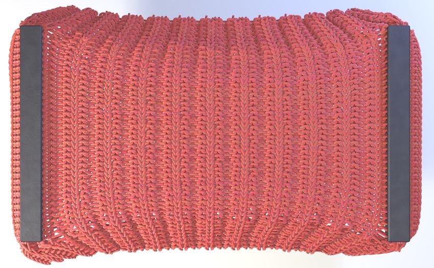
Mechanics-Aware Deformation of Yarn Pattern Geometry        •   168:5

yarn vertices that do not lie within a triangle and delete yarn frag-
ments shorter than a user-specified length for aesthetic purposes as
described in the supplementary (Section S1). Finally, we precompute
the material-space barycentric coordinates for each yarn vertex.

4.1   Mesh Strains
Each animation frame, we compute discrete fundamental forms for
each triangle as in [Sperl et al. 2020]:
                 I = F ⊤F ,                   II = F ⊤ Λ F ,             (6)    Fig. 6. Top: From left to right, a yarn pattern buckles into different config-
where F is the triangle deformation gradient and Λ is the triangle-             urations under increasing shearing deformation. Bottom: Adding a lower
averaged shape operator from [Grinspun et al. 2006]. We then dis-               bound λ min =0.7 to the eigenvalues of the in-plane deformation I allows a
tribute them to triangle vertices using modified Shepard weights                user to tune the extent of buckling during animation.
from Phong interpolation [James 2020], and finally interpolate them
to each yarn vertex.

4.2   Linearized Bending
As alluded to in Section 3.2, we can approximate the effect of bending
behavior by adding stretching and compression depending on the
surface curvature. We show in Appendix C.1 that we can enhance
                                                                                Fig. 7. The yarns of a rib pattern adapt to increased stretching from an initial
the first fundamental form with one that varies along the surface               state (left) until the limits of the precomputed data are reached (middle).
normal:                                                                         Deformation beyond the sample limits (right) do not result in further local
                           I(X 3 ) ≈ I − 2 X 3 II,                       (7)    displacements, but instead fall back to purely embedded deformation.

We illustrate this idea in the inset figure to the
right, which approximates the extruded volume
around a curved blue midsurface (top) with a            ≈
linearized volume that is stretched above and
compressed below the midsurface (bottom). We
compare this idea to other bending models in Section 5.
                                                                                Fig. 8. Barycentric embedding of yarn geometry may create sharp edges
                                                                                (center), whereas Phong deformation smooths out obvious mesh resolution
4.3   Compression Clamping                                                      artifacts (right).
Like most elastic materials, cloth buckles out of plane when com-
pressed. The chaotic nature of this buckling can make our yarn
optimization reach multiple visually distinct configurations that               this constant extrapolation will limit the local deformations while
do not vary smoothly over deformation space (Figure 6, top). Sperl              still inheriting large-scale deformations from the mesh embedding
et al. [2020] dealt with this issue regularizing the fit of their out-          (See Figure 7).
put energies. We similarly regularize compression by clamping the
eigenvalues of I to a lower bound before looking up the yarn dis-               4.5    World-Space Mapping
placement, which reduces buckling in a user-tunable way.
   Using the method of Deledalle et al. [2017], we set a minimum                To map the yarn vertices to world space x, we use:
value λ min for the eigenvalues of I(Z ). (Unless stated otherwise,                                x(X̂ ) = φ(X̂ 1 , X̂ 2 ) + X̂ 3 n(X̂ 1 , X̂ 2 ),             (9)
all of our experiments use λ min =0.8, where λ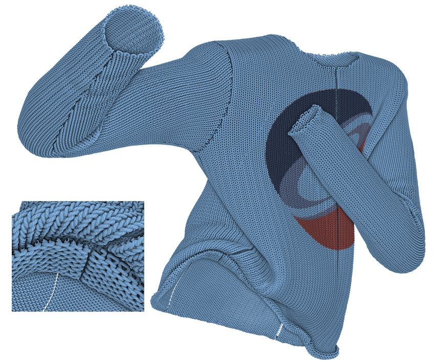
168:6    • Sperl, Narain, and Wojtan

                                                               ours

                                                               naive

Fig. 9. Comparison of our mechanics-aware yarn animation (top) against
naive embedding (bottom). The yarn geometry differs substantially on the
left, where the deformation is large.

                                                                                 Fig. 10. Different yarn patterns mapped onto a twisted cloth with our
4.6      Real-Time Rendering                                                     method react differently to the mesh deformation. The second row shows a
Computer graphics researchers have developed a number of algo-                   zoom and compares it to naive embedding in the third row. Our method
                                                                                 captures the subtle tightening in all cases, while the naive method results
rithms for rendering yarns and fibers [Montazeri et al. 2020, 2019;
                                                                                 in unrealistic gaps between yarns.
Wu and Yuksel 2017]. For the examples in this paper, we tessellate
the deformed yarns as cylindrical meshes in a geometry shader. We
approximate ply- and fiber-level detail with procedurally twistable
normal maps and ambient occlusion maps, and we approximate
volume conservation by locally rescaling yarn radii when they are
stretched. We provide the full rendering details in the supplementary
document Section S2.

5       RESULTS
We will now discuss examples generated by our mechanics-aware
yarn animation technique. Figure 9 shows how our algorithm com-
pares to a more typical embedded approach to animating yarn-level
geometry detail. Our method naturally reacts to the deformation of
the underlying cloth by causing loops to rearrange and tighten up
as the tension is increased. As a natural consequence, our approach
also reproduces the tendency of knitted and mesh fabrics to become
more transparent when stretched. Figure 10 shows how we can
easily apply different yarn-patterns to any cloth mesh, producing
visually distinct geometry which depends on both the deformations
of the mesh and the precomputed yarn mechanics. Our method can
add yarn-level details onto any deforming triangle mesh: examples
in this paper use deforming cloth meshes from ArcSim [Narain
et al. 2013, 2012], position-based dynamics [Müller et al. 2007], and            Fig. 11. Comparison of yarns animated with our method applied to a pre-
Blender [2020].                                                                  computed cloth simulation (left) against full yarn-level simulation (right,
   We enhance an offline cloth simulation solver which reproduces                courtesy of Sperl et al. [2020]). Our yarn level deformations differ the most
the large-scale effects of knitted garments [Sperl et al. 2020]. Fig-            where the triangle-level cloth simulation is least accurate.
ure 11 compares this approximation to ground-truth yarn-level
simulations, yielding visually plausible recreations of the local pat-                                 :


tern deformation. We note that the accuracy of our method highly
depends on the accuracy of the underlying triangle deformation, so
we see higher discrepancy where the FEM cloth simulation deviates
from yarn-level simulation.
   We also used our approach to add yarn-level details to a position-
based dynamics cloth solver [Bender et al. 2015], to approximate
                                                                                 Fig. 12. We use position-based dynamics to simulate a sock being pulled
yarn-level cloth simulation in real-time. Figure 12 shows how a user
                                                                                 over a foot in real-time, where the user can interactively control the force.
can perform an interactive dressing operation by pulling a knitted
sock onto a foot. Note that our method still produces plausible yarn-
level deformations, despite the fact that the default position-based               Figure 13 shows we can render our yarn geometry offline to
elastic material model is quite far from a model derived from yarn               produce higher quality path-traced scenes with “fuzz” from a pro-
physics.                                                                         cedural particle system. Figure 14 shows how our GPU-based yarn

ACM Trans. Graph., Vol. 40, No. 4, Article 168. Publication date: August 2021.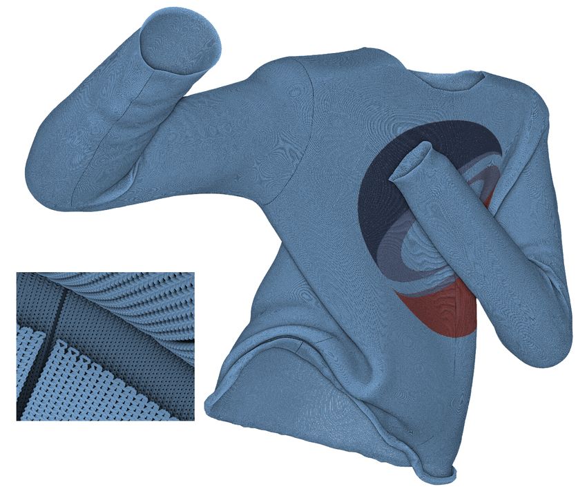
Mechanics-Aware Deformation of Yarn Pattern Geometry        •   168:7

                                                                                                                                                                  2R

Fig. 13. Two examples of our yarn geometry that were rendered offline
using path tracing and hair particles.
                                                                                                                                                                  0
                                                                                   Fig. 15. Comparison of different data sampling densities. The top and bot-
                                                                                   tom rows show results generated with 5 × 5 × 5 and 31 × 31 × 31 samples
                                                                                   respectively. In the top images, we color-code the L 2 error in vertex positions
                                                                                   between the coarse and fine model, compared to the yarn radius R; red color
                                                                                   corresponds to a larger difference. The coarse model produces plausible
                                                                                   geometry even in the presence of larger errors.

                                                                                      On the other hand, a large number of database samples led to
                                                                                   unwanted noise in the animations, like sudden ‘pops’ from one
                                                                                   configuration to another, instead of gradual ones. We believe our
Fig. 14. Our method scales favorably with increasing yarn density. We              observations are consistent with those of Sperl et al. [2020], who
deform yarn geometry for a sweater with 0.8 million vertices at well over          noted that a dense sampling rate (especially in the compressive
100 FPS (left), and a sweater with 42.7 million vertices at over 14 FPS (right).   regime where fabric buckles chaotically) required explicit filtering
                                                                                   to remove high-frequency noise. In our case, simply removing sam-
                                                                                   ples from the database acts as an effective low-pass filter, and our
displacement algorithm allows for the animation of garments with                   compression clamping technique strongly reduces popping.
millions of individual yarn vertices at interactive rates. Please refer               The complexity of our yarn database has only a small affect on
to our supplementary video for additional highly detailed results.                 runtime. Table 2 relates the number of precomputed yarn-level sim-
For reproducibility, we release the source code and data used to                   ulations in our database to the memory and runtime of our method.
generate our results (https://git.ist.ac.at/gsperl/MADYPG).                        Notably, a 238× increase in database size caused a proportional
                                                                                   increase in memory but only a 2.8× increase in runtime. Unless
   Performance. We ran our method on a desktop computer with an                    stated otherwise, the results shown in this paper use datasets of 93
Intel Core i7-7820X processor and an NVIDIA GeForce GTX 1080                       samples sampled uniformly over the ranges s x , sy ∈ [−0.2, 1.0] and
Ti graphics card and gathered performance statistics. Table 1 breaks               sa ∈ [−0.7, 0.7].
down the computational cost of our algorithm for each of the various
examples in this paper. Almost all examples in this paper perform                      Bending Models. Finally, we compare the effect of our linearized
both geometry generation and rendering in real-time (well over 60                  bending approximation in Figure 16. We compare our linearized
fps). To stress-test our method, we created the knitted sweater in                 model described in Section 4.2 to a bending model that explicitly
Figure 14 (right), which has more than 40 million yarn vertices and                captures combined stretching and bending. (See Appendix C for
generates yarn geometry at over 14 fps. The total time including                   details on these comparison models, and see our supplementary
rendering (depending on the complexity of the renderer and the                     videos for an animated version of this and similar tests.) First of all,
amount of geometry per pixel due to camera zoom) is around 4 fps                   we found that the importance of bending depends on the knit pattern:
for this example. Please see our submission video for more detailed                “thick” patterns like the rib (Figure 10 red, center) exhibit more
demonstrations of our method.                                                      differences than nearly planar ones like the stockinette (Figure 10
                                                                                   blue, right). The further away the geometry is from the surface φ,
   Dataset Size. The number of samples in our precomputed yarn                     the more it is locally stretched or compressed by bending. Second,
database only modestly affects the visual quality of the animation.                even for a thick pattern, the differences between the two models are
Figure 15 shows a deformed rib pattern with a varying number of                    minor and localized to regions of strong curvature. Most importantly,
database samples and a visualization of the associated interpolation               the linearized model is much more efficient — when comparing CPU-
error. We also provide animations with several sampling densities                  based implementation, our linearized model ran roughly 8× faster.
in our supplementary material. In practice, we found that a small                      An extra benefit of the linearized bending model is that it trans-
number of samples was sufficient to capture strong effects like                    forms bending-induced buckling into compression, which can be
loops tightening under tension, and we noticed surprisingly few                    filtered with our compression clamping algorithm (Section 4.3). Oth-
obvious interpolation errors (like interpolated threads leading to                 erwise, it would be non-trivial to filtering both compression- and
self-collisions).                                                                  bending-related buckling in a compatible and coherent manner.

                                                                                         ACM Trans. Graph., Vol. 40, No. 4, Article 168. Publication date: August 2021.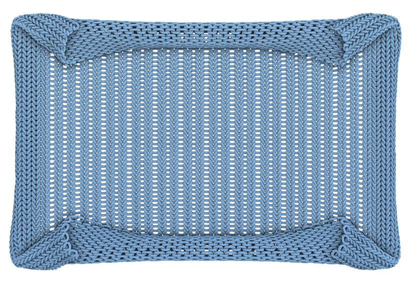
168:8   • Sperl, Narain, and Wojtan

Table 1. Performance breakdown of results in this paper. From left to right, we list: the respective figure, the number of animated yarn vertices and average
per-frame times of mesh strain computation (Section 4.1), data look-up and local yarn displacements (Sections 4.2 to 4.4), and embedded world-space mapping
(Section 4.5). The mesh stage is implemented on the CPU, whereas yarn displacement and mapping are implemented on the GPU. In comparison, the
CPU-implemented position-based dynamics step for the sock example averaged to 19.24 ms.

                        animation                                                # vertices       strainsCPU   displacementGPU      mappingGPU
                        sleeve                                      Fig. 9              94k          1.02 ms            0.13 ms          0.10 ms
                        patterns (averaged)                        Fig. 10              82k          0.82 ms            0.09 ms          0.07 ms
                        honeycomb stretch                     Fig. 11 top               74k          0.61 ms            0.08 ms          0.07 ms
                        rib stretch                        Fig. 11 center              154k          0.77 ms            0.16 ms          0.12 ms
                        stockinette stretch               Fig. 11 bottom               119k          0.59 ms            0.12 ms          0.11 ms
                        stockinette sweater                   Fig. 14 left             862k          2.59 ms            0.81 ms          0.66 ms
                        fine stockinette sweater            Fig. 14 right             42.7M          2.59 ms           35.34 ms         27.68 ms
                        rib twist                             Fig. 13 left             433k          0.38 ms            0.51 ms          0.38 ms
                        table cloth                         Fig. 13 right              130k          1.50 ms            0.16 ms          0.13 ms
                        sock                                       Fig. 12             139k           7.5 ms            0.14 ms          0.11 ms

Table 2. Comparison of rib pattern displacement data for different dataset
sizes. “generation” refers to the time needed to precompute the data,
and “displacement” refers to the per-frame time of computing Q̂ = Q +
∆Q (s x , s a , s z ) on a representative sweater animation with 1.8 million yarn
vertices.

                                                                                              Fig. 17. Approximating a seam by folding one piece of cloth over another
        # samples          memory        generation       displacement
                                                                                              on the mesh-level, rather than the thread level.
        53 = 125            0.7 MB          2.2 min               1.58 ms
        93 = 729            4.2 MB         12.7 min               1.82 ms
        153 = 3375         19.2 MB         59.8 min               2.30 ms
        313 = 29791       169.7 MB        533.6 min               4.35 ms
                                                                                              6     DISCUSSION
                                                                                              Because our method is based on geometric interpolation of yarn
                                                                                              vertices rather than an exact simulation of yarn-level geometry, it
                                                                                 2R           cannot exactly reproduce all yarn-level effects. Our method funda-
                                                                                              mentally assumes that the deformations sampled in the database are
                                                                                              representative of the deformations in the online simulation. Because
                                                                                              our per-vertex mesh strains only communicate deformations on the
                                                                                              scale of a single triangle, the method will not be able to accurately re-
                                                                                              act to fine-scale collision events like pulling on an individual thread.
                                                                                              Similarly, our method relies on the mesh simulation to handle colli-
                                                                                              sions; it will not exactly resolve object collisions on the level of the
                                                                                              individual thread, and it will not exactly resolve collisions for very
                                                                                 0            thick fabrics if the mesh is modeled as infinitely thin.
                                                                                                 Our database currently also ignores time-dependent effects like
Fig. 16. We compare our linearized bending model against a model incorpo-                     hysteresis and damping, so repeating a mesh deformation will yield
rating bending strains explicitly on an animated knit sweater. We measure
                                                                                              exactly the same fine-scale yarn arrangements. Our method interpo-
the difference between the models as the L 2 norm of the difference in yarn
                                                                                              lates the precomputed behaviors of a periodic yarn pattern, so we
vertex positions, and we color code them relative to the yarn radius R; red
color corresponds to a larger difference. The cut-outs show how knit loops                    cannot yet simulate clothes consisting of completely aperiodic or
appear to tighten more with the linearized model (top) than the explicit                      disorganized threads, and it will be significantly more expensive to
bending model (bottom).                                                                       simulate ornate patterns with a large number of yarn vertices. We
                                                                                              also do not yet handle non-periodic connections between different
                                                                                              patches of cloth, so our method cannot yet sew together seams on
                                                                                              the individual thread level. However, we can approximate larger
                                                                                              seams by folding a piece of thin fabric over itself (Figure 17).
   We animated most of the figures and concepts in this paper and                                On the other hand, our geometric approximation affords us a
included them in a supplementary video .zip file, which is separate                           number of advantages and leads to a few novel challenges. The data-
from this paper’s main explanatory submission video.                                          driven approach completely avoids the expense of online collision

ACM Trans. Graph., Vol. 40, No. 4, Article 168. Publication date: August 2021.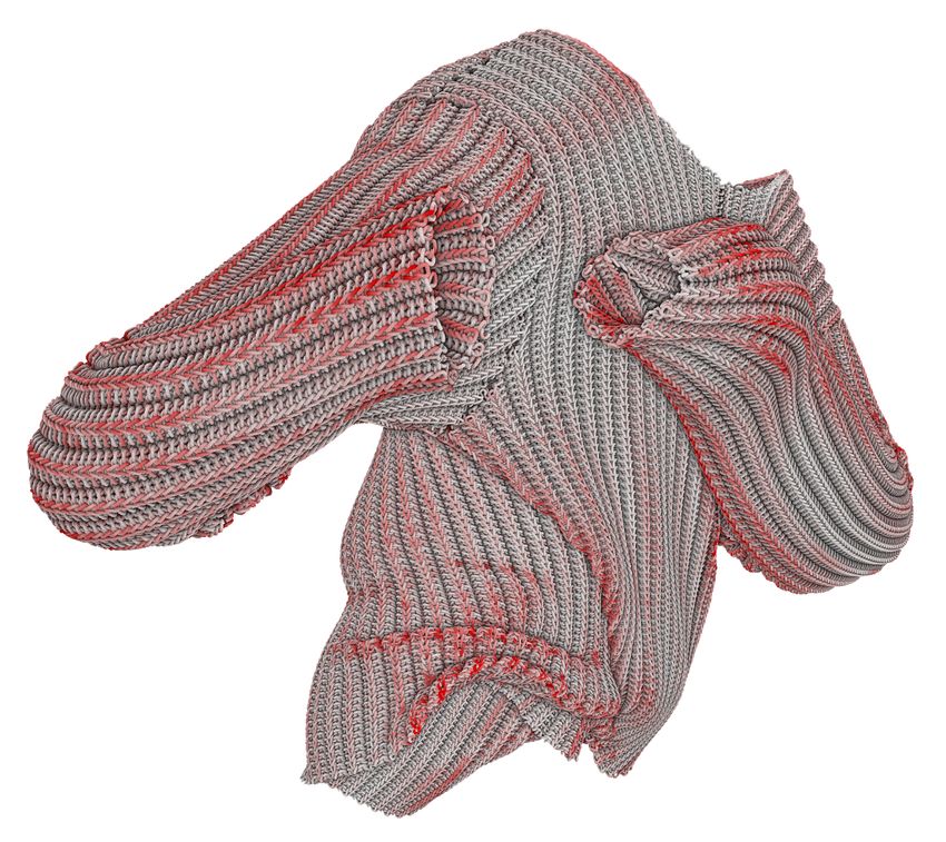
Mechanics-Aware Deformation of Yarn Pattern Geometry          •   168:9

handling, and its exploitation of periodic structures avoids redun-                      Gabriel Cirio, Jorge Lopez-Moreno, David Miraut, and Miguel A Otaduy. 2014. Yarn-
dant computations resulting from structurally similar yarn patterns.                        level simulation of woven cloth. ACM Transactions on Graphics (TOG) 33, 6 (2014),
                                                                                            1–11.
The method cuts the complexity of brute-force yarn level cloth by                        Gabriel Cirio, Jorge Lopez-Moreno, and Miguel A Otaduy. 2015. Efficient simulation
several orders of magnitude, and as far as we know, our method                              of knitted cloth using persistent contacts. In Proceedings of the 14th ACM SIG-
                                                                                            GRAPH/Eurographics Symposium on Computer Animation. 55–61.
is the only way to simulate millions of yarn vertices at interactive                     Gabriel Cirio, Jorge Lopez-Moreno, and Miguel A Otaduy. 2016. Yarn-level cloth
rates. The interpolative nature of the approach also guarantees un-                         simulation with sliding persistent contacts. IEEE Transactions on Visualization and
conditional numerical stability, so the method cannot blow up even                          Computer Graphics 23, 2 (2016), 1152–1162.
                                                                                         Blender Online Community. 2020. Blender - a 3D modelling and rendering package.
in unrealistic video game environments. The speed and detail of our                         Blender Foundation, Stichting Blender Foundation, Amsterdam. http://www.blender.
approach for animating knitted garments also creates new research                           org
challenges: zooming out from a pattern made of millions of threads                       Charles-Alban Deledalle, Loic Denis, Sonia Tabti, and Florence Tupin. 2017. Closed-
                                                                                            form expressions of the eigen decomposition of 2 x 2 and 3 x 3 Hermitian matrices.
can cause aliasing patterns when many of them occupy a single                               (2017).
pixel, potentially requiring novel geometry anti-aliasing techniques                     Petros Faloutsos, Michiel Van De Panne, and Demetri Terzopoulos. 1997. Dynamic
                                                                                            free-form deformations for animation synthesis. IEEE Transactions on Visualization
in the future.                                                                              and Computer Graphics 3, 3 (1997), 201–214.
                                                                                         Lin Gao, Yu-Kun Lai, Jie Yang, Zhang Ling-Xiao, Shihong Xia, and Leif Kobbelt. 2019.
   Conclusion. We have presented a method for deforming yarn                                Sparse data driven mesh deformation. IEEE transactions on visualization and com-
patterns in a mechanics-aware manner. It reproduces characteristic                          puter graphics (2019).
                                                                                         Eitan Grinspun, Yotam Gingold, Jason Reisman, and Denis Zorin. 2006. Computing
yarn-level cloth behaviors like knitted loops that tighten when                             discrete shape operators on general meshes. In Computer Graphics Forum, Vol. 25.
the fabric is stretched. We introduced practical heuristics such as                         Wiley Online Library, 547–556.
linearizing bending and limiting buckling, which make the method                         Sunil Hadap, E Bongarter, Pascal Volino, and Nadia Magnenat-Thalmann. 1999. An-
                                                                                            imating wrinkles on clothes. In Proceedings Visualization’99 (Cat. No. 99CB37067).
significantly more efficient and tunable by artists. The method is                          IEEE, 175–523.
lightweight and GPU-parallelizable, so it is capable of animating                        Jonathan Hoffman, Matt Kuruc, Junyi Ling, Alex Marino, George Nguyen, and Sasha
millions of yarn vertices at real-time rates.                                               Ouellet. 2020. Hypertextural Garments on Pixar’s Soul. In ACM SIGGRAPH 2020
                                                                                            Talks. Association for Computing Machinery, Article 75.
   In the future, we are interested in new research challenges intro-                    Doug L James. 2020. Phong deformation: a better C0 interpolant for embedded defor-
duced by the massive scale of these yarn simulations. The method                            mation. ACM Transactions on Graphics (TOG) 39, 4 (2020), 56–1.
                                                                                         Ning Jin, Yilin Zhu, Zhenglin Geng, and Ronald Fedkiw. 2020. A Pixel-Based Framework
could further benefit from level-of detail approaches simplifying                           for Data-Driven Clothing. In Computer Graphics Forum, Vol. 39. Wiley Online Library,
yarn geometry where it is not visible. Our technique might also be                          135–144.
useful for research into deformation-dependent microfacet render-                        Jonathan M Kaldor, Doug L James, and Steve Marschner. 2008. Simulating knitted cloth
                                                                                            at the yarn level. In ACM Transactions on Graphics (TOG). Vol. 27. 65.
ing or anti-aliasing techniques, for smoothly replacing extremely                        Jonathan M Kaldor, Doug L James, and Steve Marschner. 2010. Efficient yarn-based
dense yarn geometry with an analytic or data-driven shading model.                          cloth with adaptive contact linearization. In ACM Transactions on Graphics (TOG),
                                                                                            Vol. 29. ACM, 105.
ACKNOWLEDGMENTS
                                                                                         Ladislav Kavan, Dan Gerszewski, Adam W Bargteil, and Peter-Pike Sloan. 2011. Physics-
                                                                                            inspired upsampling for cloth simulation in games. In ACM SIGGRAPH 2011 papers.
                                                                                            1–10.
We wish to thank the anonymous reviewers and the members of the                          Josef Kiendl, Ming-Chen Hsu, Michael CH Wu, and Alessandro Reali. 2015. Isogeometric
Visual Computing Group at IST Austria for their valuable feedback.                          Kirchhoff–Love shell formulations for general hyperelastic materials. Computer
We also thank Seddi Labs for providing the garment model with                               Methods in Applied Mechanics and Engineering 291 (2015), 280–303.
                                                                                         Yuki Koyama, Kenshi Takayama, Nobuyuki Umetani, and Takeo Igarashi. 2012.
fold-over seams.                                                                            Real-time example-based elastic deformation. In Proceedings of the ACM SIG-
   This research was supported by the Sci-                                                  GRAPH/Eurographics Symposium on Computer Animation. 19–24.
entific Service Units (SSU) of IST Austria                                               Jonathan Leaf, Rundong Wu, Eston Schweickart, Doug L James, and Steve Marschner.
                                                                                            2018. Interactive design of periodic yarn-level cloth patterns. ACM Transactions on
through resources provided by Scientific                                                    Graphics (TOG) 37, 6 (2018), 1–15.
Computing. This project has received funding from the European                           Wan-Chun Ma, Andrew Jones, Jen-Yuan Chiang, Tim Hawkins, Sune Frederiksen,
                                                                                            Pieter Peers, Marko Vukovic, Ming Ouhyoung, and Paul Debevec. 2008. Facial
Research Council (ERC) under the European Union’s Horizon 2020
                                                                                            performance synthesis using deformation-driven polynomial displacement maps.
research and innovation programme under grant agreement No.                                 ACM Transactions on Graphics (TOG) 27, 5 (2008), 1–10.
638176. Rahul Narain is supported by a Pankaj Gupta Young Fac-                           Sebastian Martin, Bernhard Thomaszewski, Eitan Grinspun, and Markus Gross. 2011.
                                                                                            Example-based elastic materials. In ACM SIGGRAPH 2011 papers. 1–8.
ulty Fellowship and a gift from Adobe Inc.                                               Zahra Montazeri, Søren B Gammelmark, Shuang Zhao, and Henrik Wann Jensen. 2020.
                                                                                            A practical ply-based appearance model of woven fabrics. ACM Transactions on
REFERENCES                                                                                  Graphics (TOG) 39, 6 (2020), 1–13.
                                                                                         Zahra Montazeri, Chang Xiao, Yun Fei, Changxi Zheng, and Shuang Zhao. 2019.
David Baraff and Andrew Witkin. 1998. Large steps in cloth simulation. In Proceedings       Mechanics-Aware Modeling of Cloth Appearance. IEEE transactions on visualization
   of the 25th annual conference on Computer graphics and interactive techniques. ACM,      and computer graphics 27, 1 (2019), 137–150.
   43–54.                                                                                Matthias Müller and Nuttapong Chentanez. 2010. Wrinkle Meshes.. In Symposium on
Jan Bender, Matthias Müller, and Miles Macklin. 2015. Position-Based Simulation             Computer Animation. Madrid, Spain, 85–91.
   Methods in Computer Graphics.. In Eurographics (tutorials). 8.                        Matthias Müller, Bruno Heidelberger, Marcus Hennix, and John Ratcliff. 2007. Position
Miklós Bergou, Basile Audoly, Etienne Vouga, Max Wardetzky, and Eitan Grinspun.             based dynamics. Journal of Visual Communication and Image Representation 18, 2
   2010. Discrete viscous threads. ACM Transactions on Graphics (TOG) 29, 4 (2010),         (2007), 109–118.
   1–10.                                                                                 Matthias Muller, Matthias Teschner, and Markus Gross. 2004. Physically-based simula-
Juan J Casafranca, Gabriel Cirio, Alejandro Rodríguez, Eder Miguel, and Miguel A            tion of objects represented by surface meshes. In Proceedings Computer Graphics
   Otaduy. 2020. Mixing yarns and triangles in cloth simulation. In Computer Graphics       International, 2004. IEEE, 26–33.
   Forum, Vol. 39. Wiley Online Library, 101–110.                                        Rahul Narain, Tobias Pfaff, and James F O’Brien. 2013. Folding and crumpling adaptive
Nuttapong Chentanez, Miles Macklin, Matthias Müller, Stefan Jeschke, and Tae-Yong           sheets. ACM Transactions on Graphics (TOG) 32, 4 (2013), 51.
   Kim. 2020. Cloth and skin deformation with a triangle mesh based convolutional        Rahul Narain, Armin Samii, and James F O’Brien. 2012. Adaptive anisotropic remeshing
   neural network. In Computer Graphics Forum, Vol. 39. Wiley Online Library, 123–          for cloth simulation. ACM Transactions on Graphics (TOG) 31, 6 (2012), 152.
   134.

                                                                                                ACM Trans. Graph., Vol. 40, No. 4, Article 168. Publication date: August 2021.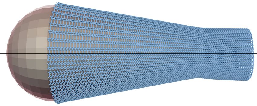
168:10 • Sperl, Narain, and Wojtan
José M Pizana, Alejandro Rodríguez, Gabriel Cirio, and Miguel A Otaduy. 2020. A Then, with
Bending Model for Nodal Discretizations of Yarn-Level Cloth. In Computer Graphics
Forum, Vol. 39. Wiley Online Library, 181–189. 2
Õ 2
Õ p
Damien Rohmer, Tiberiu Popa, Marie-Paule Cani, Stefanie Hahmann, and Alla Sheffer. a= n 1,α X α , b= n 2,α X α , r = a2 + b 2 , (12)
2010. Animation wrinkling: augmenting coarse cloth simulations with realistic-
α =1 α =1
looking wrinkles. ACM Transactions on Graphics (TOG) 29, 6 (2010), 1–8.
Nadine Abu Rumman and Marco Fratarcangeli. 2016. State of the Art in Skinning we compute R(X 1 , X 2 ) as
Techniques for Articulated Deformable Characters.. In VISIGRAPP (1: GRAPP). 200–
212. 1 − 1 a 2 sinc(r /2)2
Rosa M Sánchez-Banderas, Alejandro Rodríguez, Héctor Barreiro, and Miguel A Otaduy. 2 − 12 ab sinc(r /2)2 a sinc(r )
R = − 12 ab sinc(r /2)2 b sinc(r ) .
2020. Robust eulerian-on-lagrangian rods. ACM Transactions on Graphics (TOG) 39, 1 − 21 b 2 sinc(r /2)2 (13)
4 (2020), 59–1.
−a sinc(r ) −b sinc(r ) cos(r )
Igor Santesteban, Miguel A Otaduy, and Dan Casas. 2019. Learning-Based Animation
of Clothing for Virtual Try-On. In Computer Graphics Forum, Vol. 38. Wiley Online
Library, 355–366. Finally, we solve for φ with the Poisson equation ∇2φ = ∇ · RS
Christian Schumacher, Bernhard Thomaszewski, Stelian Coros, Sebastian Martin, and natural boundary conditions discretized on a grid. For further
Robert Sumner, and Markus Gross. 2012. Efficient simulation of example-based details, we refer to the paper and supplementary document of [Sperl
materials. In Proceedings of the 11th ACM SIGGRAPH/Eurographics conference on
Computer Animation. Citeseer, 1–8. et al. 2020]. The sliding constraint (3) is thus ũ · (RS N ) = 0.
Eftychios Sifakis, Tamar Shinar, Geoffrey Irving, and Ronald Fedkiw. 2007. Hybrid simu-
lation of deformable solids. In Proceedings of the 2007 ACM SIGGRAPH/Eurographics
symposium on Computer animation. 81–90.
B PULLBACK INTO MATERIAL SPACE
Georg Sperl, Rahul Narain, and Chris Wojtan. 2020. Homogenized Yarn-Level Cloth. Here, we detail the Newton iteration to transform optimized yarn
ACM Transactions on Graphics (TOG) 39, 4 (2020).
Demetri Terzopoulos, John Platt, Alan Barr, and Kurt Fleischer. 1987. Elastically de-
geometry from Section 3 back into material space. The goal is to
formable models. In Proceedings of the 14th annual conference on Computer graphics find X̂ s.t. x = x(X̂ ), which we do using Newton’s method on
and interactive techniques. 205–214. f (X̂ ) = x − x(X̂ ), for which we need the gradient ∇ f .
Raquel Vidaurre, Igor Santesteban, Elena Garces, and Dan Casas. 2020. Fully Convolu-
tional Graph Neural Networks for Parametric Virtual Try-On. In Computer Graphics The mapping x is defined as
Forum, Vol. 39. Wiley Online Library, 145–156.
Kevin Wampler. 2016. Fast and reliable example-based mesh IK for stylized deformations. x(X̂ ) = φ(X̂ 1 , X̂ 2 ) + X̂ 3 n(X̂ 1 , X̂ 2 ), (14)
ACM Transactions on Graphics (TOG) 35, 6 (2016), 1–12.
Huamin Wang, Florian Hecht, Ravi Ramamoorthi, and James F O’Brien. 2010. Example- where φ is the deformed midsurface and n its normal. Its gradient is
based wrinkle synthesis for clothing animation. In ACM SIGGRAPH 2010 papers.
∇x(X̂ ) = ∇φ(X̂ 1 , X̂ 2 ) + X̂ 3 ∇n(X̂ 1 , X̂ 2 ), n(X̂ 1 , X̂ 2 ) .
1–8.
(15)
Chris Wojtan, Nils Thürey, Markus Gross, and Greg Turk. 2009. Deforming meshes
that split and merge. In ACM SIGGRAPH 2009 papers. 1–10.
Chris Wojtan and Greg Turk. 2008. Fast viscoelastic behavior with thin features. In By definition (see [Sperl et al. 2020]) we have
ACM SIGGRAPH 2008 papers. 1–8.
Kui Wu and Cem Yuksel. 2017. Real-time fiber-level cloth rendering. In Proceedings of ∇φ = RS, (16)
the 21st ACM SIGGRAPH Symposium on Interactive 3D Graphics and Games. 1–8.
Cem Yuksel, Jonathan M Kaldor, Doug L James, and Steve Marschner. 2012. Stitch and we compute ∇n with (11). The Newton iterations are
meshes for modeling knitted clothing with yarn-level detail. ACM Transactions on
Graphics (TOG) 31, 4 (2012), 1–12. X̂ i+1 = X̂ i − ∇ f (X̂ i )−1 f (X̂ i ) (17)
Shuang Zhao, Fujun Luan, and Kavita Bala. 2016. Fitting procedural yarn models for
realistic cloth rendering. ACM Transactions on Graphics (TOG) 35, 4 (2016), 1–11.
Evgeny Zuenko and Matthias Harders. 2019. Wrinkles, Folds, Creases, Buckles: Small- starting from the rest configuration X̂ 0 = X .
Scale Surface Deformations as Periodic Functions on 3D Meshes. IEEE Transactions In our experiments, the iterations converge to a fraction of the
on Visualization and Computer Graphics (2019). yarn radius within three iterations and the cost is negligible com-
Javier S Zurdo, Juan P Brito, and Miguel A Otaduy. 2012. Animating wrinkles by
example on non-skinned cloth. IEEE Transactions on Visualization and Computer pared to the elastostatic optimization. For pure
√ in-plane
deforma-
Graphics 19, 1 (2012), 149–158. I 0
tions, II = 0, and thus R = Id and ∇ f = − , simplifying
0 1
A OPTIMIZATION MID-SURFACE the pullback into the constant expression
√ −1
The fundamental forms I and II define the midsurface φ used in the
I 0
X̂ = X + ũ. (18)
optimization of Section 3. We construct φ like Sperl et al. [2020] 0 1
by solving for ∇φ ≈ RS in the least-squares sense (with ∇φ = RS
exactly for single curvature). To do so, we compute a rotation R C BENDING MODELS
describing curvature and an in-plane deformation matrix S from We briefly outline the two bending models we experimented with:
the two input fundamental forms I and II. The 3 × 2 matrix S is a 4D combination of in-plane and bending deformations (19), and
computed from the principal square root of I as the linearization of bending as stretching (22).
√ Due to tileability constraints, Sperl et al. [2020] only generate
I
S= . (10) data for singly curved deformations and split the contributions of
0 0 general bending onto data sampled for bending along either the
X 1 or X 2 directions. We apply the same idea to define our “ground-
To compute the rotation, we first compute normal derivatives truth” bending model. For brevity, we write s = (s x , sa , sy ). Then,
√ −⊤ we compute two sets of data for combined in-plane deformation
n 1,1 n 1,2 with the two bending directions: ∆Q X 1 (s, λ) and ∆Q X 2 (s, λ). With
∇n = =− I II. (11)
n 2,1 n 2,2 the eigenvalues λ 1 and λ 2 of II and the cosine c of the angle between
ACM Trans. Graph., Vol. 40, No. 4, Article 168. Publication date: August 2021.Mechanics-Aware Deformation of Yarn Pattern Geometry • 168:11
the X 1 axis and the eigenvector corresponding to λ 1 , we distribute C.1 Linearized Bending
the bending contributions to get For a thin shell represented by a midsurface φ with normal n, its
∆Q(s, II) = c 2 ∆Q X 1 (s, λ 1 ) + (1 − c 2 ) ∆Q X 1 (s, λ 2 ) full domain is
+ c 2 ∆Q X 2 (s, λ 2 ) + (1 − c 2 ) ∆Q X 2 (s, λ 1 ) (19) x = φ + h n, (20)
− ∆Q X 1 (s, 0) with the normal coordinate h ∈ [−H /2, H /2] for shell thickness H .
Its right Cauchy-Green deformation tensor is
Since both datasets include the displacements caused by pure in-
plane deformations λ 1 = λ 2 = 0, we have to subtract these displace- ∇x ⊤ ∇x = ∇φ ⊤ ∇φ + h (∇φ ⊤ ∇n + ∇n⊤ ∇φ) + O(h 2 ), (21)
ments once to avoid double counting. This model exactly reproduces which can be interpreted as a first fundamental form I(h) depending
the data samples for bending aligned with either X 1 or X 2 . However, quadratically on h. The quadratic term is commonly neglected (e.g.
it requires five 4D-texture look-ups and is thus much more expen- [Kiendl et al. 2015]). Additionally, we see that ∇φ ⊤ ∇φ = I and
sive than the linearized model requiring only a single 3D-texture similarly ∇φ ⊤ ∇n = ∇n ⊤ ∇φ = −II are the fundamental forms of φ.
look-up. For the speed comparison mentioned in Section 5, we used As a result, we get the linearized expression
two sets of 94 samples for the 4D model and 93 samples for the lin-
earized model. The linearized model was still 7× faster even when I(h) ≈ I − 2 h II. (22)
increasing its sample density to 153 . Then, with precomputed data ∆Q s (s) for in-plane deformations s,
the linearized bending model is
∆Q(I, II) = ∆Q s (s(I − 2 h II)). (23)
ACM Trans. Graph., Vol. 40, No. 4, Article 168. Publication date: August 2021.You can also read