Determining wind and snow loads for solar panels - America's Authority on Solar
←
→
Page content transcription
If your browser does not render page correctly, please read the page content below
determining wind and snow
loads for solar panels

America’s Authority on Solar
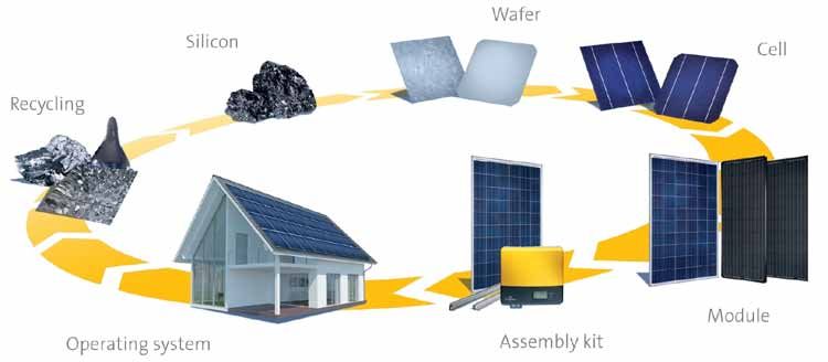
Determining wind and snow loads for solar panels                                                                                                1

introduction
As one of the largest and most established vertically integrated photovoltaic
(PV) manufacturers on the planet, SolarWorld is intimately involved with every
step of the solar PV value chain from raw silicon to installed systems to end of
life recycling. This complete knowledge base combined with our extensive
history provide the critical insight required to lead the solar industry on
technical topics.

The purpose of this paper is to discuss the mechanical                            SolarWorld modules have been tested according
design of photovoltaic systems for wind and snow                                  to UL and IEC standards and the maximum design
loads in the United States, and provide guidance                                  loads for various mounting methods are provided
using The American Society of Civil Engineers (ASCE)                              in the Sunmodule User Instruction guide. Once we
Minimum Design Loads for Buildings and Other                                      have gone through the sample calculations and
Structures, ASCE 7-05 and ASCE 7-10 as appropriate.                               have the applicable wind and snow loads, we will
With the introduction of the ASCE 7-10, there are two                             compare them to SolarWorld’s higher mechanical
potential design principles used for calculating wind                             load capacities to ensure that the Sunmodule solar
and snow loads for PV systems in the U.S. until all state                         modules are in compliance.
building codes have transitioned to ASCE 7-10. This
paper will show how to calculate for wind and snow
loads using both design principles.

The design methodology in this document has been third party reviewed. Please see certified letter at the end of this document for more details.
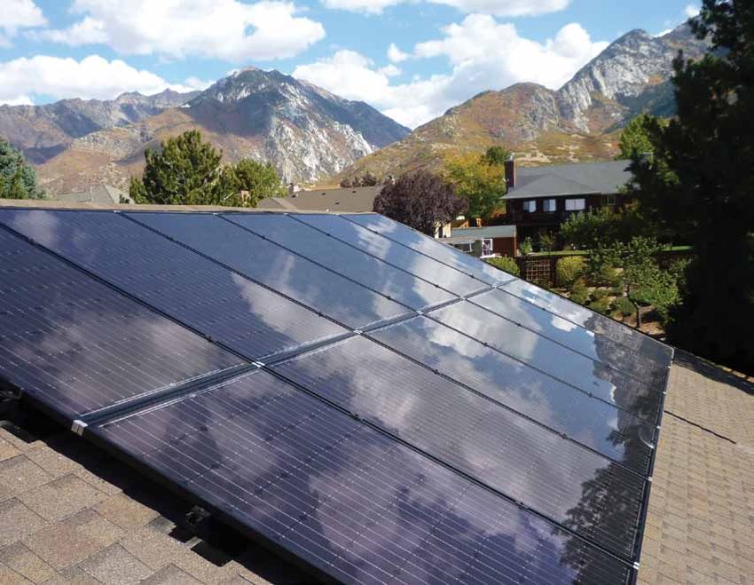
Determining wind and snow loads for solar panels                                                                 2

Figure 1. A typical rooftop solar installation.

U.S. model building codes have used ASCE 7-05 as the        (IBC) that includes references to ASCE 7-10 and, for the
basis for several years, which largely follows the design   first time, specifically mentions PV systems. There are
principles of Allowable Stress Design. Recently ASCE        several key differences between these two versions
7-10 was published and has become the basis for the         of ASCE 7 standards. This paper provides sample
2012 series of the International Codes (I-Codes). ASCE      calculations following both ASCE 7 standards that are
7-10 represents a shift in design principles toward Load    reflected in the 2012 IBC and earlier versions.
Resistance Factor Design. A few states have already
adopted the 2012 International Building Code 2012
Determining wind and snow loads for solar panels                                                               3

Below are the portions of the code that will be referenced in the sample calculations:

IBC 2012 (ASCE 7-10) Code References                      IBC 2009 (ASCE 7-05) Code References

1509.7.1 Wind resistance. Rooftop mounted pho-            1608.1 Design snow loads shall be determined
tovoltaic systems shall be designed for wind loads        in accordance with Chapter 7 of ASCE 7, but
for component and cladding in accordance with             the design roof load shall not be less than that
Chapter 16 using an effective wind area based on          determined by Section 1607.
the dimensions of a single unit frame.
                                                          1603.1.4 Wind Design Data
1603.1.4 Wind Design data. The following information
related to wind loads shall be shown, regardless of       1) Basic wind
whether wind loads govern the design of the lateral       2) Wind importance factor
force resisting system of the structure:                  3) Wind exposure
                                                          4) The applicable internal pressure coefficient
1) Ultimate design wind speed, V
                                                          5) Components and cladding
2) Risk category
3) Wind Exposure                                          1609.1.1 Wind loads on every building or structure
                                                          shall be determined in accordance with Chapter 6
4) Internal pressure coefficient
                                                          of ASCE 7.
5) Component and cladding
                                                          Table 1609.3.1, which converts from 3-second gusts
1608.1 Design snow loads shall be determined              to fastest-mile wind speeds.
in accordance with Chapter 7 of ASCE 7, but
the design roof load shall not be less than that          1609.4.1 Wind Directions and Sectors
determined by section 1607.
                                                          1) Select wind direction for wind loads to be evaluated.
1609.1.1 Determination of wind loads. Wind loads          2) Two upwind sectors extending 45 degrees from either
on every building or structure shall be determined           side of the chosen wind direction are the markers.
in accordance with Chapter 26 to 36 of ASCE 7 or          3) Use Section 1609.4.2 and Section 1609.4.3 to
provisions of the alternate all-heights method in            determine the exposure in those sectors.
section 1606.6.
                                                          4) The exposure with the highest wind loads is chosen
                                                             for that wind direction.
1609.4.1 Wind Directions and Sectors. For each
selected wind direction at which the wind loads           1609.4.2 Surface Roughness Categories
are to be evaluated, the exposure of the building
or structure shall be determined for the two upwind       1) Surface roughness B: Urban, suburban, wooded,
sectors extending 45 degrees either side of the              closely spaced obstructions.
selected wind direction. The exposures in these two       2) Surface roughness C: Open terrain with few
sectors shall be determined in accordance with               obstructions (generally less than 30 feet), flat open
Section 1609.4.2 and 1609.4.3 and the exposure               country, grasslands, water surfaces in hurricane-
resulting in the highest wind loads shall be used to         prone regions.
represent wind from that direction.                       3) Surface roughness D: Flat areas and water surfaces
                                                             outside of hurricane prone regions, smooth mud
                                                             flats, salt flats, unbroken ice.
Determining wind and snow loads for solar panels 4
In this paper, examples explain step-by-step ■ The building is not in an extreme geographic
procedures for calculating wind and snow loads location such as a narrow canyon a steep cliff.
on PV systems with the following qualifications in ■ The building has a flat or gable roof with a pitch
accordance with ASCE. less than 45 degrees or a hip roof with a pitch less
than 27 degrees.
The recommended chapter references for ASCE 7-05 are:
In case of designing more complicated projects the
■ Chapter 2 – Load Combinations
following sections are recommended:
■ Chapter 6 – Wind Load Calculations
■ Chapter 7 – Snow Load Calculations ■ ASCE 7-05: Section 6.5.13.2
■ ASCE 7-10: Section 30.8
In ASCE 7 -10, the chapters have been re-organized
and provide more detailed guidance on certain Example 1 - Residential Structure in Colorado:
topics. The recommended chapter references are:
System Details:
■ Chapter 2 – Load Combinations
■ Location: Colorado
■ Chapter 7 – Snow Load Calculations
■ Terrain: Urban, suburban, wooded, closely spaced
■ Chapters 26 – 31 Wind Load Calculations
obstructions
Example calculations: ■ Exposure: Class B
■ Building Type: Single-story residential (10- to 15-feet tall)
In the following examples, we outline how a designer
should calculate the effect of wind and snow loads ■ Mean height of roof: ~12.33 feet
on a PV module for residential and commercial ■ Building Shape: Gable roof with 30° pitch (7:12)
buildings based on few assumptions and using the ■ System: Two Rail System; attached module at four
Low-Rise Building Simplified Procedure. points along the long side between 1/8 to 1/4
points as described in the SolarWorld Sunmodule
■ ASCE 7-05: Section 6.4
User Instruction guide
■ ASCE 7-10: Section 30.5
■ Module area: 18.05 ft (Reference: Sunmodule
datasheet)
In the Simplified Method the system must have the
following qualifications (see ASCE 7.05 section 6.4.1.2 ■ Module weight: 46.7 lbs (Reference: Sunmodule
or ASCE 7-10 section 30.5.1 for further explanation): datasheet)
■ Site ground snow load (Pg): 20 psf
■ The modules shall be parallel to surface of the roof
with no more than 10 inches of space between
the roof surface and bottom of the PV module.
■ The building height must be less than 60 feet.
■ The building must be enclosed, not open or
partially enclosed structure like carport.
■ The building is regular shaped with no unusual
geometrical irregularity in spatial form, for
example a geodesic dome.Determining wind and snow loads for solar panels 5
SYMBOLS AND NOTATIONS ■ Ct = Thermal factor
■ I = Importance factor
Wind
■ Pf = Snow load on flat roof
■ I = Importance factor ■ Pg = Ground snow load
■ Kzt = Topographic factor ■ Ps = Sloped roof snow load
■ P = Design pressure to be used in determination of
Load Combination
wind loads for buildings
■ Pnet30 = Net design wind pressure for exposure B at ■ D* = Dead load
h = 30 feet and I = 1.0
■ E = Earthquake load
■ V = Basic wind speed
■ F = Load due to fluids with well-defined pressures
■ λ = Adjustment factor for building height and and maximum heights
exposure
■ H = Load due to lateral earth pressure, ground
■ Zone 1 = Interiors of the roof (Middle) water pressure or pressure of bulk materials
■ Zone 2 = Ends of the roof (Edge) ■ L = Live load
■ Zone 3 = Corners of the roof ■ Lr = Roof live load
■ R = Rain load
Snow
■ S* = Snow load
■ Ce = Exposure factor ■ T = Self-straining load
■ Cs = Slope factor ■ W* = Wind load
Hip Roof Gable Roof
Interior Zones Interior Zones Interior Zones
Roofs - Zone 1 Roofs - Zone 2 Roofs - Zone 3
* In this white paper we only use dead, snow and wind loads.Determining wind and snow loads for solar panels 6
ASCE 7-10 (IBC 2012) ASCE 7-05 (IBC 2009)
Steps in wind design: Steps in wind design:
1. Determine risk category from Table 1.5-1 1. Determine risk category from Table 1.5-1
■ Risk category type II ■ Risk category type II
2. Determine the basic wind speed, V, for applicable 2. Determine the basic wind speed, V, for
risk category (see Figure 26.5-1 A, B, C) applicable risk category (see Figure 6-1 A, B, C)
■ Wind speed in Colorado is V = 115 mph ■ Wind speed in Colorado is V = 90 mph
(excluding special wind regions) (excluding special wind regions)
3. Determine wind load parameters: 3. Determine wind load parameters:
■ Exposure category B, C or D from Section 26.7 ■ Exposure category B, C or D from Section 6.5.6.3
● Exposure B ● Exposure B
■ Topographic factor, Kzt, from Section 26.8 and ■ Topographic factor, Kzt, from Section 6.5.7.2
Figure 26.8-1
● Kzt = 1.0
● Kzt = 1.0
4. Determine wind pressure at h = 30 ft, Pnet30, from 4. Determine wind pressure at h = 30 ft, Pnet30, from
figure 30.5-1 Figure 6.3
5. Determine adjustment for building height and 5. Determine adjustment for building height and
exposure, λ, from Figure 30.5-1 exposure, λ, from Figure 6.3
■ Adjustment factor for Exposure B is λ = 1.00 ■ Adjustment factor for Exposure B is λ = 1.00
6. Determine adjusted wind pressure, Pnet, from 6. Determine adjusted wind pressure, Pnet, from
Equation 30.5-1 Equation 6-1
■ Pnet = λKzt Pnet30 ■ Pnet = λKzt Pnet30
Wind effective area is the pressure area on the Wind effective area is the pressure area on the
module that is distributed between four mounting module that is distributed between four mounting
clamps. Each mid-clamp takes one-quarter of the clamps. Each mid-clamp takes one-quarter of the
pressure and holds two modules which are equal to pressure and holds two modules which are equal to
one-half area of one module. one-half area of one module.
■ Area of module is 18.05 square feet. ■ Area of module is 18.05 square feet.
■ Effective area is ~10 square feet. ■ Effective area is ~10 square feet.
Pnet for wind speed of 115 mph and the wind Pnet for wind speed of 90 mph and the wind effective
effective area of 10 ft2: area of 10 ft2:Determining wind and snow loads for solar panels 7
ASCE 7-10 (IBC 2012) (Cont'd) ASCE 7-05 (IBC 2009) (Cont'd)
Zone 1 Zone 1
■ Downward: +21.8 psf ■ Downward: +13.3 psf
■ Upward: -23.8 psf ■ Upward: -14.6 psf
Pnet = λKzt Pnet30 Pnet = λKzt Pnet30
PDown = 1 * 1 * 21.8 = 21.8 psf PDown = 1 * 1 * 13.3 = 13.3 psf
Pup = 1 * 1 * -23.8 = -23.8 psf Pup = 1 * 1 * -14.6 = -14.6 psf
Zone 2 Zone 2
■ Downward: +21.8 psf ■ Downward: +13.3 psf
■ Upward: -27.8 psf ■ Upward: -17psf
Pnet = λKzt Pnet30 Pnet = λKzt Pnet30
PDown = 1 * 1 * 21.8 = 21.8 psf PDown = 1 * 1 * 13.3 = 13.3 psf
Pup = 1 * 1 * -27.8 = -27.8 psf Pup = 1 * 1 * -17 = -17 psf
Zone 3 Zone 3
■ Downward: +21.8 psf ■ Downward: +13.3 psf
■ Upward: -27.8 psf ■ Upward: -17psf
Pnet = λKzt Pnet30 Pnet = λKzt Pnet30
PDown = 1 * 1 * 21.8 = 21.8 psf PDown = 1 * 1 * 13.3 = 13.3 psf
Pup = 1 * 1 * -27.8 = -27.8 psf Pup = 1 * 1 * -17 = -17 psf
Steps in snow design: Steps in snow design:
1. For sloped roof snow loads Ps = Cs x Pf 1. For sloped roof snow loads Ps = Cs x Pf
2. Pf is calculated using Equation 7.3-1 2. Pf is calculated using Equation 7.3-1
■ Pf = 0.7 x Ce x Ct x Is x Pg ■ Pf = 0.7 x Ce x Ct x Is x Pg
3. When ground snow load is less than or equal to 3. When ground snow load is less than or equal to
20 psf then the minimum Pf value is I * 20 psf. (7.3.4) 20 psf then the minimum Pf value is I * 20 psf. (7.3.4)
4. Find exposure factor from Table 7-2, in category B 4. Find exposure factor from Table 7-2, in category B
and fully exposed roof and fully exposed roof
■ Ce = 0.9 ■ Ce = 0.9Determining wind and snow loads for solar panels 8
ASCE 7-10 (IBC 2012) (Cont'd) ASCE 7-05 (IBC 2009) (Cont'd)
5. Determine thermal factor using Table 7-3, for 5. Determine thermal factor using Table 7-3, for
unheated and open air structures unheated and open air structures
■ Ct = 1.2 ■ Ct = 1.2
6. Find the importance factory from Table 1.5-2 6. Find the importance factory from Table 7-4
■ Is = 1.00 (7-10) ■ Is = 1.0 (7-05)
7. Using Section 7.4 determine Cs. Using above 7. Using Section 7.4 determine Cs. Using above
values and θ = 30° values and θ = 30°
■ Cs = 0.73 ■ Cs = 0.73
Pf = 0.7 x Ce x Ct x Is x Pg Pf = 0.7 x Ce x Ct x Is x Pg
Pg ≤ 20 lbs Pg ≤ 20 lbs
Pg is the ground snow load and cannot be used Pg is the ground snow load and cannot be used
instead of the final snow load Pf for the sloped roof instead of the final snow load Pf for the sloped roof
in our load combinations' equations. We need to in our load combinations’ equations. We need to
calculate the sloped roof snow load as follows: calculate the sloped roof snow load as follows:
Pf = 0.7 * 0.9 * 1.2 * 1 * 20 = 15.12 psf or 1 * 20 Pf = 0.7 * 0.9 * 1.2 * 1 * 20 = 15.12 psf or 1 * 20
Ps = Cs x Pf Ps = Cs x Pf
Ps = 0.73 * 20 = 14.6 psf Ps = 0.73 * 20 = 14.6 psf
Load Combinations: (LRFD) Load Combinations: (ASD)
Basic combinations Section 2.3.2, according to ASCE Basic combinations Section 2.3, according to ASCE
7-10 structures, components and foundations shall 7-05 loads listed herein shall be considered to act in
be designed so that their design strength equals the following combinations; whichever produces the
or exceeds the effects of the factored loads in the most unfavorable effect in the building, foundation
following combinations: or structural member being considered. Effects of
one or more loads on acting shall be considered.
1) 1.4D 1) D + F
2) 1.2D + 1.6L + 0.5 (Lr or S or R) 2) D + H + F + L + T
3) 1.2D + 1.6 (Lr or S or R) + (L or 0.5W) 3) D + H + F + (Lr or S or R)
4) 1.2D + 1.0W + L + 0.5 (Lr or S or R) 4) D + H + F + 0.75 (L + T) + 0.75 (Lr or S or R)
5) 1.2D + 1.0E + L + 0.2S 5) D + H + F + (W or 0.7 E)
6) 0.9D + 1.0W 6) D + H + F + 0.75 (W or 0.7 E) + .75L + .75 (Lr or S or R)
7) 0.9D + 1.0E 7) 0.6D + W + H
8) 0.6D + 0.7E + HDetermining wind and snow loads for solar panels 9
ASCE 7-10 (IBC 2012) (Cont'd) ASCE 7-05 (IBC 2009) (Cont'd)
The highest values for upward and downward The highest values for upward and downward
pressures will govern the design. pressures will govern the design.
Load Case 3) Load Case 6)
1.2 * 2.59 + 1.6 (14.6) + 0.5 (21.8) = 37.4 psf 2.59 + 0.75 (14.6) + 0.75 (13.3) = 23.5 psf
Load Case 6) Load Case 7)
0.9 * 2.59 + 1.0 (-27.8) = -25.7 psf 0.6 (2.59) + 1.0 (-17.0) = -15.45 psf
The next step is to check that the module can The next step is to check that the module can
withstand the design loads for this two-rail mounting withstand the design loads for this two-rail mounting
configuration. The designer should refer to the configuration. The designer should refer to the
module installation instructions where the design module installation instructions where the design
loads for different mounting configurations are loads for different mounting configurations are
provided. provided.
Fmin, max Fmin, max
When two rails are supporting the module with top- When two rails are supporting the module with top-
down clamps, the module design capacity is: down clamps, the module design capacity is:
■ Downward: +113 psf ■ Downward: +55 psf
■ Upward: -64 psf ■ Upward: 33 psf
These values are well above the governing design These values are well above the governing design
loads of: loads of:
■ Downward: +37.4 psf ■ Downward: +23.5 psf
■ Upward: -25.7 psf ■ Upward: -15.45 psf
To distribute the combined loads on the module To distribute the combined loads on the module
that are transferring to the rails, please refer to the that are transferring to the rails, please refer to the
Mounting User Instruction guide and ASCE 7-10 Mounting User Instruction guide and ASCE 7-05
section 30.4. section 6.5.12.2.Determining wind and snow loads for solar panels 10
Example calculations ■ Exposure: Class B
■ Building Type: Two-story Commercial (25 feet
In the following example we outline how a designer
tall)
should calculate the effect of wind and snow on a
PV module for commercial buildings based on few ■ Mean height of roof: ~25.33 feet
assumptions and using Main Wind-force Resisting ■ Building Shape: Gable roof with 5° pitch (1:12)
Systems design. ■ System: Two Rail System; attached module at
four points along the long side between 1/8
■ ASCE 7-05: Section 6.5.12.4.1
to 1/4 points as described in the SolarWorld
■ ASCE 7-10: Section 30.4 Sunmodule User Instruction guide
Example 2- Commercial Structure in Colorado: ■ Module area: 18.05 ft. (Reference: Sunmodule
Datasheet)
■ Location: Colorado
■ Module weight: 46.7 lbs (Reference:
■ Terrain: Urban, suburban, wooded, closely
Sunmodule Datasheet)
spaced obstructions
■ Site ground snow load (Pg ): 20 psf
SYMBOLS AND NOTATIONS ■ Ct = Thermal factor
■ I = Importance factor
Wind
■ Pf = Snow load on flat roof
■ Cn = New pressure coefficient to be used in ■ Pg = Ground snow load
determination of wind loads ■ Ps = Sloped roof snow load
■ G = Gust effect factor
Load Combination
■ I = Importance factor
■ Kd = Wind directionality factor ■ D* = Dead load
■ Kz = Velocity pressure exposure coefficient ■ E = Earthquake load
evaluated at height z
■ F = Load due to fluids with well-defined pressures
■ Kzt = Topographic factor and maximum heights
■ P = Design pressure to be used in determination of ■ H = Load due to lateral earth pressure, ground
wind loads for buildings water pressure or pressure of bulk materials
■ qh = Velocity pressure evaluated at height z = h ■ L = Live load
■ θ = Tilt angle of the module ■ Lr = Roof live load
■ R = Rain load
Snow
■ S* = Snow load
■ Ce = Exposure factor ■ T = Self-straining load
■ Cs = Slope factor ■ W* = Wind load
* In this white paper we only use dead, snow and wind loads.Determining wind and snow loads for solar panels 11
ASCE 7-10 (IBC 2012) ASCE 7-05 (IBC 2009)
Steps in wind design: Steps in wind design:
1. Determine risk category from Table 1.5-1 1. Determine risk category from Table 1.5-1
■ Risk category type II ■ Risk category type II
2. Determine the basic wind speed, V, for applicable 2. Determine the basic wind speed, V, for applicable
risk category (see Figure 26.5-1 A, B, C) risk category (see Figure 6.1 A, B, C)
■ Wind speed in Colorado is V = 115 mph ■ Wind speed in Colorado is V = 90 mph
(excluding special wind regions) (excluding special wind regions)
3. Determine wind load parameters: 3. Determine wind load parameters:
■ Wind Directionality factor, Kd, see Section 26.6 ■ Wind Directionality factor, Kd, see Section 6.5.4.4
● Main wind-force resisting system ● Main wind-force resisting system
components and cladding, Kd = 0.85 components and cladding, Kd = 0.85
■ Exposure category B, C or D from Section 26.7 ■ Exposure category B, C or D from Section 6.5.6.3
● Exposure B ● Exposure B
■ Topographic factor, Kzt, from Section 26.8 and ■ Topographic factor, Kzt, from Section 6.5.7.2
Figure 26.8-1
● Kzt = 1.0
● Kzt = 1.0
4. Determine velocity pressure exposure coefficient, 4. Determine velocity pressure exposure coefficient,
Kz of Kh, see Table 30.3-1 Kz of Kh, see Table 6-3
● For exposure B and height of 25 ft, Kz = 0.7 ● For exposure B and height of 25 ft, Kz = 0.7
5. Determine velocity pressure, qh, Eq. 30.3-1 5. Determine velocity pressure, qh, Eq. 6-15
■ qh = 0.00256 x Kz x Kzt x Kd x V2 ■ qh = 0.00256 x Kz x Kzt x Kd x V2 x 1
6. Determine net pressure coefficient, GCp 6. Determine net pressure coefficient, GCp
■ See Fig. 30.4-2A ■ See Fig. 6-11B
■ Downward: GCp = 0.3 ■ Downward: GCp = 0.3
■ Upward: GCp = -1.0 (zone 1) ■ Upward: GCp = -1.0 (zone 1)
-1.8 (zone 2) -1.8 (zone 2)
-2.8 (zone 3) -2.8 (zone 3)Determining wind and snow loads for solar panels 12
ASCE 7-10 (IBC 2012) (Cont'd) ASCE 7-05 (IBC 2009) (Cont'd)
7. Calculate wind pressure, p, Eq. 30.8-1 7. Calculate wind pressure, p, Eq. 6-26
■ p = qh GCp ■ p = qh GCp
qh = 0.00256 x kz x kzt x kd x V2 qh = 0.00256 x kz x kzt x kd x V2
qh = 0.00256 * 0.7 * 1 * 0.85 * 1152 = 20.14 psf qh = 0.00256 * 0.7 * 1 * 0.85 *902 = 12.34 psf
pdown = 20.14 * 0.3 = 6.04 psf pd = 12.34 * 0.3 = 3.7 psf psf
pup = 20.14 * (-2.8) = 56 psf pu = 12.34 * (-2.8) = 34.6 psf
Steps in Snow design: Steps in Snow design:
1. For sloped roof snow loads Ps = Cs x Pf 1. For sloped roof snow loads Ps = Cs x Pf
2. Pf is calculated using Equation 7.3-1 2. Pf is calculated using Equation 7.3-1
■ Pf = 0.7 x Ce x Ct x Is x Pg ■ Pf = 0.7 x Ce x Ct x Is x Pg
3. When ground snow load is less than or equal 20 3. When ground snow load is less than or equal 20
psf then the minimum Pf value is I * 20 psf (7.3.4) psf then the minimum Pf value is I * 20 psf (7.3.4)
4. Find exposure factor from Table 7-2, in category B 4. Find exposure factor from Table 7-2, in category B
and fully exposed roof and fully exposed roof
■ Ce = 0.9 ■ Ce = 0.9
5. Determine Thermal factor using Table 7-3, for 5. Determine Thermal factor using Table 7-3, for
unheated and open air structures unheated and open air structures
■ Ct = 1.2 ■ Ct = 1.2
6. Find the importance factory from Table 1.5-2 6. Find the importance factory from Table 7-4
■ Is = 1.00 (7-10) ■ Is = 1.0 (7-05)
7. Using Section 7.4 determine Cs. Using above 7. Using section 7.4 determine Cs. Using above
values and θ = 5° values and θ = 5°
■ Cs =1.0 ■ Cs =1.0
Pf = 0.7 x Ce x Ct x Is x Pg Pf = 0.7 × Ce × Ct × Is × PgDetermining wind and snow loads for solar panels | 13
ASCE 7-10 (IBC 2012) (Cont'd) ASCE 7-05 (IBC 2009) (Cont'd)
Pg ≤ 20 lbs Pg ≤ 20 lbs
Pg is the ground snow load and cannot be used Pg is the ground snow load and cannot be used
instead of the final snow load for the sloped roof instead of the final snow load for the sloped roof
in our load combinations’ equations. We need to in our load combinations’ equations. We need to
calculate the sloped roof snow load as follows: calculate the sloped roof snow load as follows:
Pf = 0.7 * 0.9 * 1.2 * 1 * 20 = 15.12 psf or 1 * 20 Pf = 0.7 * 0.9 * 1.2 * 1 * 20 = 15.12 psf or 1 * 20
Ps = Cs x Pf Ps = Cs x Pf
To find out the effect of snow load perpendicular to the To find out the effect of snow load perpendicular to the
plane of module we multiply the Ps value by COS (θ). plane of module we multiply the Ps value by COS (θ).
Ps = 1 * 20 * COS (5°) = 19.9 psf Ps = 1 * 20 * COS (5°) = 19.9 psf
Load combinations: (LRFD) Load Combinations: (ASD)
Basic combinations section 2.3.2, according to ASCE Basic combinations section 2.3.2, according to ASCE
7-10 structures, components and foundations shall 7-05 loads listed herein shall be considered to act in
be designed so that their design strength equals or the following combinations; whichever produces the
exceeds the effects of the factored loads in following most unfavorable effect in the building, foundation
combinations: or structural member being considered. Effects of
one or more loads on acting shall be considered.
1) 1.4D 1) D + F
2) 1.2D + 1.6L + 0.5 (Lr or S or R) 2) D + H + F + L + T
3) 1.2D + 1.6 (Lr or S or R) + (L or 0.5W) 3) D + H + F + (Lr or S or R)
4) 1.2D + 1.0W + L + 0.5 (Lr or S or R) 4) D + H + F + 0.75 (L + T) + 0.75 (Lr or S or R)
5) 1.2D + 1.0E + L + 0.2S 5) D + H + F + (W or 0.7E)
6) 0.9D + 1.0W 6) D + H + F + 0.75 (W OR 0.7E) + .75L + .75 (Lr or S or R)
7) 0.9D + 1.0E 7) 0.6D + W + H
8) 0.6D + 0.7E + H
The highest values for upward and downward The highest values for upward and downward
pressures will govern the design. pressures will govern the design.Determining wind and snow loads for solar panels | 14
ASCE 7-10 (IBC 2012) (Cont'd) ASCE 7-05 (IBC 2009) (Cont'd)
Load Case 3) Load Case 6)
1.2 * 2.59 + 1.6 (19.9) + 0.5 (6.04) = 38 psf 2.59 + 0.75 (19.9) + 0.75 (3.7) = 20.3 psf
Load Case 6) Load Case 7)
0.9 * 2.59 + 1.0 (-56) = -53.7 psf 0.6 (2.59) + 1.0 (-34.6) = -33 psf
The next step is to check that the module can The next step is to check that the module can
withstand the design loads for this two-rail mounting withstand the design loads for this two-rail mounting
configuration. The designer should refer to the configuration. The designer should refer to the
module installation instructions where the design module installation instructions where the design
loads for different mounting configurations are loads for different mounting configurations are
provided. provided.
Fmin, max Fmin, max
For the case of two rails simply supporting the module For the case of two rails simply supporting the module
with top-down clamps, the module design capacity is: with top-down clamps, the module design capacity is:
■ Downward: +113 psf ■ Downward: +55 psf
■ Upward: -64 psf ■ Upward: -33 psf
These values are above the governing design loads These values are above the governing design loads
of: of:
■ Downward: +38 psf ■ Downward: +20.3 psf
■ Upward: -53.7 psf ■ Upward: -33 psf
To distribute the combined loads which are To distribute the combined loads which are
transferring to the rails please refer to the Mounting transferring to the rails please refer to the Mounting
User Instruction and ASCE 7-10 section 30.4. User Instruction and ASCE 7.05 section 6.5.12.2.Determining wind and snow loads for solar panels SW-02-5156US-MEC 04-2013 | 15 As this white paper illustrates, SolarWorld Sunmodules easily meet many high wind and snow load requirements within the United States and therefore are ideal for installation in most climates. The ability to meet these requirements is essential when designing solar systems that are expected to perform in various weather conditions for at least 25 years. As America’s solar leader for over 35 years, SolarWorld’s quality standards are unmatched in the industry. Unlike most other solar manufacturers in the market today, our systems have proven performance in real world conditions for over 25 years. References 1. Minimum design loads for buildings and other structures. Reston, VA: American Society of Civil Engineers/ Structural Engineering Institute, 2006. Print. 2. Minimum design loads for buildings and other structures. Reston, Va.: American Society of Civil Engineers :, 2010. Print. 3. International building code 2009. Country Club Hills, Ill.: International Code Council, 2009. Print. 4. International building code 2006. New Jersey ed. Country Club Hills, IL: The Council, 2007. Print.
ENGINEERED POWER SOLUTIONS
                                                              MATTHEW B. GILLISS, PROFESSIONAL ENGINEER

                                                                  879 SYCAMORE CANYON RD.
                                                                     PASO ROBLES, CA 93446
                                                                         (805) 423
                                                                               423-1326
                                                                                   1326

                              STRUCTURAL LETTER OF APPROVAL

Date:                  December
                        ecember 30,
                                30 2012

Project
Project:               Solar Module
                              odule Design Loads Methodology Review

EPS Job Number:        12-SWD003
                          SWD003

To:                    Amir Sheikh
                       SolarWorld Americas (SolarWorld)
                       4650 Adohr Lane                                               12/31/14
                       Camarillo, CA 93012

From:                  Matthew Gilliss
                       Engineered Power Solutions (EPS)

A
Att the request of SolarWorld, Engineered Power Solutions (EPS) has reviewed the design methmethodology
                                                                                                 odology
presented in SolarWorld
              SolarWorld’ss “White
                             White Paper” title Determining Wind and Snow
                                   Paper titled:                        S      Loads for Solar Panels
(Version 7)
          7). The paper presents the recommended
                                     recommended design methodology for determining the code
prescribed wind and snow loads for solar modules mounted on and flush to a roof surface in
                             009 (and 2006) International
accordance with either the 2009              International Building Code (IBC) - which reference
                                                                                         references the
2005 Minimum Design Loads for Buildings and Other Structures by the American Society of Civil
Engineers (ASCE 77-05), or the 2012 IBC – which
                                             whi references ASCE 7-  7-10. EPS has found that the
design methodology
        methodology and examples presented in this paper are consistent
                                                                      ent with the design inten
                                                                                          intentions
                                                                                                ions of
each said building code.

This letter is in approval of the general design methodology for flush roof mounted solar modules only
as discussed in the referenced paper.
                                 paper. It is the responsibility of the project engineer of record to addres
                                                                                                      address
the site specific loading conditions for each project. Please
                                                          lease note that the industry recommended
                                                                                       recommended design
methodology for roof mounted solar systems has continually changed over recent years as new studies
are published. Because of this, EPS recommends periodically reviewing the stated methodology to
ensure it matches with the most current
                                     rrent code requirements and industry recommendations.

P
Please
 lease feel free to contact me with any questions. Thank you.

Sincerely,

Matthew B. Gilliss, P.E., LEED AP
Engineered Power Solutions

Letter of Approval – SolarWorld Design Loads Methodology Review                                       Page 1
You can also read