Guideline for the use of wind monitors - IVRSA
←
→
Page content transcription
If your browser does not render page correctly, please read the page content below
Guideline
for the use of wind monitors

                  Effective as of November 2020
                  Publisher: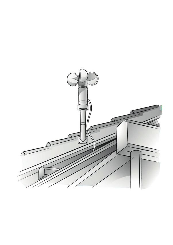
Guideline for the use of wind monitors                        Effective as of 11/2020           Page 2

Table of contents

1. Foreword                                                                                              4

2. Basic principles                                                                                     4
    2.1 Cup anemometer                                                                                  5
    2.2 Thermoelectric anemometer                                                                       6
    2.3 Vibration sensor                                                                                7

3. Guidelines, standards, insurance                                                                    8
    3.1 General information                                                                            8
    3.2 Special conditions for external Venetian blinds                                                8
    3.3 Special conditions for ZIP                                                                    10
    3.4 Insurance                                                                                     13
    3.5 Effects of winds of force of 8 to 12 on land                                                  13

4. Fluid mechanics                                                                                    14
     4.1 Characteristic of the wind (turbulence)                                                      14
     4.2 Circulation around the building                                                              15
     4.3 Wind pressure on the facade                                                                  16
     4.4 Influence of the surrounding buildings on the circulation around                             16
         the building and the facade wind pressure
     4.5 Simulation of the wind, the circulation around the building and                              17
         the facade wind pressures

5. Positioning the wind monitor on the building                                                       18
    5.1 Type of building                                                                              18
    5.2 Planning the installation situation                                                           18
    5.3 Boundary conditions relevant to planning                                                      19
    5.4 Positioning                                                                                   19
    5.5 Case studies                                                                                  21
    5.6 Installing the wind monitor                                                                   23

6. Maintenance                                                                                        24
    6.1 Maintenance/care (instructions)                                                               24
    6.2   Inspection specifications                                                                   24

                                                                         All rights, especially those relating to
                                                                         the reproduction or distribution of this
                                                                         content, both in whole or in part, are
                                                                         held exclusively by the publisher.
Guideline for the use of wind monitors                         Effective as of 11/2020             Page 3

7. Adjusting the controller                                                                              24
    7.1 Priorities in the sensor system                                                                  24
    7.2 Delay times                                                                                      24
    7.3 Requirements for building automation                                                             24
    7.4 Position of the radio wind monitor relative to the radio receiver                                24
        (actuator, drive)

8. Responsibilities and liability                                                                        25
    8.1 Commissioning (basic setting)                                                                    25
    8.2 Specifying the limit values                                                                      25

9. Conclusion                                                                                            25

                                                                            All rights, especially those relating to
                                                                            the reproduction or distribution of this
                                                                            content, both in whole or in part, are
                                                                            held exclusively by the publisher.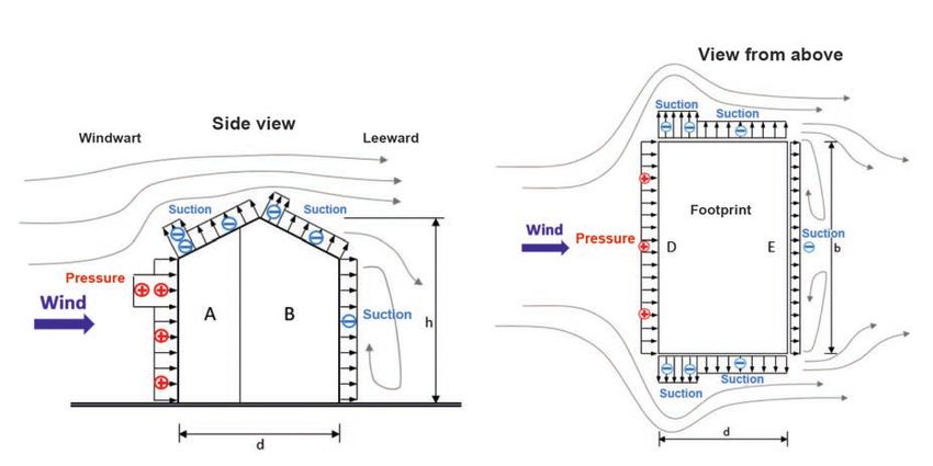
Guideline for the use of wind monitors                            Effective as of 11/2020           Page 4

1. Foreword
The control of exterior sunblind systems under the influence of wind is an important aspect
in the planning and implementation of buildings. In this context, wind monitors are import-
ant, tried-and-tested products that ensure the longest possible service life for sunblind sys-
tems in relation to the applicable wind speeds and thus also contribute to the conservation
of energy.

This guideline will provide a basis for specialist dealers and fitters as they advise the user
on product quality, technical limits and product-specific characteristics.

It will assist experts in evaluating the suitability limits of wind monitors. In addition, it
should help prevent disputes and differences of opinion.

This guideline is therefore intended for planners, manufacturers, dealers, installation com-
panies, electricians, users and operating companies.

We are especially grateful to Wacker Ingenieure GmbH, 75217
Birkenfeld, Germany www.wacker-ingenieure.de, without whose
know-how and advice this guideline could not have
been created.

2. Basic principles
Wind monitors are designed to send a signal to move the sunblind systems to their pro-
tected position when excessive levels of wind occur. To enable the wind monitor to fulfil this
task, it is necessary to choose an installation position that ensures that the wind monitor is
exposed to exactly the same wind conditions as the sunblind systems. Alternatively, knowl-
edge of the factor for converting the wind speed/wind direction on the wind monitor to the
wind speed on the sunblind is enough to control the sunblind. Wind monitors are very often
used in combination with a sun sensor. Another version is the combination of
wind monitor/sun sensor/rain sensor.

Below we describe the three most commonly used wind monitor systems:

                                          Wind monitor
                                            systems

                                          Thermoelectric
              Cup anemometer                                       Vibration sensor
                                           anemometer

            Fig.1

                                                                             All rights, especially those relating to
                                                                             the reproduction or distribution of this
                                                                             content, both in whole or in part, are
                                                                             held exclusively by the publisher.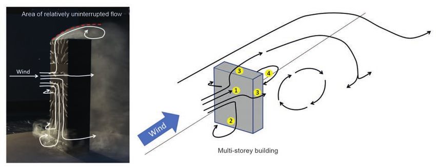
Guideline for the use of wind monitors                             Effective as of 11/2020           Page 5

     2.1 Cup anemometer

     Design
     The wind monitor is equipped with a
     cup with rotating bearings to which
     three vanes are attached. The in-
     side of the cup is fitted with mag-
     nets. A reed switch is attached in such
     a way that the contact opens brief-
     ly when the magnets are guided past.

     Functional principle
     The cup moves at different speeds, de-
     pending on the wind levels.
     The faster the cup turns, the more of-
     ten it interrupts the reed contact – this
     is referred to as the switching rate.
     This switching rate is evaluated by a
     control unit. If the switching rate ex-
     ceeds the set threshold value, a safety
     movement takes place.
                                                                                                  Fig.2

    Advantages:                          Highly robust, tried-and-tested technology

    Disadvantages:                       Updrafts and downslope winds are not detected.

    Areas of application:                Individual systems, group systems

    Installation location:               Facade, roof

    Measuring range:                     Wind force 0-12 (depending on the version)

    Versions:                            Wire-connected, radio technology

    Special versions:                    Heated (supply voltage required)

    Supply voltage:                      Without, extra-low and low voltage, solar, battery

    Signal/data transmission:            Wire-connected, radio

    Inspection:                          Annual visual inspection and function test (before
                                         the start of the season in case of seasonal use) and
                                         after special weather conditions, e.g. hail, storm

    Maintenance/care:                    Solar-powered wind monitor, annual cleaning of the
                                         solar panels, battery replacement

    Environmental influences:            The manufacturer’s specifications must be observed
                                         in this context.

                                                                              All rights, especially those relating to
                                                                              the reproduction or distribution of this
                                                                              content, both in whole or in part, are
                                                                              held exclusively by the publisher.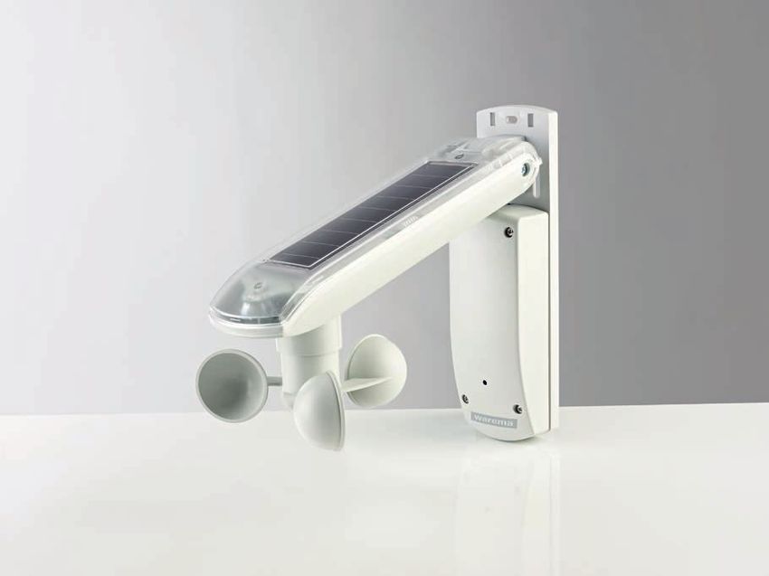
Guideline for the use of wind monitors                             Effective as of 11/2020           Page 6

     2.2 Thermoelectric anemometer

     Design
     The wind monitor is equipped with a sen-
     sor that is permanently exposed to the
     wind. The inside of the housing contains
     an electronic system that processes the
     values from the sensor. The wind moni-
     tor has no moving parts.

     Functional principle
     The sensor changes its resistance in
     dependence on wind speed; the more
     wind there is, the more the value of the
     resistance changes. The electronic sys-
     tem constantly evaluates this value and
     compares it to a pre-set threshold value.
     When this value is exceeded, a safety
     movement takes place.

                                                                                                      Fig.3

    Advantages:                          No wear of mechanical parts. Depending on the de-
                                         sign, updrafts and downslope winds can be detected.

    Disadvantages:                       Requires a voltage supply, therefore low energy
                                         requirements

    Areas of application:                Individual systems, group systems

    Installation location:               Facade, roof

    Measuring range:                     Wind force 0-12 (depending on the version)

    Supply voltage:                      Extra-low and low voltage, solar, battery

    Signal/data transmission:            Wire-connected, radio

    Inspection:                          Annual visual inspection and function test (before
                                         the start of the season in case of seasonal use) and
                                         after special weather conditions, e.g. hail, storm

    Maintenance/care:                    Annual cleaning

    Environmental influences:            The manufacturer’s specifications must be observed
                                         in this context.

                                                                              All rights, especially those relating to
                                                                              the reproduction or distribution of this
                                                                              content, both in whole or in part, are
                                                                              held exclusively by the publisher.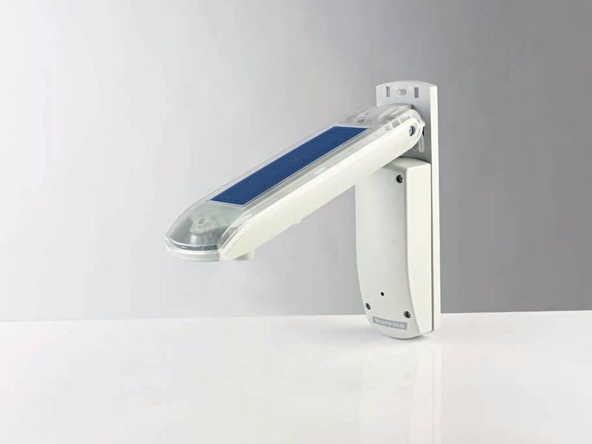
Guideline for the use of wind monitors                             Effective as of 11/2020           Page 7

     2.3 Vibration sensor

     Design
     The wind monitor is fitted with a sensor with or without additional incline detection,
     which constantly registers movements. It also contains an electronic system that pro-
     cesses the values from the sensor. The wind monitor has no moving parts.

     Functional principle
     The wind monitor is installed on the bottom rail of an extending-arm awning. If the
     bottom rail begins to vibrate or change its inclination, this is detected by the sensor
     and evaluated by the electronic system. When a set threshold value is exceeded, a
     safety movement takes place.

    Advantages:                          Direct measurement on the system

    Disadvantages:                       Only for extending-arm awnings

    Areas of application:                Single systems

    Measuring range:                     Wind force 2-8 (system-specific adjustment
                                         required)

    Versions:                            Radio technology

    Supply voltage:                      Battery

    Inspection:                          Annual visual inspection and function test (before
                                         the start of the season in case of seasonal use)

    Maintenance/care:                    Battery replacement

    Environmental influences:            The manufacturer’s specifications must be observed
                                         in this context.

                                                                              All rights, especially those relating to
                                                                              the reproduction or distribution of this
                                                                              content, both in whole or in part, are
                                                                              held exclusively by the publisher.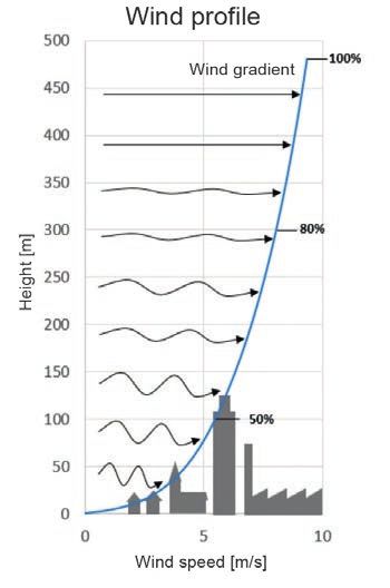
Guideline for the use of wind monitors Effective as of 11/2020 Page 8
3. Guidelines, standards, insurance
3.1 General information
The wind load on specific sections of a building or on individual sections is determined
by the pressure coefficient Cp. The Cp value is determined from the difference between
the internal pressure cpi and the external pressure cpe on the building or individual
sections. In the case of sections that are permeable by air, the internal pressure cpi
increases and thus reduces the Cp value. It should be noted that there is no preferred
or main wind direction in Germany. Buildings and their parts must thus, as a rule, be
designed to suit the most unfavourable case.
3.2 Special conditions for external Venetian blinds
In the case of external Venetian blinds, the value for Cp can fluctuate widely due to
the dynamic movements of the blinds. For this reason, defining a wind speed based on
static pressure that the external Venetian blind can withstand is not a suitable basis for
assessment.
This essential definition is provided in Appendix A of DIN EN 13659. The ground and the
distance from the facade/altitude/corner situation also affect the maximum possible wind
speed and are not considered in the standard (DIN EN 1932:2013-09 External blinds and
shutters - Resistance to wind loads - Method of testing and performance criteria), even
though these factors have a significant impact on the wind resistance of the product.
DIN EN 1932 (8.2.3 Arrangement and dimensions of the test pieces) describes the test
with the help of a defined reference value. (2,000 mm*2,500 mm) and a defined static
pressure. This means it is hardly possible to apply the tested wind class (DIN EN 13659
Table 1 — Wind resistance classes) to diverging products even according to product stan-
dard DIN EN 13659. As a result, it is necessary to draw up application recommendations
for the products (external Venetian blind) in order to enable the products to be deployed
professionally.
Wind speeds are given in m/s in the following application recommendations.
Application recommendation for flat slats, rope-guided
Flat slat, rope-guided
Width
Height 1000 1500 2000 2500 3000 3500 4000 4500 5000
1000 17 17 13 13 13 10 10 10 10
1500 17 17 13 13 13 10 10 10 10
2000 17 17 13 13 13 10 10 10 10
2500 17 13 13 13 10 10 10 10 10
3000 13 13 13 10 10 10 8 8 8
3500 13 13 10 10 10 8 8 8 8
4000 13 10 10 10 8 8 8 8 8
4500 10 10 10 8 8 8 5 5 5
5000 10 10 8 8 8 5 5 5 5
Given in m/s
Tabelle
Table 1 1
Für folgende Fälle sind die Tabellenwerte abzumindern bzw. zu erhöhen: All rights, especially those relating to
the reproduction or distribution of this
content, both in whole or in part, are
bei Fassadenabstand > 200 mm muss der Tabellenwert auf den nächstkleineren held exclusively by the publisher.
Tabellenwert abgemindert werden (z. B. von 13 auf 10),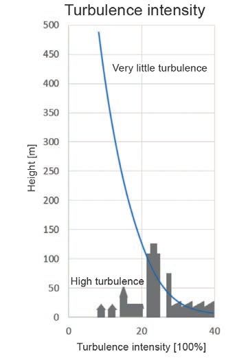
Guideline for the use of wind monitors Effective as of 11/2020 Page 9
Einsatzempfehlung Flachlamelle schienengeführt
Application recommendation for flat slats, rail-guided
Flat slat, rail-guided
Width
Height 1000 1500 2000 2500 3000 3500 4000 4500 5000
1000 17 17 13 13 13 10 10 10 10
1500 17 17 13 13 13 10 10 10 10
2000 17 17 13 13 13 10 10 10 10
2500 17 17 13 13 13 10 10 10 10
3000 17 17 13 13 13 10 10 10 8
3500 17 17 13 13 13 10 10 10 8
4000 17 13 13 13 10 10 10 8 8
4500 13 13 13 10 10 10 8 8 8
5000 10 10 10 10 10 8 8 8 8
Given in m/s
Tabelle
Table 22
Für folgende Fälle sind die Tabellenwerte abzumindern bzw. zu erhöhen:
bei Fassadenabstand > 200 mm muss der Tabellenwert auf den nächstkleineren
Tabellenwert abgemindert werden (z. B. von 13 auf 10),
bei Fassadenabstand > 300 bis 500 mm muss um 2 Stufen abgemindert werden (z.
B. von 13 auf 8), darüber hinaus kann die Tabelle nicht angewendet werden.
Application recommendation
bei Leibungsmontage for slats
kann der Tabellenwert aufflanged on both sides,
den nächstgrößeren rope-guided
Tabellenwert
erhöht werden (z. B.Slat
vonflanged
10 aufon
13) (Maximalwert
both 17 m/s) dies bis zu einer
sides, rope-guided
maximalen Breite von 3000 mm.
Width
bei geringeren Materialstärken der Lamellen als 0,4 mm muss der Tabellenwert auf
Height 1000 1500 2000 2500 3000 3500 4000 4500 5000
den nächstkleineren Tabellenwert abgemindert werden (z. B. von 13 auf 10).
1000 17 17 17 13 13 13 13 13 13
Zusätzlich sind immer
1500 die 17
Angaben
17 des17
Herstellers
13 sind zu
13 13beachten
13 (z.
13 B. zusätzliche
10
Seilführung, Anzahl
2000der FS-Halter,
17 17Wartungsintervalle).
17 13 13 13 13 13 10
2500 17 17 13 13 10 10 10 10 10
3000 13 13 13 10 10 10 8 8 8
3500 13 13 10 10 10 8 8 8 8
4000 13 10 10 10 8 8 8 8 8
4500 10 10 10 8 8 8 5 5 5
5000 10 10 8 8 8 5 5 5 5
Given in m/s
Tabelle
Table 33
Für folgende Fälle sind die Tabellenwerte abzumindern bzw. zu erhöhen:
bei Fassadenabstand > 200 mm muss der Tabellenwert auf den nächstkleineren
Tabellenwert abgemindert werden (z. B. von 13 auf 10),
bei Fassadenabstand > 300 bis 500 mm muss um 2 Stufen abgemindert werden (z.
B. von 13 auf 8), darüber hinaus kann die Tabelle nicht angewendet werden.
bei Leibungsmontage kann der Tabellenwert auf den nächstgrößeren Tabellenwert
All rights, especially those relating to
the reproduction or distribution of this
erhöht werden (z. B. von 10 auf 13) (Maximalwert 17 m/s) dies bis zu einer
content, both in whole or in part, are
held exclusively by the publisher.
maximalen Breite von 3000 mm. 5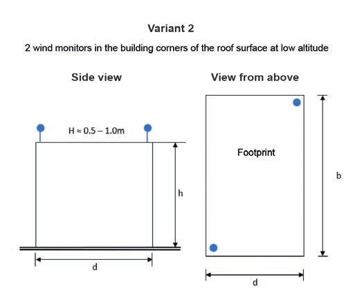
Guideline for the use of wind monitors                          Effective as of 11/2020           Page 10

    Application recommendation for slats flanged on both sides, rail-guided

                      Slat flanged on both sides, rail-guided
               Width
      Height    1000 1500 2000 2500 3000 3500 4000 4500 5000
       1000     17    17   17    17    17 17   17   17   17
       1500     17    17   17    17    17 13   13   13   13
       2000     17    17   17    17    17 13   13   13   13
       2500     17    17   17    17    17 13   13   13   13
       3000     17    17   17    17    17 13   13   13   13
       3500     17    17   17    13    13 13   13   13   10
       4000     17    17   17    13    13 13   13   10   10
       4500     17    17   17    13    13 13   10   10   10
       5000     13    13   13    13    13 10   10   10   10
                             Given in m/s
                                         Table 4

    3.3 Special conditions for awnings with fabric guided in side rails (ZIP)
    The wind classes as per DIN EN 13561 do not allow conclusions to be drawn on the
    suitability (retracting/extending, interim positions) under an actual wind load. There-
    fore the manufacturer must define the maximum speed above which the awning must
    be retracted, with reference to the reduction ratios shown in the table. This wind
    speed must be specified in the technical documentation (e.g. operating manual). The
    conditions that must be met in order to fulfil the performance requirement are based
    on static loads and do not consider the dynamic effects of repeatedly applied loads
    (turbulences) that the fabric and frame are exposed to during actual use. It is there-
    fore not possible to consult the static pressure in order to determine how the awnings
    should be anchored to the building. The ground and the distance from the facade/alti-
    tude/corner situation also affect the maximum possible wind speed and are not consid-
    ered in the standard (DIN EN 1932:2013-09 External blinds and shutters - Resistance
    to wind loads - Method of testing and performance criteria), even though these factors
    have a significant impact on the wind resistance of the product.

                                                                           All rights, especially those relating to
                                                                           the reproduction or distribution of this
                                                                           content, both in whole or in part, are
                                                                           held exclusively by the publisher.

                                                                                                   7
Guideline for the use of wind monitors Effective as of 11/2020 Page 11
Awnings with fabric guided in side rails
Width
Height 1000 1500 2000 2500 3000 3500 4000 4500 5000 5500 6000
1000 24 24 24 24 21 21 21 21 21 17 17
1500 24 24 24 21 21 17 17 17 17 17 17
2000 24 24 21 21 17 17 13 13 13 13 13
2500 24 21 21 17 17 13 13 13 13 13 13
3000 24 21 17 17 13 13 13 13 13 13 10
3500 21 17 17 13 13 13 13 13 10 10 10
4000 21 17 13 13 13 13 13 10 10 10 10
4500 21 17 13 13 13 13 10 10 10 10 10
5000 21 17 13 13 13 10 10 10 10 10 10
5500 21 17 13 13 13 10 10 10 10 10 10
6000 21 17 13 13 10 10 10 10 10 10 10
Given in m/s
Maximum speed for suitability
Table 5
Levels
24 21 17 13 10 7 4
Table 5 is only valid for a fabric distance < 100 mm from the glass surface.
The table values can be increased in the following cases:
Fig.4
• I n case of standard installation, the table value can be increased to the next higher
table value (e.g. from 10 to 13; maximum value 24 m/s), up to a maximum width
of 3,000 mm and a maximum altitude of 3,000 mm.
All rights, especially those relating to
the reproduction or distribution of this
content, both in whole or in part, are
held exclusively by the publisher.Guideline for the use of wind monitors Effective as of 11/2020 Page 12
In the following
Für folgende cases, theTabellenwerte
Fälle müssen table values must be
abgemindert reduced:
werden:
Fig.5
beim Behangabstand > 100 mm ≤ 200 mm zur Glasfläche muss der Tabellenwert
um 2 Stufen abgemindert werden (z. B. von 24 m/s auf 17 m/s),
• F
or a blind distance > 100 mm ≤ 200 mm from the glass surface, the table value
beim Behangabstand > 200 mm ≤ 300 mm zur Glasfläche muss der Tabellenwert
must be reduced by 2 levels (e.g. from 24 m/s to 17 m/s).
um 3 Stufen abgemindert werden (z. B. von 24 m/s auf 13 m/s),
Bei größeren Abständen sowie bei freistehenden Anlagen ist die Tabelle nicht
anzuwenden.
• F
or a blind distance > 200 mm ≤ 300 mm from the glass surface, the table value
mustZusätzlich sind immer
be reduced by die Angaben(e.g.
3 levels des Herstellers
from 24zum/s
beachten
to 13(z. m/s).
B. Anzahl der FS-Halter,
Kastenbefestigung, Führungschienenbefestigung, fachgerechte Montage unter Beachtung der
Toleranzen). Abweichungen sind gegebenenfalls aufgrund der Einbausituation nach
Rücksprache mit dem Hersteller möglich.
The table must not be applied if distances are larger or for free-standing sys-
tems.
In addition, the manufacturer’s specifications must always be observed (e.g. number
of guide rail holders, case mounting, guide rail mounting, professional installation with
consideration of the tolerances). Deviations due to the installation situation may be
possible after consultation with the manufacturer.
All rights, especially those relating to
the reproduction or distribution of this
content, both in whole or in part, are
held exclusively by the publisher.Guideline for the use of wind monitors Effective as of 11/2020 Page 13
3.4 Insurance
The limit above which the insurer can pay for the storm damage lies at wind force 8.
On the one hand, insurers base their claim adjustment on the information and obser-
vations provided by the Deutscher Wetterdienst (German Weather Service), and on
the other, the typical storm damage in the neighbourhood is used to evaluate the gale
force.
3.5 Effects of winds of force of 8 to 12 on land
Wind force Designation Wind speed Effects on land
8 Gale; fresh 62-74 km/h • Large trees move.
gale • Window shutters are opened.
• Branches break off trees.
• Pedestrians are severely impeded.
9 Strong/se- 75-88 km/h • Limbs break off trees.
vere gale • Minor damage to houses is possible.
• Roofing tiles and chimney covers are lifted.
• Garden furniture is thrown over and blown away.
• Pedestrians are considerably impeded.
10 Storm, whole 89-102 km/h • Trees are knocked over and uprooted.
gale • Major damage to houses
11 Violent storm 103-117 km/h • Violent gusts
• Trees are knocked over and uprooted over large
areas
• Severe storm damage to houses
• Unroofed houses
• Cars are thrown from their lanes.
• It is no longer possible to walk.
12 Hurricane from 118 km/h • Very severe and wide-spread devastation of
force woods and buildings
Table 6 (source: Deutscher Wetterdienst)
All rights, especially those relating to
the reproduction or distribution of this
content, both in whole or in part, are
held exclusively by the publisher.Guideline for the use of wind monitors Effective as of 11/2020 Page 14
4. Fluid mechanics
4.1 Characteristic of the wind (turbulence)
In meteorology, the term wind refers to air movements that are mainly the result of
spatial pressure differences. In the area close to the ground, the air molecules stream
from high pressure areas to low pressure areas. The wind flow is not uniform here, but
rather depends on the levels of various characteristics. Fig. 6 shows a typical qualita-
tive altitude-dependent progression of the wind speed of an atmospheric boundary lay-
er flow (atmospheric boundary layer flow = wind flow in the area close to the ground
up to an altitude of approx. 300 m to 400 m). In addition, the turbulence intensity (as
a measure of turbulence) of the wind above the altitude is applied on the right.
Fig. 6 shows that the wind speed increases as the altitude increases, and that simul-
taneously the turbulence intensity of the wind decreases as the altitude increases. The
wind flow in the area close to the ground is characterised by strong turbulence, which
means strong speed fluctuations. As the altitude increases, the wind flow becomes
more uniform and the wind speed increases.
➜ Average wind speed increases as ➜ Turbulence intensity decreases as the alti-
the altitude increases tude increases
➜ Wind speed increases quickly in the ➜ The area close to the ground has strong
lower altitude range turbulences
Fig. 6: Qualitative altitude-dependent development of the average wind speed (left) and turbu-
lence intensity (right) of an atmospheric boundary layer flow
All rights, especially those relating to
the reproduction or distribution of this
content, both in whole or in part, are
held exclusively by the publisher.Guideline for the use of wind monitors Effective as of 11/2020 Page 15
4.2 Circulation around the building
Buildings represent an obstacle to free and unimpeded wind flow. When wind strikes a
building, it is displaced, deflected, accelerated or slowed by that building. As a result,
various circulation effects result on the building itself and in the vicinity of the building.
These can be made visible in a wind tunnel by means of smoke tests and are outlined
in Fig. 6.1. The figures demonstrate the following effects:
1) Stagnation area of the wind flow (stagnation point): The flow strikes the
building’s facade frontally (at more or less a right angle) and is slowed heavily
in the process. The maximum wind pressure and minimum wind speed on the
facade occur at around 80% of the building’s height (this applies to higher build-
ings against which the wind can blow without interruption).
2) D
ownslope winds: The flow is directed downwards below the stagnation point.
3) Flow accelerations: Especially on the corners of buildings and edges of roofs.
Strong wind suction and high wind speed. Very high turbulent pressure and
speed fluctuations.
4) T
urbulences and backflows: in the downwind area of the building.
Note: The circulation effects shown in Fig. 6.1 are typical for a free-standing building.
Surrounding buildings can cause the illustrated flow effects to overlap with other flow
effects. These are discussed in chapter 6.3.
© Wacker Ingenieure – Wind Engineering
Fig. 6.1: V
isualisation of the circulation around a free-standing building (left: smoke test in a
wind tunnel; right: sketch of circulation)
All rights, especially those relating to
the reproduction or distribution of this
content, both in whole or in part, are
held exclusively by the publisher.Guideline for the use of wind monitors Effective as of 11/2020 Page 16
4.3 Wind pressure on the facade
The described circulation effects result in different local flow speeds and flow direc-
tions on the circulated building. Depending on the incoming flow, different areas of the
facade are subject to different levels of pressure (+) or suction (-). High suction levels
must be expected in particular at the edges. See also Fig. 6.2.
Fig. 6.2: S
implified illustration of circulation around a free-standing building as viewed from the
side (left) and from the footprint (right) with pressure and suction areas on the roof
and facade surfaces
4.4 Influence of the surrounding buildings on the circulation around the build-
ing and the facade wind pressure
Surrounding buildings and dense building development have an additional effect on the
circulation around a building and can make it extremely complex and difficult to pre-
dict. Fig. 6.3 shows examples of three typical effects caused by surrounding buildings:
1) Jet effect (examples 1 and 4): Wind flow is channelled by impermeable neigh-
bouring buildings. Significant flow acceleration in the lanes between the buildings.
Example 1: Building size W x L x H = 15 m x 15 m x 50 m, building distance 20 m,
speed increase 20% (rough reference value)
Example 4: Building size of W x L x H = 15 m x 50 m x 50 m, building distance 20
m, speed increase near the facade up to 60% (rough reference value)
2) Flow deflections (example 2): Wind flow is deflected by a building situated in
front. Increased wind load on the rear building and local change of the flow direc-
tion.
3) Higher neighbouring buildings (example 3): High-energy wind from higher
layers is “captured” by the building and deflected downwards. Increased wind load
on the lower building (section).
All rights, especially those relating to
the reproduction or distribution of this
content, both in whole or in part, are
held exclusively by the publisher.Guideline for the use of wind monitors Effective as of 11/2020 Page 17
+ 20%
1) Jet effect 2) Flow deflections
!
HL JK
HLJK !
HLJK ! HLJK !
3) Higher neighbouring buildings 4) Jet effect and flow deflections
Fig. 6.3: S
implified illustration of the circulation around a building, including surrounding build-
ings
4.5 Simulation of the wind, the circulation around the building and the facade
wind pressures
The circulation around buildings is (even with seemingly simple cubages) often highly
complex and can only be predicted to a limited extent without further examination.
In the best case, it can be estimated approximately. One way to record the circulation
around the building more precisely is to conduct computer-aided simulations of wind
flow or (even better) wind tunnel tests. In the case of complex questions, wind tunnel
tests are often the only reliable procedure for reproducing the circulation as precisely
and realistically as possible and determining facade wind pressures.
One of the major advantages that wind tunnel tests have over stationary numerical
flow calculations (computational fluid dynamics, CFD) is that the wind tunnel test also
allows wind speed fluctuations (turbulences) on the facade to be considered. This con-
siderably improves the quality of results, as temporary turbulences can be decisively
significant to the sunblind fabrics in regard to wind damage.
To illustrate this, Fig. 6.4 shows a typical wind speed signal on a facade. It is clear that
the wind speed is not a steady parameter. The wind speed close to the facade fluctu-
ates around an average value with clearly recognisable wind peaks (gusts).
All rights, especially those relating to
the reproduction or distribution of this
content, both in whole or in part, are
held exclusively by the publisher.Guideline for the use of wind monitors Effective as of 11/2020 Page 18
Wind speed time sequence on the facade
25
20
Wind speed u [m/s]
15
Time sequence
Average value
10
Gust
5
0
0 100 200 300 300 500 600 700 800 900 1000
Time [s]
Fig. 6.4: Illustration of example measurement signal for wind speed on the building facade
5. Positioning the wind monitor on the building
5.1 Type of building
Building regulation law, the design of a building and the use of a building as a residen-
tial or non-residential building do not yield any requirements for the installation of wind
monitoring systems in combination with products that are subject to DIN EN 13561
and DIN EN 13659.
On the manufacturer side, wind resistance is declared as an essential performance
characteristic for the above products in the context of CE marking.
A determination according to the intended purpose results from this. Intended use is
the duty of the specialist company performing the installation.
The professional operation of the above products is subject to the user’s or operating
company’s own responsibility.
5.2 Planning the installation situation
It must be ensured that the wind resistance declared by the manufacturer for a prod-
uct, and/or the specified maximum permitted wind speed, is not exceeded for the
blinds and shutters installed on an object. To this end, the wind speeds and/or facade
wind pressures that the building is actually exposed to must be recorded correctly. In
general the manufacturer’s specifications and recommendations must be taken into
account.
All rights, especially those relating to
the reproduction or distribution of this
content, both in whole or in part, are
held exclusively by the publisher.Guideline for the use of wind monitors Effective as of 11/2020 Page 19
5.3 Boundary conditions relevant to planning
During the planning of the wind monitoring system, and especially of the position of
the wind monitor, the actual construction situation must be considered. On the building
itself, various aerodynamic conditions occur in dependence on the following:
• Theterrain and/or geographic features (e.g. location on a hillside, the open sea)
• The surrounding buildings (e.g. solitary or dense building coverage)
• The type of building
• The building’s dimensions (height, width, length)
• Orientation in relation to the wind (downwind and upwind areas of the facade)
(see chapter 4).
This results in facades and facade areas being exposed to a corresponding load.
5.4 Positioning
A wind monitor must be positioned in such a way that the wind speed and direction
can be recorded unambiguously. As soon as the limit speed is reached, the sunblind in
the relevant facade zone is retracted. A facade zone is marked by the fact that similar
wind conditions prevail there. These facade zones are the basis for the control concepts
described below and must be determined in advance.
In general, two control concepts for the wind monitoring of the sunblind are common:
Local control: One or, if applicable, several wind monitors are installed on the facade
in each defined facade zone. As soon as the limit speed on the wind monitor is reached
or exceeded, the sunblind in the relevant facade zone is retracted.
Central control: The wind speeds and wind directions are recorded only by one, or
possibly several, wind monitors on the roof area (no wind monitor on the facade).
Based on the measurements of the central wind monitor on the roof, so-called transfer
factors are used to calculate the wind speed in the different facade zones in depen-
dence on the wind direction. As soon as the calculated speed reaches or exceeds the
limit value, the sunblind in the relevant facade zone is retracted. The transfer factors,
which are summarised in a transfer matrix, thus replace the local wind monitors on the
facade surfaces. This control variant can only be implemented by means of wind tun-
nel tests. For both control concepts, the best possible definitions of facade zones and
positioning of wind monitors can be defined on the basis of (wind tunnel) tests for the
location-specific wind conditions.
All rights, especially those relating to
the reproduction or distribution of this
content, both in whole or in part, are
held exclusively by the publisher.Guideline for the use of wind monitors Effective as of 11/2020 Page 20
Note: In addition, the wind-related theoretical outage times of the sunblind can be
determined in order to provide greater planning reliability in advance regarding which
sunblind product should be chosen with reference to wind stability.
A sunblind product with a higher wind resistance class results in fewer outage times.
In order to specifically identify the problems when positioning a roof wind monitor, Fig.
6.5 once more illustrates the flow over a building.
It shows the role that the distance between the building’s edge and the height play
when choosing the location of the roof wind monitor. The aim should always be to po-
sition the wind monitor in such a way that the measuring sensor/wind sensor is in the
free uninterrupted wind flow as far as possible.
© Wacker Ingenieure – Wind Engineering
Fig. 6.5: V
isualisation of the flow over a building in a wind tunnel with the required
measuring height of a roof wind monitor
In general, the following points must be observed above all for the positioning of all
wind monitors:
• Possibility of free flow and consideration of wind shielding due to physical struc-
tures on the building itself or due to objects in the surrounding area.
• The greatest speeds and turbulences occur on the corners of buildings and the
edges of roofs.
• When the position is chosen, seasonal special features (e.g. leaves, frost, snow
levels) should be considered.
The manufacturer’s recommendations for positioning the wind monitors must be taken
into account.
All rights, especially those relating to
the reproduction or distribution of this
content, both in whole or in part, are
held exclusively by the publisher.Guideline for the use of wind monitors Effective as of 11/2020 Page 21
5.5 Case studies
Several case studies are collected below. Examples 1 to 4 represent standard cases,
for which no project-specific tests are usually conducted in regard to the optimal wind
monitor position. The wind monitor positions shown are provided only for orientation.
Example 5 shows a larger, geometrically complex building closely surrounded by oth-
er buildings. In this case, project-specific flow simulations were conducted in the wind
tunnel in order to optimise the wind monitors (quantity and position).
In case of uncertainty in any individual case, the expertise of wind specialists must be
obtained.
Example 1: free-standing single-family house with pitched roof
H ≈ 0.8 m
Example 2: free-standing single-family house with flat roof
All rights, especially those relating to
the reproduction or distribution of this
content, both in whole or in part, are
held exclusively by the publisher.Guideline for the use of wind monitors Effective as of 11/2020 Page 22
Example 3: free-standing simple building; sunblind on only 1 facade
View from above
Control via roof wind monitors as Side view
shown in examples 1 and 2 is also
Sunblind Facade wind monitor (one or,
sensible here. if necessary, several per facade)
Important: The wind must be
able to flow freely onto the wind
monitors.
Alternatively (e.g. if the sunblind
is fitted later), wind monitors can
also be attached directly to the
facade.
Example 4: free-standing simple building; extending-arm awning
Control via roof wind monitors as shown in examples 1 and 2 is also sensible here.
Note: Wind monitors attached to directly to the facade are not recommended.
Due to the complex inconsistent flow conditions, it may be advisable
to use vibration sensors. (see chapter 2.3)
The vibration sensor should be
positioned in a place where it can
record vibrations sufficiently.
All rights, especially those relating to
the reproduction or distribution of this
content, both in whole or in part, are
held exclusively by the publisher.Guideline for the use of wind monitors Effective as of 11/2020 Page 23
Example 5: Building complex in an inner-city location
© Wacker Ingenieure – Wind Engineering © Wacker Ingenieure – Wind Engineering
• Building complex in an inner-city location with neighbouring buildings that are
equally high or higher
• Central control via roof wind monitors was not possible, as no uninterrupted
signal on the roof wind monitor was possible due to the influences from the sur-
rounding area
• Solution: local control with multiple facade wind monitors
Note: This construction project involved 16 facade wind monitors in total, which
separately control the facade areas (blue markings in the model indicate the measuring
positions during wind tunnel tests).
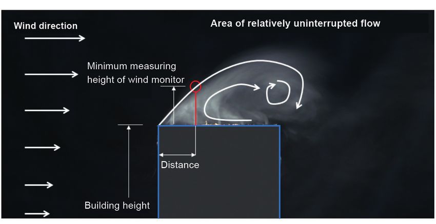
5.6 Installing the wind monitor
Depending on the installation location and installation ground, suitable aids may be
required (e.g. angle, mast, fastening material or similar).
The manufacturer’s recommendations for installing the wind monitors must be taken
into account.
All rights, especially those relating to
the reproduction or distribution of this
content, both in whole or in part, are
held exclusively by the publisher.Guideline for the use of wind monitors Effective as of 11/2020 Page 24
6. Maintenance
6.1 Maintenance/care (instructions)
The sensors must always be kept clean and free from leaves, snow or similar, and
should be tested for flawless function in the course of maintenance.
6.2 Test specifications
A battery-powered leaf blower can be used to test whether the wind monitor is func-
tioning.
Safety instruction: A firm seat (securing the person conducting the test) must be en-
sured.
In addition, a minimum distance of 1 metre from the wind monitor is recommended.
7. Adjusting the controller
7.1 Priorities in the sensor system
Wind monitors always have priority over other sensor systems, e.g. for sun and rain,
as well as over manual operation.
7.2 Delay times
A safety movement (retraction) takes place immediately after triggering. In order to
prevent repeated wind-related safety movements at too-short intervals, the extension
is delayed. The intervals typically last between 15 and 30 minutes.
7.3 Requirements for building automation
The control system should be able to manage multiple facade areas with different wind
conditions and thus different threshold values.
Note: The wind warning functions always has priority in regard to the sunblind sys-
tems.
7.4 Position of the radio wind monitor relative to the radio receiver (actuator,
drive)
Top priority: Determine exposed position of wind monitor in relation to system.
Second priority: Check radio signal to radio receiver and amplify if necessary.
It must be ensured that communications between the sensor and the centre or product
are always ensured.
All rights, especially those relating to
the reproduction or distribution of this
content, both in whole or in part, are
held exclusively by the publisher.Guideline for the use of wind monitors Effective as of 11/2020 Page 25
8. Responsibilities
8.1 Commissioning (basic setting)
Wind monitors must have an ex-works basic setting that is defined by the manu-
facturer and described in the installation instructions.
Note: The person conducting the commissioning must perform adaptations to the
wind speed suitable for the building and product.
8.2 Specifying limit values
The permitted limit value must be determined by the planner/specialist partner for the
installation height and installation situation. It is recommended that the devices regis-
ter and/or save the wind peaks so that the data can be read out in the event of com-
plaints.
Note: T
he Deutscher Wetterdienst provides precise information (https://www.dwd.de/)
9. Conclusion
Fundamentally, it should be noted that the relevant wind load on buildings must be exam-
ined on an individual basis. Corrections are required, for example, due to different condi-
tions and/or the respective location of the property.
It must be ensured that the wind monitor
• is installed in the place under wind load if possible
• is completely free and not in the wind shadow if possible
• is installed at least 0.5 to 1 m from the upper edge of the pitch roof.
Country-specific requirements must be observed!
Important: The wind must be able to flow freely onto the wind monitor.
The wind monitor must be positioned in such a way that the measuring sensor/wind sensor
is in the free uninterrupted wind flow.
Note: For more details, see the case studies under 5.5.
All rights, especially those relating to
the reproduction or distribution of this
content, both in whole or in part, are
held exclusively by the publisher.For your notes Effective as of 11/2020 Page 26
All rights, especially those relating to
the reproduction or distribution of this
content, both in whole or in part, are
held exclusively by the publisher.For your notes Effective as of 11/2020 Page 27
All rights, especially those relating to
the reproduction or distribution of this
content, both in whole or in part, are
held exclusively by the publisher.The following guidelines and recommendations are available from IVRSA e.V.:
– Guideline on Safety Instructions in Installation and Operating Instructions for Awnings
– Guideline on Technical Consultation, Sales and Installation of Extending-Arm Awnings
– Guideline on Cleaning and Care of Awning Cloth
– Association Recommendation for Use of Radio Technology in Building Automation
– Guideline for evaluating product characteristics of external Venetian blinds
– Guideline for the Evaluation of Product Characteristics of Awnings
– Instructional Content, Certificate, Order and Verification for Electrical Specialists for Specified
Duties in the Field of Skilled Shutter and Sun Protection Work
– Association Recommendation for Load Assumptions Pertaining to Wind / Suction Forces that
Must be Taken into Consideration for Manufacturing
– Sun protection along emergency evacuation routes
– Association Recommendation for Measuring Windows with Attached Shutter Boxes
– Guideline on product characteristics for insect protection
– Guideline on the maintenance of shutters and sunblind products
In collaboration with:
Bundesverband Bundesverband Wacker Ingenieure –
Rollladen + Sonnenschutz e.V. Sonnenschutztechnik Österreich e.V. Wind Engineering
Hopmannstraße 2 Canisiusweg 121, A-6020 Innsbruck Gewerbestraße 2, 75217 Birkenfeld
53177 Bonn, Germany Austria Germany
© Copyright IVRSA e.V.
is held solely by:
c/o ITRS e.V.
Heinrichstr. 79 • D-36037 Fulda, Germany
Phone: 0661 901960-11
Email: info@itrs-ev.com
Homepage: www.ivrsa.deYou can also read