TORRENT HARD SURFACE CLEANER - 120V
←
→
Page content transcription
If your browser does not render page correctly, please read the page content below
TORRENT                                            ®

                  HARD SURFACE CLEANER
                                                      120V

                                                           INFORMATION
                                                                 &
                                                             OPERATING
                                                           INSTRUCTIONS

                CAUTION: DO NOT OPERATE MACHINE UNTIL YOU HAVE READ
                      ALL SECTIONS OF THIS INSTRUCTION MANUAL

                      IMPROPER USE OF THE MACHINE WILL VOID THE WARRANTY
           1. DANGER: High pressure may cause sever injury. Always wear safety glasses.
              NEVER direct the spray towards yourself, other people, or pets.
           2. Never allow the spray to remain fixed in one spot.
           3. Before each use, remove the spray tool from the hose, and check to make sure the
              spray nozzle is securely tightened in the tool. A loose nozzle could fly off during use.
           4. If a leak occurs at the hose, IMMEDIATELY turn the machine off. Replace the hose before
              restarting.
           5. Always use a defoamer to prevent vacuum motor damage when foaming occurs.
           6. Keep the machine from rain in snow, extremes in temperatures, and store it in a heated
              location. Use the machine indoors. Do not use outdoors.
56041838

           7. NEVER adjust the pump above 1200 psi.
                                                                                                         5-2010
IMPORTANT SAFETY INSTRUCTIONS
This machine is only suitable for commercial use, for example in hotels, schools,
hospitals, factories, shops, and offices other than normal residential housekeeping
purposes.
When using any electrical appliance, basic precautions should always be followed,
including the following:
NOTE: Read all instructions before using this machine.
WARNING!
To reduce the risk of fire, electric shock, or injury:
• Never adjust the pump pressure above 1200 psi.
• Do not leave the machine unattended when it is plugged in. Unplug the unit from the outlet
when not in use and before servicing.
• To avoid electric shock, do not expose to rain or snow. Store, and use, indoors.
• Do not allow to be used as a toy. Close attention is necessary when used near children.
• Use only as described in this manual. Use only the manufacturer’s recommended
attachments.
• Do not use with damaged cord or plug. If the machine is not working as it should, has been
dropped, damaged, left outdoors or dropped into water, return it to a service center.
• Do not pull by the cord, use the cord as a handle, close a door on the cord, or pull the cord
around sharp edges or corners. Do not run the machine over the cord. Keep the cord away
from heated surfaces. To unplug, grasp the plug, not the cord.
• Do not handle the plug, the cord or the machine with wet hands.
• Extension cords must be 12/3 and no longer than 50 feet. Replace the cord or unplug
immediately if the ground prong becomes damaged.
• Do not put any object into openings. Do not use with any opening blocked; keep free of
dust, lint, hair, and anything that may reduce air flow.
• Keep loose clothing, hair, fingers, and all parts of body away from openings and moving
parts.
• Do not pick up anything that is burning or smoking, such as cigarettes, matches, or hot
ashes, or any health endangering dusts. Do not use to pick up flammable or combustible
liquids such as gasoline or use in areas where they may be present.
• Turn off all controls before unplugging.
• Connect to a properly grounded outlet only.
• Liquid ejected at the spray nozzle could be dangerous as a result of its temperature,
pressure, and/or chemical content.INSPECTION:
Carefully unpack and inspect your TORRENT for shipping damage. Each machine is tested and inspected
before shipping. Any shipping damage is the responsibility of the carrier. You should notify the carrier
immediately if you notice damage to the box or to the machine or parts.
CLEANING SOLUTIONS:
Select a proper pre-spray for the surface to be cleaned, and apply the pre-spray. Use a neutral pH rinse
or detergent (5 to 10 pH) in the Torrent to prevent premature wear of the pump, seals, and other
components. Damage caused by the use of improper or strong chemicals is not covered by warranty.
Powders are not recommended.
MAINTENANCE:
For optimum performance, flush the machine with clear water at the end of each working day. Once a
month, minimum, run a flushing compound through the machine to break up any mineral or chemical
build-up that may have formed.
Your Torrent is supplied with an HT Technology Triplex Plunger Pump, specifically designed to handle
rigorous duty cycles and high temperatures. Seal life is expected to be 3000 hours.
This pump has an oil-bath crankcase, and a sight gauge is provided so you can view the oil level through
a small opening in the front of the base compartment, directly below the ammeter gauge. The proper fill
level is shown by a red dot. Oil changes are recommended every 300 hours, and on new machines an
initial oil change is recommended at fifty hours. Use SAE-15W-40 oil. See PUMP MAINTAINENCE for
more information. Note that the hoses above the fill port are on quick disconnects to simplify service.
Vacuum motors typically require brush replacement between 500 - 1000 hours.
Clean the body with an all purpose detergent, and protect it with an automobile interior polish. Lubricate
the wheels, castors, and quick disconnects with an all-purpose silicone spray.
Record the serial number and model of your new extractor here:
(and be sure to register your purchase to active your warranty -- go to www.usproducts.com)
Serial Number: __________________ Model: TORRENT-120
Purchase Date:_____________
Write the name and phone number of your distributor:
____________________________________________________________________
____________________________________________________________________
KEEP THESE INSTRUCTIONSSWITCH PLATE CONTROLS: (refer to Figure 1) I I I
Vacuum I Switch (1): Turns on/off vacuum motor I.
1 2 3
O O O
Vacuum II Switch (2): Turns on/off vacuum motor II.
I
Dump Pump Switch (3): Turns on/off dump pump. Float switch on
recovery tank automatically turns the pump on when the HIGH
PRESSURE
4
solution level in the tank reaches a pre-set level AND the switch is on the ON O
position. U.S. PRODUCTS
High Pressure Pump Switch (4): Turns on/off the high
pressure (400-1200 psi) pump. 5
Dual Cord Sensor Light (5): The green light will turn on only when the
two power cords are plugged into separate circuits.
Hour Meter (6): Keeps track of the overall time the pump has been in use.
6
FIGURE 1
FRONT PANEL: (refer to Figure 2)
Pressure Gauge: Measures outlet pressure of high pressure pump in pounds per square inch (psi).
Ammeter: Allows precise adjustment of the pump outlet pressure without overloading the pump mo-
tor. Proper adjustment for maximum pressure is at the break line between green and yellow.
NOTE: Since voltage can vary from one power outlet to another, setting the pressure adjustment based
on amp draw will extend the life of the motor by keeping the current within the correct range.
Pressure Adjustment Knob – Adjusts outlet pressure between 400 – 1200 psi. Note: you must
trigger the tool and spray to see adjustment of pressure. Clockwise increases and counterclockwise
decreases pressure. Let the pump run for about one minute, then adjust the pump using the ammeter
for maximum pressure (set at the break line between green and yellow). For lower pressure, down to
400 psi, simply turn the knob counterclockwise - while spraying - and watch the pressure gauge.
High Pressure Quick Disconnect – Attachment for high pressure solution line.
Auto-Dump Hose Fitting – Male garden hose fitting to attach dump hose.
Direct Feed-Hose Fitting – Female garden hose fitting to attach the direct water feed-hose.
The feed hose has a chemical siphon system and backflow preventer at the faucet end of hose.
Oil Level View Port - Allows viewing of the pump oil level sight-gauge.
4RECOVERY TANK: (refer to Figure 2)
Pre-Filter: 800 micron polyester mesh bag with quick-change cord lock. This filter hangs inside the tank
from the recovery hose inlet piping. Check the pre-filter before operation and clean as required.
Stainless Steel Filter: 50-mesh filter screws into base of recovery tank. Inspect daily and clean as
needed.
Float Valve: Located on the back wall in recovery tank, it automatically controls dump pump when
switch is in ON position. Before each use, inspect the float to ensure it is in the proper
position and clear of debris that would interfere with free operation.
Recovery Tank Dump Hose: Located on the rear of the recovery tank. Use this hose to manually
drain the remaining recovered solution from the tank and during tank cleaning.
Vacuum Motor Cover
Recovery Tank Lid
Latch
Switch Plate
Pressure
Adjustment
Cap Drain Hose
Wheel
High Pressure
Pump Inlet
Castor
Amp Meter
Pressure Gauge
Dual Cord
Auto-Dump Sensor Light
outlet
Oil Level View Port
Hour Meter
FIGURE 2 Power Cord
5OPERATION
1. Before each use, inspect the machine, hoses, and cleaning tools for cleanliness and completeness.
Make sure hoses are in good condition and the spray nozzle(s) is tight.
2. Connect direct water feed hose (supplied with chemical feed and back flow preventer) to the water
supply and to the machine. NOTE: see instructions on the following page for auto-fill and chemical
injection.
3. Install the dump hose onto the brass hose fitting on the front of the machine, and place the open
end of the hose in a drain. Add defoamer to the recovery tank. Foaming can be persistent with
hand floor cleaning; consider using defoamer (a dry flake works very well) applied directly to floor
surface after the pre-spray and before the high pressure rinse. Make sure the recovery tank drain
hose is closed and the lid is tight on the recovery tank.
4. Connect the solution hose to the 1200 PSI Quick Disconnect on the front of the machine, and
attach the tool to be used to the other end of the hose. NOTE: Always attach the solution hose
before you turn the pump on.
5. Attach one end of the vacuum hose to the hose barb on the front of the recovery tank and the
other end of the hose to the cleaning tool.
6. Turn on the water supply. NOTE: see instructions on the following page for auto-fill & chemical
injection.
7. Plug in the left power cord (as viewed from behind the machine). Plug the other cord into another
outlet. Do not connect both cords to the same outlet. The green, smart circuit locator light on the
switch plate should light up. If the green locator light does not come on, check the circuit breaker
box in the wall, and/or try different outlets until it does turn on. Although all systems in the
machine may work correctly if you are not on two circuits, a circuit breaker in a wall panel may trip;
if you make sure the green light is turned on, you will prevent tripped circuit breakers.
8. Pre-spray the area to be cleaned with a pump-up sprayer, or use a mop.
9. Point the tool in the proper direction. Turn on the high pressure pump.
CAUTION: Make sure the solution line and tool are attached before turning the pump
on. Extreme pressure will build up, and if the solution line and tool are not attached
before starting the pump, you will have to open the machine and manually release the
pressure by turning the bleeder value (mounted on the pump assembly) counter-clockwise.
10. Adjust the pump outlet pressure by turning the pressure adjustment cap. 400 -- 1200 psi.
NOTE: do not adjust the pump above 1200 psi.
11. Turn on the vacuum and the dump pump. Begin cleaning NOTE: the dump pump will automatically
turn on and off as the tank fills and empties.
12. When the job is finished, turn off the pumps and vacuums.
13. Run a few gallons of clean water through the system. Completely drain the recovery tank by placing
the dump hose over a drain, or a bucket, and removing the cap. Disconnect the hoses from the
cleaning tool.
14. Unplug the power cords.
15. Clean the machine and the tool.
DANGER: Do NOT use any chemicals that may be flammable, explosive, or combustible.
CAUTION: Use care when handling hazardous chemicals.
CAUTION: Never leave the pump running when you are not actively using it.
SMART CIRCUIT LOCATOR
The green light will show the operator when the two cords are plugged into separate circuits. This helps to
prevent tripping circuit breakers.
NOTE: when one cord is plugged in, the green light will be on dimly.
NOTE: if the green, circuit locator light does not illuminate when both cords are plugged in, then both
cords are on the same circuit. Try other outlets with one of the cords until you get the locator light to
come on.
6AUTO-FILL:
Without Chemical Injection:
Simply connect one end of the water supply hose to a convenient water supply, and connect the other
end to the water inlet fitting on the machine. NOTE: hot water cleans better than cold water. When
all set-up and ready to begin cleaning, turn on the water supply.
With Chemical Injection:
Chemical Supply:
Place the container of concentrated chemical cleaner -- use a product with a pH between 6 and 10 to
avoid premature pump wear, which would void the warranty -- in a sink or near the water supply.
Insert the end of the clear tubing with the foot valve attached into the chemical container.
NOTE: the ceramic weight at the foot valve will keep the valve at the bottom of the container.
Connect the chemical injector to the threads on a water supply (utility sink, garden hose). Bring the
clear tubing from the chemical container to the metering tip.
METERING TIP
CHEMICAL INJECTOR FLOW RATES
COLOR OZ/GAL
Metering Tip TAN 0.45
ORANGE 0.636
TURQUOISE 1.1
PINK 1.38
GRAY 4.36
NOTE: the Torquoise tip
is installed at the factory
The metering tip is replaceable. Change the metering tip to adjust the amount of chemical used per
job. Refer to the flow rate chart above and included with your metering tips.
To change the metering tip, carefully unscrew the tip that is installed and replace it with the tip of your
choice. Put the tip you removed in a safe and clean location.
NOTE: the Torquiose tip is installed at the factory.
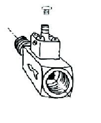
CHEMICAL INJECTOR & WATER CONNECTION ASSEMBLY
The solution Metering Tip
Connects to
hose to the
the water
machine
source
attaches here
Direction of flow
7PUMP MAINTENANCE:
Oil Change:
The first oil change is required after the first 50 hours of use. Impurities will get into the oil during
the break-in phase, and it is necessary to change the oil to remove the contamination that can lead to
premature pump wear. After this initial oil change, we recommend changing the oil in the pump
every three months or 300 hours of use.
NOTE: in locations with high humidity and/or wide, daily temperature ranges, it is possible for some
condensation to appear inside the pump crankcase. Condensation is evident if the oil looks white
and/or milky. While a small amount of condensation in the crankcase is not a problem, a large
amount of water in the oil (20% or more of the liquid is water) requires oil changes more frequently.
NOTE: the pump in your Torrent is in the front of the base compartment. The drain plug is located
on the left side of the pump, near the bottom. The dip stick (and oil fill port) is on the top of the
pump. The front of the pump contains an Oil Level Indicator that can be seen through a hole in the
front of the base compartment. The indicator is a clear view window with a yellow plate showing. A
red dot in the center of the yellow plate indicates the oil fill mark. The oil level should be at or just
slightly above the red dot.
NOTE: It is a good idea to run the pump for a few minutes before changing the oil, but be sure to
unplug the machine before you begin the process of changing the oil.
Use 11.8 ounces of SAE 15W-40 oil in your pump. Follow the steps below to correctly change the
oil in your Torrent pump.
1. Unplug the machine. Put the machine on a plastic sheet to protect the flooring surface from oil.
2. Open the latch and raise the tank. Prop the tank open so your hands are free to work on the
pump. Move the two hydraulic hoses that pass over the pump out of the way by disconnecting
them at the quick disconnects at unloader valve assembly.
3. Place a two-cup or larger container under the hole in the base, at the front of the machine, to
catch the oil as it drains from the pump.
4. Loosen the dip stick.
5. Loosen and remove the plug in the bottom of the left side of the pump. Let the oil drain out
until the pump is empty.
6. Remove the dip stick. NOTE: take care not to let oil drip onto the pump or other components.
7. Pour a few ounces of fresh oil into the pump, at the dip stick hole, and let it drain through to
flush out any impurities. Be careful not to spill any oil on the pump or elsewhere.
8. Replace the pump drain plug. Tighten.
9. Carefully pour about 11 ounces of fresh oil into the pump. Give it a little time to settle.
10. While watching the oil level at the Oil Indicator window (on the front of the pump head),
carefully pour a little more oil into the pump until the level reaches the red dot in the window.
11. Once the oil has reached the correct level, install the dip stick.
12. Clean up any/all oil that may have spilled or dripped inside the base of the machine.
13. Let the tank down. Move the machine away from the oil in the container on the floor.
14. Clean up any oil that has spilled. Pick up the container of drained oil, the plastic sheet, the oil
container(s) and dispose of all of it according to environmental regulations.TORRENT PUMP MAINTENANCE SCHEDULE
It is critical that you maintain your pump properly in order to get the performance and longevity that it
can provide.
Change the oil in your pump after the first 50 hours of operation, then follow this maintenance schedule.
TASK AS
DAILY WEEKLY NEEDED
X
Inspect and clean pump inlet filters
X
Check oil for correct level and consistency
Check pump for oil and water leaks
X
X
Check fittings for proper tightness
after the first one X
Change Oil every 300 hours at 50 hours
X
Packing Change
Valve Change
X
NOTE: if the oil shows signs of contamination (milky or discolored) change it immediately, and
replace the packings.
Keep a record of each task performed and the date completed.
GENERAL TROUBLESHOOTING
IF THIS CHECK THIS
Check the circuit breakers in the wall. If both cords were on one
circuit the breaker may have tripped.
Pump or Vac Does Not Turn On
The switches should light up when turned ON. Check the switch
to make sure it is working.
Check the spray tip(s) for proper size or excessive wear.
The pressure relief valve may be stuck open, or the seat may be
worn.
Pump Pressure is Low Check the inlet filters for dirt or debris.
The pump inlet or outlet valves may be dirty or damaged.
Make sure the tank lid is closed tightly, the drain hose is closed
Vacuum Suction is Low tightly, and the recovery hose is tight at the vac inlet hose barb
and at the tool.
Check the hose for cracks.
Water Leaking from Pump Worn packing in pump.
Worn piston seals.
Misaligned oil seal O-Ring.
Oil Leaking from Pump Bad bearing.
Damaged crankcase.10
9 16
15
10A 18
7
10B 10D
16
2 10C
1
11 19
3 4 0000
20
5
6 12
6A 22
21
13 14
23
24
27
28
26 48
35
35A 29
29
38 33
36 30
41A
38A 32 32
41
39 31
37 34
31
37A
40 45
40A
51 46
60 44
42
47
52A 59 43
63
52
62
6
48 6A
49A 58
49
50
55
53 53A 57
56
54 TORRENT
120V
2-5-2010TORRENT®
PART LIST
120V
ITEM # PART # DESCRIPTION ITEM # PART # DESCRIPTION
#1 196 Clamp, cable #40 1490 Filter, In-line with swivel
#2 166 Hose clamp #40A 164 Hose barb
#3 1349 Spacer #41 1489 Valve, thermal protection
#4 290 Washer, rubber #41A 221 Quick disconnect
#5 1350 Bracket, float #42 411A Fan, cooling
#6 230 Cord retainer #43 410 Guard, fan
#6A 230A Nut, plastic #44 1501 Plate, pump & motor mounting
#7 2068 Float, switch, 90° #45 FP526 Cover, rear
#9 1277 Hose Barb, 1-1/2” #46 2015 Guard
#10 1516 Elbow, ABS #47 1495 Transformer + ammeter (50)
#10A 1139 Elbow, 45º #48 908B Latch & strike
#10B 1140 Elbow, 90º #49 2166 Gauge, pump pressure
#10C 1524 Elbow, ABS 1-1/2 #49A 219 Quick disconnect, 1/4 fpt
#10D 1494 Bushing, ABS #50 1495 Ammeter + transformer (47)
#11 FP521A Strainer bag, vacuum inlet #51 237 Cap, with chain
#12 2069B Screen, pump inlet, 30 mesh #52 1184 Hose connector
#13 1168 Nipple, PVC #52A 1525 Plug, plastic
#14 FP522 Tank, recovery #53 1502,1547 Clamp collar, 2 pc, for unloader
#15 FP523 Cover, Vacuum Motors #53A 1522A Quick disconnect, female
#16 FP578 Switch, SPST, motor ON/OFF #54 905 Castor, 4”
#18 1434A Switch plate, Torrent, 120V #55 928B Louver, black, 3”
#19 227 Light, green, 240V #56 2084 Wheel, 10”
#20 423-120/240 Hour meter #57 27A Axle cap
#21 1130 Strap, velcro #58 910-24.5 Axle rod
#22 1060C Cap, drain hose #59 FP527 Base compartment, drilled
#23 1060B Hose, drain #60 1476 Strap, with grommets
#24 1518 Hose clamp #62 495A Power cord, 25 ft
#26 1129 Gasket, under lid #63 801 Hinge pin
#27 2070B Lid, recovery tank access
#28 408E Vacuum motor
#29 2013A Gasket, for vacuum motor
#30 MA-9 Manifold, vac motor
#31 1477 Gasket, under vac manifold
#32 929B Filter, ball float, vac shut-off Miscellaneous Parts & Assemblies
#33 1081 Elbow / hose barb FP525 Pump & motor, complete
#34 2067 Pump, auto-dump FP195D Vac hose & pressure line 25’
#35 1506 Hose, 21” 956A 50’ dump hose
#35A 1507 Hose, 17” 919D Hose, vacuum inlet
#36 1505 Hose, 15” FP497 Chemical injector
#37 1491 Motor, pump drive, no pump 56380989 Kit, metering tips
#37A FP524 Pump, complete with brass
#38 1513 Valve, pressure relief
#39 1488 Valve, pump unloader
#39A 1511 Vheck valve, backflow preventer
2-8-2010TORRENT ®
HARD SURFACE CLEANER
120V
NOTES:
208-772-0573 • 800-257-7982 • FAX: 208-772-0577
VISIT US AT: http://www.usproducts.comYou can also read