Rondò/Estelle 3-8 OF - Belle Comfort

Page created by Rick Benson
 
CONTINUE READING
Rondò/Estelle 3-8 OF - Belle Comfort
Rondò/Estelle 3-8 OF
      ISTRUZIONI PER L’INSTALLAZIONE E LA MANUTENZIONE

                                                         IT       FR        DE

                                                         ES       BE       RUS

                                                         PT       GR        RO

                                                        ENG       SL

Gentile Cliente,
metta in funzione la sua nuova caldaia entro 30gg dalla data di installazione. Potrà così
beneficiare, oltre alla garanzia legale, anche della garanzia convenzionale Sime (riportata
nelle ultime pagine del manuale).

Fonderie SIME S.p.A                                                  Cod. 6276050B - 07/2014
RONDO’ - ESTELLE
                                                                                                                                                                                                                         ENGLISH
FONDERIE SIME S.p.A. of Via Garbo 27 - Legnago (VR) - Italy declares that its diesel-burning boilers are produced in
accordance with the requirements of article 3 paragraph 3 of Directive PED 97/23/EEC and according to proper
manufacturing practice, as they are designed and manufactured in accordance with UNI EN 303 -1: 2002 standards.

CONTENTS

1     BOILER DESCRIPTION

1.1   INTRODUCTION . . . . . . . . . . . . . . . . . . . . . . . . . . . . . . . . . . . . . . . . . . . . . . . . . . . . . . . . . . . . . . . . . . . . . . . . . . . . . . . . . . . . . . . . . . .   34
1.2   DIMENSIONAL DETAILS
1.3   TECHNICAL FEATURES . . . . . . . . . . . . . . . . . . . . . . . . . . . . . . . . . . . . . . . . . . . . . . . . . . . . . . . . . . . . . . . . . . . . . . . . . . . . . . . . . . . . . 35
1.4   LOSS OF HEAD . . . . . . . . . . . . . . . . . . . . . . . . . . . . . . . . . . . . . . . . . . . . . . . . . . . . . . . . . . . . . . . . . . . . . . . . . . . . . . . . . . . . . . . . . . . . 36
1.5   FUNCTIONAL DIAGRAM
1.6   COMBUSTION CHAMBER . . . . . . . . . . . . . . . . . . . . . . . . . . . . . . . . . . . . . . . . . . . . . . . . . . . . . . . . . . . . . . . . . . . . . . . . . . . . . . . . . .               37
1.7   COMPATIBLE BURNERS

2     INSTALLATION

2.1   BOILER ROOM . . . . . . . . . . . . . . . . . . . . . . . . . . . . . . . . . . . . . . . . . . . . . . . . . . . . . . . . . . . . . . . . . . . . . . . . . . . . . . . . . . . . . . . . . . . . . 38
2.2   BOILER ROOM DIMENSIONS
2.3   CONNECTING UP SYSTEM
2.4   CONNECTING UP FLUE
2.5   FITTING THE CASING “RONDÒ”
2.6   ELECTRICAL CONNECTION . . . . . . . . . . . . . . . . . . . . . . . . . . . . . . . . . . . . . . . . . . . . . . . . . . . . . . . . . . . . . . . . . . . . . . . . . . . . . . . . . 39

3     USE AND MAINTENANCE

3.1   COMMISSIONING THE BOILER . . . . . . . . . . . . . . . . . . . . . . . . . . . . . . . . . . . . . . . . . . . . . . . . . . . . . . . . . . . . . . . . . . . . . . . . . . . . . . 40
3.2   LIGHTING AND OPERATION
3.3   REGULAR CLEANING
3.4   FROST POTECTION . . . . . . . . . . . . . . . . . . . . . . . . . . . . . . . . . . . . . . . . . . . . . . . . . . . . . . . . . . . . . . . . . . . . . . . . . . . . . . . . . . . . . . . . .    41
3.5   USER WARNINGS

                                                                                                                                                                                                                 33
1         BOILER DESCRIPTION

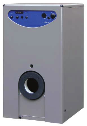
     1.1       INTRODUCTION                                     efficiency for economical performance.                    combustion hinged door, matchable with
                                                                                                                          a separate boiler unit “BA100 - BA150
     The new “RONDÒ - ESTELLE” series of cast                   This manual provides the instructions for                 - BA200”.
     iron boilers has been designed in compli-                  the following boiler models:
     ance with the Efficiencies Directive CEE                   – “RONDÒ” for central heating only, mat-              The components for “RONDÒ” installation
     92/42.                                                        chable with a separat e boiler unit                are supplied in three separate packages:
     They use light oil and have a perfectly bal-                  “BA100 - BA150 - BA200”                            boiler body, casing with enclosed docu-
     anced combustion with a very high thermal                  – “ESTELLE” for central heating only, with            ments and control panel.

     1.2       DIMENSIONAL DETAILS

                                   460                                           P                                             =                =

                                                                                                                    M
             850

                                                                                                                                                ø
                                                                                                                                                13
                                                                                                                                                  0
                                                                                                              625
                                                                                                                    505
                   277

                                                                                                                               S                        R

                                                                                                                                                         95
                               =              =                                                                                                55

                                                                                Rondò - Estelle
                                                        3 OF         4 OF           5 OF           6 OF       7 OF          8 OF
                          P    Depth                     415          515            615            715        815           915
                          M    C.H. flow                11/4”        11/4”          11/4”          11 / 4 ”   11/4”         11/4”
                          R    C.H. return              11/4”        11/4”          11/4”          11 / 4 ”   11/4”         11/4”
                          S    Boiler drain             1/2”         1/2”           1/2”           1/2”       1/2”          1/2”                               Fig. 1

     1.2.1     D.H.W. storage tank BA

                                    40             40                             40
                                                                                             50

                                         U C E                              C

                                                                                                                                     M2
                                                                                             895

                                                                                                                                         645

                                                                                                                                R3
                                                                                                    S4
                                                                                                                                   225

                                          505                           =              =

                                                  BA 100   BA 150     BA 200                                              BA 100         BA 150     BA 200
                   U     D.H.W. outlet             3/4”     3/4”       3/4”                  L     ø mm                    505            505         555
                   C     Re-circulation            3/4”     3/4”       3/4”                  H     mm                      845            1175       1265
                   E     D.H.W. inlet              3/4”     3/4”       3/4”                  A     mm                      225            225        235
                   M2    D.H.W. tank flow           1”       1”         1”                   B     mm                      645            685        825
                   R3    D.H.W. tank return         1”       1”         1”
                   S4    D.H.W. tank drain cock    1/2”     1/2”       1/2”
                                                                                                                                                             Fig. 1/a

34
1.3     TECHNICAL FEATURES

                                                                              RONDÒ - ESTELLE                                      BA tank
                                           3 OF         4 OF           5 OF         6 OF                7 OF       8 OF      100   150     200
Output
Minimum                           kW       18.9         24.5           32.5              41.7           49.9       57.9       –      –      –
Maximum                           kW       23.5         31.3           40.0              48.1           57.5       66.5       –      –      –
Input
Minimum                           kW       21.1         27.2           36.0              46.1           55.0       64.4       –      –      –
Maximum                           kW       26.2         34.8           44.3              53.1           63.3       74.0       –      –      –
Sections                           n°       3            4              5                 6              7          8         –      –      –
Maximum water head                bar       4            4              4                 4              4          4         –      –      –
Water content                        l     12.8         16.8           20.8              24.8           28.8       32.8       –      –      –
Smokes loss of head
Minimum/Maximum                 mbar     0.05/0.11 0.12/0.16         0.15/0.21      0.30/0.35        0.32/0.43   0.48/0.80    –      –      –
Water loss of head*             mbar         5         10                15             20               25          30       –      –      –
Combustion chamber pressure     mbar       –0.02     –0,02              –0,02         –0,02            –0,02       –0,02      –      –      –
Suggested chimney depression    mbar     0.07/0.13 0.14/0.18         0.17/0.23      0.32/0.37        0.34/0.45   0.50/0.82    –      –      –
Smokes temperature
Minimum/Maximum                    °C    160/185     160/185         160/185        160/170          160/170     164/174      –      –      –
Smokes flow
Minimum/Maximum                m3n/h     24.0/31.6 32.4/41.4        42.9/52.8       54.8/63.3        65.5/73.8   74.0/82.0     –     –     –
Smokes volume                    dm3         9         12               15              18               21          24        –     –     –
CO2                                 %       12.5     12.5              12.5            12.5             12.5        12.5       –     –     –
C.H. adjustment range              °C     30÷85     30÷85            30÷85           30÷85            30÷85       30÷85        –     –     –
D.H.W. adjustment range            °C        –          –                –               –                –           –      30÷65 30÷65 30÷65
D.H.W. flow rate ∆t 30°C**        l/h        –          –                –               –                –           –       918   990 1308
D.H.W. tank capacity                 l       –          –                –               –                –           –       100   150   200
D.H.W. maximum water head         bar        –          –                –               –                –           –        6     6     6
Weight                             kg       109       135              161             186              212         238       82    102   122
* With ∆t 10°C                  ** With the sanitary water at inlet temperature 15°C - Boiler temperature 80°C

RONDÒ/ESTELLE technical features - NOx: Class 3 (Burner with low polluting emissions)

                                                           3 OF                  4 OF                 5 OF           6 OF           7 OF
Output
Minimum                                       kW            –                    18.0                 27.5           36.2           45.0
Maximum                                       kW           19.7                  27.6                 32.8           45.7           55.1
Input
Minimum                                       kW            –                    20.0                 30.5           40.0           49.6
Maximum                                       kW           21.9                  30.7                 36.3           50.5           60.7
Sections                                       n°           3                     4                    5              6              7
Maximum water head                            bar           4                     4                    4              4              4
Water content                                    l         12.8                  16.8                 20.8           24.8           28.8
Pérdidas de carga lado humos
Minimum                                     mbar             –                    0.04                0.08           0.20            0.22
Maximum                                     mbar           0.06                   0.07                0.13           0.31            0.44
Water loss of head (∆t 10°C)                mbar            5                      10                  15             20              25
Combustion chamber pressure                 mbar          –0.02                  –0.02               –0.02          –0.02           –0.02
Suggested chimney depression
Minimum                                     mbar             –                   0.06                 0.10           0.22           0.24
Maximum                                     mbar           0.08                  0.09                 0.15           0.33           0.46
Smokes temperature
Minimum                                        °C           –                    110                  130            140            155
Maximum                                        °C          140                   145                  145            155            180
Smokes flow
Minimum                                    m3n/h            –                   24.3                  36.8           48.7           59.5
Maximum                                    m3n/h           26.8                 37.4                  43.9           61.5           72.8
Smokes volume                                dm3            9                    12                    15             18             21
CO2                                            %           12.8                 12.8                  12.9           12.8           13.0
C.H. adjustment range                         °C          30÷85                30÷85                 30÷85          30÷85          30÷85
Weight                                        kg           109                  135                   161            186            212

                                                                                                                                                 35
1.4   LOSS OF HEAD

                                                                                                                                                         RONDO’ - ESTELLE OF
                                    (mbar)
                                              25

                                (mbar)
                                                                                         RONDO’- ESTELLE 8 OF

                          di carico
                      of head

                                                                                                                    RONDO’- ESTELLE 7 OF
                  Perdite

                                              20
                 Loss

                                                                                                              RONDO’- ESTELLE 6 OF

                                              15
                                                                                                     RONDO’- ESTELLE 5 OF

                                              10
                                                                                        RONDO’ - ESTELLE 4 OF

                                              5
                                                                             RONDO’ - ESTELLE 3 OF

                                                   0              1000   2000            3000                4000             5000            6000

                                                                                                                                   Flow (l/h)
                                                                                                                                    Portata (l/h)

                                                                                                                                                                                Fig. 2

     1.5   FUNCTIONAL DIAGRAM

                 U
                 C
                 E                                                                              13
                                                             12                                                          2
                                                                                                         6                                                  3
                                                                                 M
                                                                                                                                                         60
                                                                                                                                                    40          80
                                                                                                                                                    20         100
                                                                                                                                                     0      120

                                                                          8                          6
                                             11

                                                                                              7          5

                                              9                                           R
                                             10                                                      4                                                   1

                                   KEY                                   5    Non-return valve                      10   D.H.W. storage tank
                                    1             Burner                 6    Automatic air vent                    11   D.H.W. tank expansion vessel
                                    2             Boiler                 7    D.H.W. pump                           12   D.H.W. tank safety valve
                                    3             Boiler thermometer     8    Magnesium anode                       13   Hydrometer
                                    4             Boiler drain           9    D.H.W. tank drain
                                                                                                                                                                               Fig. 2/a

36
1.6     COMBUSTION CHAMBER

The combustion chamber is of the straight
flow type and complies with standard EN
303-3 appendix E.
The dimensions are shown in fig. 3.

                         L       Volumen
                        mm         dm3
Rondò/Estelle 3 OF      305        17.5
Rondò/Estelle 4 OF      405        24.0
Rondò/Estelle 5 OF      505        30.5
Rondò/Estelle 6 OF      605        37.0

                                                                                     280
Rondò/Estelle 7 OF      705        43.5
Rondò/Estelle 8 OF      805        50.0

1.7     COMPATIBLE BURNERS

In general, the oil burner that is compatible
with the boiler should use spray                                   270                                                L
of the semi solid type.
Sections 1.7.1- 1.7.2 shows the matching
table of the burners together with the boi-                                                                                               Fig. 3
lers have been tested with.

1.7.1   “RIELLO” burners

                              Model                       Nozzle                               Atomising                  Pump pressure
                                                 Type     P min      P max                       angle              P min         P max
                                                            ø           ø                  P min      P max          bar           bar
Rondò/Estelle 3 OF         RG0.1R               DELAVAN   0.50        0.60                 60°W       60°W           11.5          12.0
                         R2000 G26 R            DANFOSS   0.50        0.55                 60°S       60°S          10.5           12.0
Rondò/Estelle 4 OF          RG1R                DELAVAN   0.65        0.75                 80°W       60°W          12.5           13.0
                         R2000 G38 R            DELAVAN   0.60        0.75                 80°W       60°W          13.0           12.5
Rondò/Estelle 5 OF          RG1R                DELAVAN   0.85        1.00                 60°W       60°W           11.5          11.5
                         R2000 G46 R            DELAVAN   0.75        0.85                 80°W       60°W          13.9           14.0
Rondò/Estelle 6 OF           RG2                DELAVAN   1.00        1.10                 60°W       60°W          10.0           10.0
                         R2000 G120             DELAVAN               1.10                            60°W                         12.0
Rondò/Estelle 7 OF           RG2                DELAVAN    1.10       1.25                 60°W       60°W            11.0         11.0
                         R2000 G120             DELAVAN               1.25                            60°W                         13.0

1.7.2   “SIME” burners

                              Model                       Nozzle                               Atomising                  Pump pressure
                                                 Type     P min      P max                       angle              P min         P max
                                                            ø          ø                   P min      P max          bar           bar
Rondò/Estelle 8 OF            MACK 6            DELAVAN    1.25          1.50              60°W       60°W            11.0         12.5

1.7.3   “SIME” burners - NOx: Class 3 (Burner with low polluting emissions)

                              Model                       Nozzle                               Atomising                  Pump pressure
                                                 Type     P min      P max                       angle              P min         P max
                                                             ø          ø                  P min      P max          bar           bar
Rondò/Estelle 3 OF      BLUE MACK 1 LC          DANFOSS   0.50        0.50                 80°H       80°H          12.0           12.0
Rondò/Estelle 4 OF      BLUE MACK 1 LC          DANFOSS   0.65        0.65                 60°S       60°S          12.0           12.0
Rondò/Estelle 5 OF      BLUE MACK 2 LC          DANFOSS   0.75        0.75                 60°H       60°H          12.0           12.0
Rondò/Estelle 6 OF      BLUE MACK 2 LC          DANFOSS    1.10       1.10                 60°H       60°H          12.0           12.0
Rondò/Estelle 7 OF       BLUE MACK 3            DANFOSS   1.25        1.25                 60°S       60°S          10.0           12.8
NOTE: The best emission values are obtained with Danfoss 60°H nozzles. Use of Danfoss 60°H nozzles is recommended in the field to ensure
continued dependable burner functioning.

1.7.4 Burners assembly (fig. 4)
                                                                                M8

The boiler door details is shown in figure 4                                                                  ø 110
for burner mounting.
The burners must be regulated such that
the CO2 value is that indicated in point 1.3,                                                                 R7
with a tolerance of ± 5%.                                                                                       5                         Fig. 4

                                                                                                                                                   37
2        INSTALLATION

     2.1      BOILER ROOM                             The magnesium anode must be checked                       greater than the uplift force of combus-
                                                      annually and replaced if it is worn.                      tion gases, the exhaust outlet should be
     The boiler room should feature all the char-     Fit a safety valve calibrated to 6 bar on the             at least 0.4 m higher than structures
     acteristics required by standards governing      tubing of the cold water supply to the boiler             adjacent to the stack (including the roof
     liquid fuel heating systems.                     unit (12 fig. 2).                                         top) within 8 m;
                                                      n case the system pressure is excessive fit             – have a diameter that is not inferior to
                                                      an appropriate pressure reducer. If the                   that of the boiler union: square or rec-
     2.2      BOILER ROOM DIMENSIONS                  safety valve calibrated to 6 bar frequently               tangular-section flues should have an
                                                      intercepts, fit an expansion vessel with a                internal section 10% greater than that of
     Position the boiler body on the foundation       capacity of 8 litres and a maximum pres-                  the boiler union;
     bed, which should be at least 10 cm high.        sure of 8 bar (11 fig. 2). The tank should be           – the useful section of the flue must con-
     The body should rest on a surface allowing       of the membrane type, made of natural rub-                form to the following formula:
     shifting, possibly by means of sheet metal.      ber “caoutchouc”, which is suitable for
                                                                                                                               P
     Leave a clearance between the boiler and         foods.                                                     S   = K
     the wall of at least 0.60 m, and between the                                                                              √H
     top of the casing and the ceiling of 1 m
     (0.50 m in the case of boilers with incorpo-     2.4    CONNECTING UP FLUE                                 S    resulting section in cm2
     rated D.H.W. tank). The ceiling height of the                                                              K    reduction coefficient for liquid fuels:
     boiler room should not be less than 2.5 m.       The flue is of fundamental importance for the                  – 0.045 for firewood
                                                      proper operation of the boiler; if not installed               – 0.030 for coal
                                                      in compliance with the standards, starting                     – 0.024 for light oil
     2.3      CONNECTING UP SYSTEM                    the boiler will be difficult and there will be a               – 0.016 for gas
                                                      consequent formation of soot, condensate                  P    boiler input in kcal/h
     When connecting up the water supply to           and encrustation. The flue used to expel com-             H    height of flue in meters, measured
     the boiler, make sure that the specifications    bustion products into the atmosphere must                      from the flame axis to the top of the
     given in fig. 1 are observed. All connecting     meet the following requirements:                               flue reduced by:
     unions should be easy to disconnect by           – be constructed with waterproof materi-                       – 0.50 m for each change of direc-
     means of tightening rings. A closed expan-          als, and resistant to smoke temperature                        tion of the connection union
     sion tank system must be used.                      and condensate;                                                between boiler and flue;
                                                      – be of adequate mechanical resilience and                     – 1.00 m for each metre of union
                                                         of low heat conductivity;                                      itself.
     2.3.1    Filling the water system                – be perfectly sealed to prevent cooling of
                                                         the flue itself;
     Before connecting the boiler, thoroughly         – be as vertical as possible; the terminal              2.5     FITTING THE CASING “RONDÒ”
     flush the system to eliminate scale which           section of the flue must be fitted with a
     could damage the appliance.                         static exhaust device that ensures con-              The casing and the control panel are sup-
     Filling must be done slowly to allow any air        stant and efficient extraction of products           plied in separate cardboard packages.
     bubbles to be bled off through the air valves.      generated by combustion;                             The housing package also contains the boil-
     In closed-circuit heating systems, the cold      – to prevent the wind from creating pres-               er documents and the glass wool for insu-
     water filling pressure and the pre-charging         sure zones around the chimney top                    lating the cast iron body. To fit the casing,
     pressure of the expansion vessel should be
     no less than or equal to the height of the
     water head of the installation (e.g. for water
     head of 5 meters, the vessel pre-charging
     pressure and installation filling pressure
     should be at least 0.5 bar).
                                                                                                                              12

                                                                                     6
     2.3.2    Characteristics of feedwater
                                                                                                                                       4
                                                                                      7
     Water supplying the heating circuit must
     be treated in accordance with UNI-CTI                                                                                5
     8065 standards.
     It is absolutely essential to treat water in                                                                                      9
     the heating system in the following cases:
     – For extensive systems (with high con-
                                                                            2                                                               8
         tents of water).
     – Frequent addition of water into the system.
     – Should it be necessary to empty the sys-
         tem either partially or totally.

                                                                                                     11
     2.3.3    D.H.W. storage tank

     The “RONDÒ -ESTELLE ” boilers may be                                                                             1
     matched with the separate boiler units                                                               1
     “BA100 -BA150 -BA200 ”.                                                                 9
     The glass enamelled D.H.W. storage tank                                                 3
     comes with a magnesium anode to protect
     the boiler and an inspection flange for
                                                                                                                                                    Fig. 5
     checking and cleaning.

38
proceed as follows (fig. 5):
                                                                                                 KEY                                                                                              B1     Permanent Feeding Burner (not supplied)
– fit the lower front (1) and back (2)                                                           L     Line                                                                                       TA     Room stat
  brackets to the heads with the four TE                                                         N     Neutral                                                                                    OP     Programmer's clock (optional)
  screws supplied;                                                                               IG    Main switch
– insert the upper bracket (5) fixing it to                                                      TS    Safety stat                                                                                NOTE: When a room stat is to be fitted remove
  the front head with the two TE screws.                                                         TC    Boiler stat                                                                                the link between terminal 4 and 5 on the connec-
– insulate the cast iron body with glass                                                         SA    Green voltage LED                                                                          tor plug. To connect the programmer's clock
  wool, fixing it with the two springs sup-                                                      P     C.H. pump                                                                                  (OP), remove the link between terminals 5 and 8.
  plied;                                                                                         B     Direct Feeding Burner (not supplied)
– assemble the panel (11) making sure
  that the TE screws are already fitted on
  the combustion chamber door.

                                                                                                       MARRONE-BROWN
– fit the left side (3) and the right side (4)

                                                                                                                                                                                                                                               MARRONE-BROWN
  by inserting them in the tangs on the

                                                                                                                                                                                                                 GRIGIO-GREY
                                                                                                                                             GRIGIO-GREY
                                                                                                                              BLU-BLUE
  brackets (1-2) depending on the model.

                                                                                                                                                                                                                                    BLU-BLUE
– fix the sides to the upper brackets (5 - 1)
  with the four self-tapping screws sup-
  plied;
– fit the two back panels (6) and (7) of the                                                                                                                                                                                   NOTE: The brown (capped off)
  sides with the ten self-tapping screws                                                                                                                                                                                       cable has to be exclusively used
  supplied;                                                                                                                                                                                                                    in case of permanent feeding
                                                                                                                                                                                                                               burners (type B1).
– fit the control panel (9) inserting the two
  lower tangs of the panel on the drains on
  the sides, and fix it with the four self-tap-
  ping screws supplied. Before carrying
  out this operation unwind the capillaries
  of the two thermostats and the thermo-
  meter and place the respective feelers
  in the sheath (10), fixing all with a capil-
  lary pin;
                                                                                                                                                                                                                                                                 Fig. 6
– fit the front panel (8) fixing it to the sides
  with pin clutches;
– complete the assembly by fixing the lid                                                      by fuses.                                                                                               2.6.1            Electrical connection
  (12) to the sides with pin clutches.                                                         The room thermostat (required for                                                                                        to the BA boiler unit
                                                                                               enhanced room temperature control)
NOTE: Remove the “Testing Certificate”                                                         should be installed as shown in fig. 6.                                                                 To connect the boiler to the boiler unit pro-
from inside the combustion chamber and                                                         Connect the burner with the cable supplied.                                                             ceed with the following operations:
keep together with the instructions manual.                                                                                                                                                            – remove the casing lid of the boiler and
                                                                                               NOTE:                                                                                                     the back protection of the control panel
                                                                                               Device must be connected to an efficient                                                                  in order to have access to the terminal
2.6      ELECTRICAL                                                                            earthing system.                                                                                          board of the boiler;
         CONNECTION                                                                            SIME declines all responsibility for injury                                                             – remove the protection of the boiler unit
                                                                                               caused to persons due to failure to earth                                                                 to have access to the terminal board of
The boiler is fitted with an electricity cable,                                                the boiler. Always turn off the power sup-                                                                the boiler unit (fig. 7);
and requires a 1ph - 230V - 50Hz power                                                         ply before doing any work on the electri-                                                               – connect the cables as shown in the dia-
supply through the main switch protected                                                       cal panel.                                                                                                gram (fig. 6/a).

                                                B1                                                                                                                                                     KEY
                                                                                                                                                                                                       L       Line
          B4                     1                             1
                                                                                                                                                                                                       N       Neutral
                                                                                                                                                                                                       IG      Main switch
               GRIGIO-GREY

                                 BLU-BLUE

                                                         MARRONE-BROWN

                                                                                                                                                                                          TB           TS      Safety stat
                                                                                                                                                                        PB                C            TC      Boiler stat
                                                                                                                                                                                      2       1
                                                                                                                                                                                                       SA      Green voltage LED
                                                                                                                                                           PI                                          P       C.H. pump
                                                                                                                                                                                                       B1      Permanent Feeding Burner
                                                                                                                                                                                                               (not supplied)
                                                                                                                                                                                                       OP      Programmer's clock (optional)
               L             N              1   2    3                   4   5    6   7   8   9 10                        L              N                 1    2        3        4   5   6            PB      D.H.W. pump
                                                                                                                                                                                                       TB      D.H.W. stat
                                                                                                                                                                                                       R       Relais
                                                    TS                           SA                                                                                                                    NOTE: To connect the ambient thermo-
         IG                                                                                                                                                    NC            NA
                                                                                                                                                                                                       stat (TA), remove the link between termi-
                                                                                                                                                                                      R
                                                                                                                                                                    C                                  nals 1-5 of the boiler unit terminal block.
                                                                             OP
                                                                                                                                                                                                       Remove links 4-5 and 8-9 from the boiler
                                                                                                                                                                                                       terminal block.
                                 TC                                                                                                                                                                    To connect the programmer's clock (OP),
                                                                                                                                                                                                       remove the link between terminals 5-8.

                                                RONDÒ’ - ESTELLE                                                       BA100 - BA150 - BA200 storage tank
                                                                                                                                                                                                                                                               Fig. 6/a

                                                                                                                                                                                                                                                                          39
3        USE AND MAINTENANCE

     3.1      COMMISSIONING THE BOILER
                                                             RONDÒ - ESTELLE
     When commissioning the boiler always
     make sure that:                                                 2              4        3      1                              5
     – the system has been filled with water and
       adequately vented;
     – the flow and return valves are fully open;
     – the flue and chimney are free from
       obstructions;
     – the electrical connections to the mains
       and the earthing are correct;
     – no flammable liquids or materials are
       near the boiler;
     – check that the circulating pump is not
       locked.

     3.2      LIGHTING AND OPERATION

     3.2.1    Lighting the boiler (fig. 7)

     To light the boiler proceed as follows:                                                        BA100 - BA150 - BA200 storage tank
     – check that the “Testing Certificate” has              KEY
        been removed from inside the combus-                  1    Main switch
        tion chamber;                                         2    Safety stat
     – switch on the main switch (1) and verify               3    Green voltage LED
        that the green LED (3) turns on to con-               4    Boiler thermometer                   9                                7
                                                              5    Boiler stat
        firm the presence of voltage.The burner                                                                                          8
        will start;
                                                              6    D.H.W. stat                          6
                                                              7    D.H.W. tank thermometer
     – turn the boiler stat knob (5) to a temper-             8    Bulb holder thermostat/          10
        ature no lower than 60°C. The set tem-                     D.H.W. tank thermometer
        perature value can be checked on the                  9    Relais
        thermometer (4).                                     10    Connector plug
     – set the temperature of the hot-water
        service by pressing the thermostat of
        the boiler unit (6). The set temperature                                                                                              Fig. 7
        value can be checked on the thermome-
        ter (7).

                                                         tral heating plant off;                        electrical supply before servicing or main-
     3.2.2    Safety stat (fig. 7)                     – empty the central heating plant if there       tenance is carried out.
                                                         is danger of frost:
     The manually reset safety stat (2) trips to
     switch-off the burners immediately when                                                            3.3.1    Smoke side boiler (fig. 8)
     the boiler temperature exceeds 100°C. To          3.3         REGULAR CLEANING
     restart the boiler, unscrew the black cover                                                        To carry out cleaning of the smoke pas-
     and press the button underneath. If the           Maintenance of the boiler should be car-         sages remove the screws that fix the door
     problem occurs frequently, call an autho-         ried out annually by an authorised service       to the body of the boiler and with the special
     rised technical assistance centre for the         engineer. Disconnect the boiler from the         cleaning brush clean the internal surfaces
     necessary checks to be carried out.

     3.2.3    System filling                                                                                              RONDO' 3/4 OF
                                                                                                                          ESTELLE 3/4 OF
     Periodically check the pressure values of
     the hydrometer (13 fig. 2/a) mounted onto
     the system, when the system is cold, should
     range between 1 and 1.2 bar. If the pres-
     sure is less than 1 bar, reset the system.

                                                                                                                          RONDO' 5/6 OF
     3.2.4    Turnig OFF boiler (fig. 7)                                                                                  ESTELLE 5/6 OF

     To temporarily turn off the boiler turn off
     the electricity supply by pressing the main
     switch (1). The following operations must be
     carried out if the plant will not be in use for
     a lengthy period of time:
     – position the main switch of the plant on off;                                                                                          Fig. 8
     – turn the fuel and water taps of the cen-

40
and the smoke evacuation tube well, remov-
ing any deposits.
Once the maintenance is compled, the baf-
fles have to be fitted onto the original posi-
tions (ref. “RONDÒ/ESTELLE 3-4-5-6 OF”
models). In the “ESTELLE” versions the
maintenance operations can be carried out
without removing the burner.
                                                    ESTELLE
                                                                                                                       12

3.3.2     Tank unit protection anode                                         6

                                                                                                                                4
The tank unit comes with a protection mag-                                   7
nesium anode (fig. 9). This non-rust anode in
normal operating conditions has life span of                                                                       5
5 years. It is, however, advisable to check
the erosion annually and replace it if worn.
                                                                                                                                9
To disassemble the tank unit flange (1),
remove the cover (5) and unscrew the two
nuts that fix the upper cover (4). Then lift                        2                                                                8
the upper cover (4) which is simply inserted
with pressure.

                                                                                             11

                                                                                                               RONDO’
                                   5
                                                                                                  1            1
                                   1
                                                                                     9
                                   2                                                                           ESTELLE
                                                                                     3
                                   3      4                                                                1

                                                                                                                                         Fig. 10

                                                 3.3.4   Fault finding                                bration and the function of the appliance.
    KEY
     1    Tank unit flange
                                                 Herefater we outline a number of potential       Difficulty in regulating the burner and/or
     2    Gasket
     3    Magnesium anode ø 33x185
                                                 problems that may occur on the appliance         lack of yield
     4    Cover                                  and the relevant list of actions required. A     – Check: the regular flow of fuel, the clean-
     5    Protection                             working fault, in most cases, provocates            ness of the boiler, the non obstruction of
                                                 the “lock out” signal onto the control panel        the smoke duct, the real input supplied
                                       Fig. 9
                                                 of the control box.                                 by the burner and its cleanness (dust).
                                                 When this light turns on, the burner can
                                                 operate again only after the reset button        The boiler gets dirty easily
3.3.3     Disassembly of the casing              has been pressed; if this has been done          – Check the burner regulator (smoke
                                                 and a regular ignition occurs, it means the        analysis), the fuel quantity, the flue
To disassemble the casing of the boiler, pro-    failure can be defined momentary and not           obstruction and the cleanness of the air
ceed as follows (fig. 10):                       dangerous. On the contrary, if the “lock out”      duct of the burner (dust).
– remove the cover (12) fixed with pin clut-     stays, the cause of the fault, as well as the
   ches;                                         relevant action must be made according to        The boiler does not heat up
– remove the panel (8) which are fixed to        the following chart:                             – Control the cleanness of the shell, the
   the sides by pin clutches;                                                                       matching, the adjustment, the burner
– remove the control panel (9) whose sides       The burner does not ignite                         performances, the pre-adjusted temper-
   are fixed by four self-tapping screws;        – Check the electric connections.                  ature, the correct function and position
– remove the back panels (6) and (7)             – Check the regular fuel flow, the clean-          of the regulation stat.
   which are fixed to the sides by ten self-       ness of the filters, of the nozzle and air     – Make sure that the boiler is sufficiently
   tapping screws;                                 vent from the tube.                              powerful for the appliance.
– disassemble the left side (3) unscrewing       – Check the regular spark ignition and the
   the screws fixing it to the upper bracket       proper function of the burner.                 Smell of unburnt products
   (5), and remove the screws that fix it to                                                      – Control the cleanness of the boiler shell
   the lower bracket (1);                        The burner ignites regularly but the flame         and the flue, the airtightness of the boiler
– disassemble the right side (4) following       goes out immediately                               and of the flue ducts (door, combustion
   the same operations.                          – Check the flame detection, the air cali-         chamber, smoke ducts, flue, washers).

                                                                                                                                                   41
– Control the quality of the fuel.

     Frequent intervention of the boiler shut-
     off valve
     – Control the presence of air in the sys-
        tem, the function of the circulation
        pumps.
     – Check the load pressure of the appli-
        ance, the efficiency of the expansion
        tanks and the valve calibration.

     3.4      FROST PROTECTION

     In the event of frost, ensure that the central
     heating plant is functional and effective
     frost protection interlocks are in place to
     protect against frost damage

     3.5      USER WARNINGS

     When faults occur and/or the equipment
     does not operate correctly, turn the boiler off
     and contact the authorised service engineer.

42
You can also read