PHYSICAL REVIEW LETTERS 122, 036101 (2019) - Physics (APS)
←
→
Page content transcription
If your browser does not render page correctly, please read the page content below
PHYSICAL REVIEW LETTERS 122, 036101 (2019)
  Featured in Physics

                        Nanomolding of Crystalline Metals: The Smaller the Easier
                        Ze Liu,1,2,* Guoxing Han,1 Sungwoo Sohn,3 Naijia Liu,3 and Jan Schroers3,†
       1
      Department of Engineering Mechanics, School of Civil Engineering, Wuhan University, Wuhan, Hubei 430072, China
   2
   State Key Laboratory of Water Resources and Hydropower Engineering Science, Wuhan University, Wuhan 430072, China
     3
       Department of Mechanical Engineering and Materials Science, Yale University, New Haven, Connecticut 06511, USA

                                           (Received 8 July 2018; published 22 January 2019)

                 We report on a thermomechanical nanomolding method for crystalline metals. Quantified by the aspect
              ratio, this process becomes easier with decreasing mold diameter. As the responsible underlying diffusion
              mechanism is present in all metals and alloys, the discovered nanomolding process provides a toolbox to
              shape essentially any metal and alloy into a nanofeature. Technologically, this highly versatile and practical
              thermomechanical nanomolding technique offers a method to fabricate high-surface-area metallic nano-
              structures which are impactful in diverse fields of applications including catalysts, sensors, photovoltaics,
              microelectronics, and plasmonics.

              DOI: 10.1103/PhysRevLett.122.036101

   Molding is a manufacturing process in which a pliable or            easier with decreasing mold size, and that essentially any
moldable material is formed to replicate a mold. It is used            metal can be molded into high-aspect-ratio and single
as a processing technique for all major material classes, and          crystal nanorods, as we show and explain, through TMNM
as the most versatile manufacturing technique for the                  with CMs.
shaping of thermoplastics. The moldability of a material                  Introduced nanomolding with crystalline metals is a
is typically associated with its flowability. Such flowability         thermomechanical process [Fig. 1(a)], where a piece of
is high in thermoplastics, gels, and some glasses; however,            crystalline metal is formed against a hard mold under a
it is low in crystalline metals [1,2]. Metals are either too           pressure (typically p ≥ 100 MPa) and temperature (typi-
hard in their crystalline state or too fluid and reactive              cally T ≥ 0.5T m ). By using this method, crystalline metals
in their liquid state to be considered for molding. The                can be molded into millimeter, micrometer, and nano-
difficulty of a shape to be molded can be quantified in the            meter sized features [Fig. 1(b)]. For identical molding
aspect ratio between the mold cavity depth, L, and the mold            conditions, the ease of molding, quantified by the aspect
cavity diameter, d. In general, molding is increasingly                ratio (L=d) of the molded rods increases rapidly with
challenging with decreasing d, which can originate from                decreasing mold cavity [Figs. 1(b) and 1(c); similar results
capillary forces [3] or intrinsic size effects, typically related      are shown in Fig. S1 of the Supplemental Material [17] for
to the length scale of flow units [4]. Such flow units can             TMNM with Fe]. This suggests that TMNM with CMs
be grains in crystalline metals (typically microns) or chain           becomes easier with decreasing mold cavity. This is in
length in plastics (typically nanometers), or shear trans-             opposition to other nanomolding methods such as thermo-
formation zones in metallic glasses (typically ∼1 nm).                 plastic molding of metallic glasses [3,4,18,19], laser shock
Therefore, attempts to mold on the nanoscale have been                 imprinting [20], liquid printing [21], and dip-pen nano-
limited to thermoplastics [2,5–8], gels [9–11], and glasses            lithography [22], for which smaller and higher aspect-ratio
[12–15] due to their high moldability and small flow units.            features are typically increasingly challenging.
Crystalline metals were not considered until recently, where              In general, the dominated deformation mechanism for
we reported the first evidence that, at a high temperature of          crystalline metals can be either dislocation slip [23,24],
∼0.6T m , some crystalline metals can be shaped into                   twining [25,26], or grain boundary sliding or rotation
nanorods [16]. Here, we uncover the underlying mecha-                  [27,28], depending on the grain size [29]. In our experi-
nism for thermomechanical nanomolding with crystalline                 ments, very few twins are present in the prepared metallic
metals (TMNM with CMs) as a diffusion dominated                        nanorods, and the mold dimension is large compare to the
mechanism driven by the vacancy concentration gradient                 grain size [16]. Therefore, we can rule out twining, grain
which follows the pressure gradient. Diffusion can occur               boundary sliding or rotation dominated deformation mech-
either through a bulk or a surface-interface process, and the          anisms. On the other hand, dislocation nucleation and
ratio of the effectiveness of the two processes depends on             movement will become increasingly less effective with
the mold diameter and the mold-metal combinations. The                 decreasing mold size since the dislocation nucleation rate
scaling of the two processes (L=d ∝ 1=d for bulk and                   decreases sharply with decreasing mold diameter [30,31].
L=d ∝ 1=d3=2 for surface) suggests that molding becomes                Hence, the observed “the smaller the easier” quality of

0031-9007=19=122(3)=036101(6)                                  036101-1                          © 2019 American Physical Society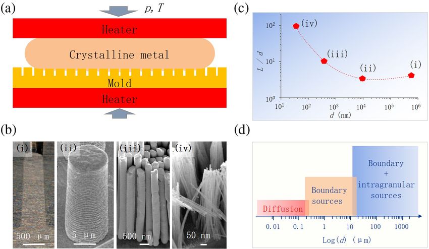
PHYSICAL REVIEW LETTERS 122, 036101 (2019)

                                                                      FIG. 2. Deformation mechanism of TMNM with CMs com-
                                                                      pared to other nanomolding mechanisms. (a) Moldability, quan-
                                                                      tified by L=d, scales qualitatively differently for bulk metallic
                                                                      glasses (black solid squares; the data are from Ref. [4]), and for
FIG. 1. Scaling of thermomechanical molding with crystalline
                                                                      crystalline metals (red solid pentagons; the dashed-red line is a
metals. (a) Schematics of the experimental setup of TMNM with
                                                                      guide for the eye). The processing of Au nanorods was carried out
CMs. (b) Thermomechanical molding, taking Ag as an example,
                                                                      at 622 °C under ∼800 MPa for 100 s. The Hagen-Poiseuille law
with millimeter, micrometer, and nanometer size molds, using
                                                                      (H-P law) with capillary force where γ ¼ 1 N=m and θ ¼ 120°
molding pressure, temperature, and time of 100 MPa, 620 °C, and
                                                                      [10] (magenta line) and without capillary force (blue line) are
100 s, respectively. Examples of prepared Ag rods with diameters
                                                                      calculated. The molding time and loading pressure are 180 s and
of 0.57 mm, 10 μm, 375 nm, and 36 nm are shown in (i)–(iv).
                                                                      ∼350 MPa, respectively, taken from Ref. [4]. The discrepancy
(c) Aspect ratio of the molded Ag rods as the function of mold
                                                                      between theory (magenta line) and experiments (black solid
diameter (d) (the dashed-red line is given as a guide for the eye).
                                                                      squares) is attributed to an enhanced viscosity on the nanoscale
(d) The various dominant deformation mechanisms at play during
                                                                      [4]. (b) Calculated growth rates for the diffusion driven growth of
thermomechanical molding at various length scales. Plastic
                                                                      Au nanorods at 500 °C [Eq. (2), red and purple lines]. Viscous
deformation of metals is generally associated with dislocations
                                                                      flow based mechanisms with and without the capillary effect for
from grain boundary sources and intragranular sources such as
                                                                      nanomolding of Pt-BMG are also plotted for comparison [Eq. (1),
grain sliding and rotating. These processes become decreasingly
                                                                      black and dashed-black lines). The loading pressure and aspect
and rapidly less effective with decreasing mold size. Hence,
                                                                      ratio are 500 MPa and λ ¼ 5, respectively. The other parameters
diffusion becomes the dominant deformation mechanism on the
                                                                      are taken from the literature and are listed in Table S1 of the
nanoscale.
                                                                      Supplemental Material [17]. (c) Growth of Au nanorods at 500 °C
                                                                      and ∼500 MPa versus molding time. The dots represent the
TMNM with CMs must originate from another mechanism.                  experimental data and the solid line is fitted according to
We suggest, and then quantify, that a mechanism based on              Eq. (3).
diffusion is the underlying mechanism [Fig. 1(d)].
   Typically during nanomolding of thermoplastics, gels,              BMGs is qualitatively different from TMNM with CMs.
and glasses, a decrease of the mold cavity results in                 Nanomolding with BMGs becomes more difficult with a
additional resistance to materials’ flow [3,4]. This has              decrease of the mold diameter (or independent without
been widely studied for nanomolding with bulk metallic                capillary forces (θ ¼ 90°) [4,34]). In sharp contrast,
glasses (BMGs) [3,19,32]. Results for a sample system,                TMNM with CMs becomes easier with decreasing mold
Pt57.5 Cu14.7 Ni5.3 P22.5 , are shown as black solid squares in       size. These quantitatively different behaviors suggest a
Fig. 2(a) [4]. The scaling of the moldability, L=d, with the          mechanism for the TMNM with CMs that scales with 1=dn
mold diameter for this example is qualitatively different             (with n > 0). Size comparisons rule out grain boundary
from TMNM with CMs [Fig. 1(c) and red solid pentagons                 sliding or rotation mechanisms [28]. The grain size of the
in Fig. 2(a)]. Nanomolding of bulk metallic glasses is based          used metals here is on the order of 101 μm [16], which is at
on viscous flow, referred to as Hagen-Poiseuille flow                 least 2 orders of magnitude larger than the considered
[3,19]:                                                               mold cavity diameters. Further, the scaling of L=dðdÞ also
                                                                      excludes dislocation dominated deformation as the under-
                     dL   1                                           lying dominant mechanism for TMNM with CMs because
            u_ v ≜      ¼    ð4γ cos θ þ pdÞ ∝ d;              ð1Þ    dislocation nucleation rate and movement rapidly decrease
                     dt 64ηλ
                                                                      with decreasing d due to the size effect in plasticity [35,36].
where η is the viscosity, λ ¼ L=d, γ is the surface energy of         A mechanism that scales as 1=dn (with n > 0) is diffusion.
the supercooled liquid, and θ is the contact angle between            Taking one-dimensional (1D) random diffusion,pffiffiffiffiffiffiffi      e.g.,ffi
the supercooled liquid metals and mold [3,33].                        the diffusion distance can be estimated by LD ¼ Db t.
   Integrating Eq. (1) with respect to time enables us to             Substituting typical values for self-diffusivity of Au at
quantify L=dðdÞ. Results for nanomolding with BMGs and                500 °C, of Db ¼ 15.7 nm2 =s [37], for a typical experimen-
for TMNM with Au (see the Supplemental Material [17])                 tal timescale of 100 s results in a random diffusion length
are displayed in Fig. 2(a). Obviously, nanomolding with               of LD ≈ 40 nm. Such an estimation suggests smaller length

                                                               036101-2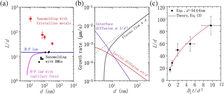
PHYSICAL REVIEW LETTERS 122, 036101 (2019)
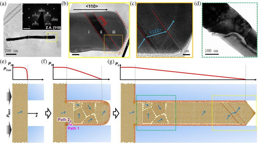
FIG. 3. Atomic growth mechanism of thermomechanical nanomolding with crystalline metals. (a)–(c). TEM images from a diameter
of 50 nm Au nanorod fabricated by TMNM. (a) A bright field image of an Au nanorod. (Inset) Its corresponding selected area electron
diffraction pattern reveals the growth direction as [110]. The scale bar is 0.41=Å. (b),(c) Enlarged images of the tip region [(b) and (c) are
captured from yellow and orange rectangles in (a) and (b), respectively]. Twins are revealed with twin planes of f111g close to the tip,
and f111g facets at the tip. f111g planes are marked by red-dashed lines in (b) and (c). h112i directions are indicated as blue arrows in
(c) to highlight mirrorlike symmetrical characteristics on the twin boundaries. Twins can be generated to release local energy or misfit
upon growing, which is commonly observed in face-centered-cubic Au. (d) A TEM image from a ∼100 nm Au nanorod showing
multiple grains with different crystallographic orientations at the root of the nanorod. (e)–(g) Schematics of TMNM with CMs indicating
atomistic processes as a sequence of growth of a metal nanorod and corresponding pressure profiles along its axis. Blue arrows represent
h112i direction vectors. (e) A feedstock metal (here for fcc) is positioned on the mold at the molding temperature, and a molding
pressure is applied. (f) The applied pressure and temperature result in diffusion down the pressure gradient, which causes a vacancy
gradient. As the initial orientation of the feedstock metal consists of multiple and randomly oriented grains, growth originally starts
along a nonpreferred orientation. This causes nucleation of new grains which progress toward a more preferred orientation (for fcc closer
to [110]). There are two possible and size dependent diffusion mechanisms: (i) interface diffusion along the mold-metal interface (path
1) and (ii) lattice diffusion through the rod (path 2). (g) A rod at a later stage of molding which contains small crystals on the root, a long
region of a perfect single crystal which can exceed L=d > 100, and twins and faceted edges at the tip.
scales than experimentally observed without an overall Equation (2) reveals that both diffusion based mecha-
driving force for diffusion. However, as the pressure varies nisms result in a growth rate inversely proportional to d.
along the forming nanorod (see Fig. 3), so does the vacancy Such behavior is qualitatively consistent with our exper-
concentration. Hence, diffusion into the mold cavity is not a imental observations (Figs. 1(c) and 2(a), and Fig. S1 of the
random diffusion process but is driven by a gradient of Supplemental Material [17]). To compare diffusion based
vacancy concentration. Considering that the diffusion of an growth (lattice and interface) of metallic nanorods with the
atom can go through either the lattice or the mold-CM viscous flow based nanomolding of BMGs, the growth
interface [38,39], we separately calculate the growth rates rates for typical nanomolding of Pt-BMG and diffusion
for lattice diffusion and interface diffusion by assuming that based growth of Au at 500 °C are calculated [Fig. 2(b)]. The
vacancy concentration varies only along the axis of the diffusion controlled mechanism are qualitatively in agree-
nanorod (1D model; see the Supplemental Material [17]): ment with our experimental data, whereas the viscous flow
behavior is not. When assuming that the interface diffu-
sivity is 10 times faster than the lattice diffusivity, below
pΩDL 2δ 2 1 1 d ∼ 10 nm, interface controlled growth would be the more
u_ L ¼ 1− ∝ forδ ≪ d;
kTλ d d d efficient mechanism. However, as the interface diffusivity
_ I 4pΩδDI
4Q 2δ 1 1 is unknown and will be highly sensitive to mold-CM
u_ I ¼ 2 ¼ 1− ∝ for δ ≪ d; ð2Þ combinations, the crossover of interface diffusion domi-
πd kTλ d d2 d2
nated growth at ∼10 nm has a large uncertainty, as it is only
estimated and may vary significantly.
where Ω ¼ 4πr30 =3 is the atomic volume, r0 the atomic To quantitatively compare the diffusion based mecha-
radius, δ the interface thickness, DL the lattice diffusion nism with the experimentally determined aspect ratio of
coefficient, and DI the interface diffusion coefficient. metallic nanorods, we add both diffusion processes, as they
036101-3PHYSICAL REVIEW LETTERS 122, 036101 (2019)
can independently and simultaneously occur and integrate orientations, a change in orientation is generally required
Eq. (2) with respect to time, and we get to form the observed [110] nanorods. This occurs at the
sffiffiffiffiffiffiffiffiffiffiffiffiffiffiffiffiffiffiffiffiffiffiffiffiffiffiffiffiffiffiffiffiffiffiffiffiffiffiffiffiffiffiffiffiffiffiffiffiffiffiffiffiffiffiffiffiffiffiffiffiffi entrance to the mold cavity, where often several small
2 ffi crystals with “rotating” orientations toward [110] can be
L L0 2pΩDL t DI δ
¼ þ 1þ4 for δ ≪ d: ð3Þ observed [Fig. 3(d) and Fig. S4 of the Supplemental
d d kTd2 DL d
Material [17] ]. This suggests that the originally growth
of nanorods follows the orientation of the feedstock crystal.
L0 is the depth of metal filling into the mold when the
As this orientation is generally not [110], a faster growing
loading force reaches its maximum value. Equation (3)
crystal with an orientation closer to or of [110] may
predicts L=d ∝ t1=2 . To test this prediction, we experimen-
nucleate, and eventually [110] oriented crystal forms and
tally varied the molding time while keeping all other
prevails to continue to grow into very high aspect-ratio
processing conditions constant (see the Supplemental
nanorods. During growth, particularly close to the tip or at
Material [17]). We found a good description of Eq. (3)
the branches, twins can be readily formed to maintain the
in the experimental data [Fig. 2(c)]. It is worth mentioning
preferred [110] direction with little energy cost, which
that ½∂ 2 ðL=dÞ=∂t2 < 0, indicating a decreasing growth
indicates that shear mechanism based twinning deforma-
rate with increasing molding time. Such a decrease in the
tion can also contribute to the growth of Au nanorods.
growth rate originates from a decreasing gradient between
However, the very few observed twins in the prepared
the pressure at the tip of the nanorod and the pressure above
metallic nanorods (Fig. 3 or Ref. [16]) indicate that the
the mold cavity, Δp ≈ p=L. Most importantly, the pre-
twinning is not the dominated deformation mechanism in
dictions of Eq. (3) agreeing well with the experimental data
TMNM with CMs.
reveal that the mechanism of TMNM with CMs is diffusion
One of the major findings of our work is that molding
dominated. However, it must be noted that the lattice
becomes easier with decreasing mold size, quantified by a
diffusion mechanism predicts a size-independent growth
decreasing function L=d with d. This scaling naturally
length while an interface diffusion mechanism results in a
results from the scaling of the underlying diffusion con-
growth length inversely proportional to the mold size
trolled mechanism. For lattice diffusion, Eq. (2) suggests
[Eq. (3)]. If we plot the experimental data in Fig. 2(a)
that L=d ∝ 1=d; whereas for interface diffusion L=d ∝
(red solid pentagons) as LðdÞ (Fig. S2 of the Supplemental
Material [17]), we find that the growth length of Au 1=d3=2 . Our data suggests, particularly for d > 10 nm, a
nanorods is approximately constant—however, with a predominant lattice diffusion dominated mechanism.
superimposed term. Such a term, which is proportional However, this may be superimposed by an interface dif-
to the mold size, can be attributed to dislocation motion as fusion mechanism, particularly for d < 10 nm. The effec-
the slip system become increasingly activated with increas- tiveness of the interface diffusion mechanism strongly
ing mold size under a high forming pressure of ∼800 MPa. depends on the mold material and moldable crystalline
To further identify the mechanism for TMNM with CMs metal, and hence it can dominate the transport mechanism.
and characterize the orientation of the grown nanorod, In that case, the additional 1=d3=2 (to the 1=d) originates
we used TEM (see the Supplemental Material [17]) from the increasing surface to volume ratio with decreasing
[Figs. 3(a)–3(d)]. We found for the considered Au nanorods d. Experimentally, fabricating the smallest nanofeatures by
that all are essentially single crystals growing along [110]. TMNM with CMs is limited by available molds. For the
Often, close to the tip, few twins are observed [Fig. 3(c), smallest mold size of 5 nm considered in our experiments,
HRTEM images at local regions (i)–(iii) are shown in we found that L=d follows the trend suggested by Eq. (3)
Fig. S3 of the Supplemental Material]. The preferred [Fig. 2(a)], and the aspect ratios of the molded Au nanowires
orientation of the Au nanorods along [110] during exper- arrays are as high as ∼340 [Fig. 2(a)].
imental growth may originate from the anisotropy of self- Besides the capability of TMNM with CMs to fabricate
diffusion in crystalline metals. As the f110g planes are the smallest-in-diameter nanorods, another demonstration of
loosest packed planes, diffusion occurs most rapidly along versatility requires study of the range of materials that can be
[110] (see, e.g., Ref. [40]). At the entry of the mold cavity, formed by TMNM. In opposition to most practical nano-
some small crystals can be found [Fig. 3(d); see also Fig. S4 fabrication techniques, TMNM should be possible with
of the Supplemental Material [17] ]. essentially all metals and alloys, as the underlying diffusion
Based on the TEM investigations [Figs. 3(a)–3(d)] and mechanism is present in all metals and alloys. To demon-
growth scaling and velocity observations (Fig. 2), we strate such versatility, we considered various metals, includ-
propose the following atomic-scale mechanism for ing metals with different crystal structures and alloys
TMNM with CMs [Figs. 3(e)–3(g)]: The pressure gradient ranging to the extreme case of high entropy alloys.
from entry to tip along the cavity depth results in a vacancy Specifically, we considered gold, nickel (fcc), vanadium
concentration gradient. Diffusion occurs predominately (bcc), iron (bcc), Ag75 Ge25 , Ni60 Ti40 , Cu34.7 Zn3.0 Sn62.3 ,
along this gradient. As the feedstock from which the PdCuNi, and PdCuNiPtRhIr [41] (Figs. 4(a)–4(i); see the
nanorods are molded comprises crystals with random Supplemental Material [17] for the casting of alloys).
036101-4PHYSICAL REVIEW LETTERS 122, 036101 (2019)
FIG. 4. Examples of fabricated nanorods arrays through TMNM with CMs. (a) Au nanorods of 5–13 nm in diameter, formed under a
pressure of ∼500 MPa at 500 °C for 100 s. (b) TMNM with Ni (fcc) at 600 MPa and at 600 °C for 240 s. (c) TMNM with V (bcc) at
437 MPa and at 650 °C for 100 s. (d) TMNM with Fe (bcc) at 400 MPa and at 600 °C for 240 s. (e) TMNM with Ni60 Ti40 at 650 °C, under
the forming pressure of 800 MPa for 180 s. (f),(g) TMNM with Ag75 Ge25 and Cu34.7 Zn3.0 Sn62.3 at 500 °C, loaded to ∼350 MPa under a
constant loading rate of 1.8 mm=min. (h) TMNM with PdCuNi at 695 °C, under the forming pressure of 800 MPa for 180 s. (i) TMNM
with high entropy alloy (PdCuNiPtRhIr) at 650 °C, under the forming pressure of ∼1000 MPa for 180 s.
For all considered metals and alloys, high-aspect-ratio [1] J. Schroers, T. M. Hodges, G. Kumar, H. Raman, A. J.
nanorods can be readily fabricated using TMNM with CMs. Barnes, Q. Pham, and T. A. Waniuk, Mater. Today 14, 14
In summary, we revealed the underlying mechanism (2011).
for thermomechanical nanomolding with crystalline met- [2] L. J. Guo, Adv. Mater. 19, 495 (2007).
[3] G. Kumar, H. X. Tang, and J. Schroers, Nature (London)
als as a diffusion controlled growth mechanism. Such a
457, 868 (2009).
mechanism results in single crystal molding of high-
[4] Z. Shao, M. Gopinadhan, G. Kumar, S. Mukherjee, Y. Liu,
aspect-ratio nanorod arrays and becomes easier with C. S. O’Hern, J. Schroers, and C. O. Osuji, Appl. Phys. Lett.
decreasing nanorod diameter. The presence of underlying 102, 221901 (2013).
diffusion mechanism in all metals and alloys suggests [5] P. Ruchhoeft et al., J. Vac. Sci. Technol. B 17, 2965
that TMNM with CMs is applicable to essentially all (1999).
metals and alloys. This is different from the vast majority [6] Y. N. Xia and G. M. Whitesides, Annu. Rev. Mater. Sci. 28,
of nanomolding methods, which are typically limited to 153 (1998).
specific materials and/or by the size and aspect-ratio [7] S. Y. Chou, P. R. Krauss, and P. J. Renstrom, Science 272,
ranges. Such versatility and practicality of thermome- 85 (1996).
chanical nanomolding with crystalline metals indicate a [8] H. D. Rowland, W. P. King, J. B. Pethica, and G. L. W.
period of rapid progress and novel exploration of metal Cross, Science 322, 720 (2008).
[9] M. Diez, P. Mela, V. Seshan, M. Möller, and M. C. Lensen,
based nanomaterials.
Small 5, 2756 (2009).
Z. L. and G. H. acknowledge the National Natural [10] S. S. Williams, M. J. Hampton, V. Gowrishankar, I. K. Ding,
Science Foundation of China (Grants No. 11602175, J. L. Templeton, E. T. Samulski, J. M. DeSimone, and M. D.
No. 11632009, and No. 11872284). Z. L. also acknowl- McGehee, Chem. Mater. 20, 5229 (2008).
[11] O. J. A. Schueller, G. M. Whitesides, J. A. Rogers, M.
edges the support from the “Thousand Youth Talents Plan”
Meier, and A. Dodabalapur, Appl. Opt. 38, 5799 (1999).
in China. S. S., N. L., and J. S. acknowledge the U.S.
[12] Y. Saotome and Z. A. I. Tao, MRS Online Proc. Libr. 554,
Department of Energy through the Office of Science, Basic 385 (1998).
Energy Sciences, Materials Science and Engineering [13] J. Schroers, Adv. Mater. 22, 1566 (2010).
Division (Grant No. DE SC0004889). [14] M. Colburn et al., Proc. SPIE 3676, 379 (1999).
[15] N. Li, W. Chen, and L. Liu, JOM 68, 1246 (2016).
[16] Z. Liu, Nat. Commun. 8, 14910 (2017).
[17] See Supplemental Material at http://link.aps.org/
*
Corresponding author. supplemental/10.1103/PhysRevLett.122.036101 for the de-
ze.liu@whu.edu.cn tails of Eq. (2), TMNM with Au and Fe, TEM characteri-
†
Corresponding author. zation, casting of alloys, supplementary Figs. s1–s4, and
jan.schroers@yale.edu supplementary Table s1.
036101-5PHYSICAL REVIEW LETTERS 122, 036101 (2019)
[18] K. Golden, B. Jerzy, and S. Jan, Nanotechnology 24, [29] X. Z. Liao, Y. H. Zhao, Y. T. Zhu, R. Z. Valiev, and D. V.
105301 (2013). Gunderov, J. Appl. Phys. 96, 636 (2004).
[19] Z. Liu and J. Schroers, Nanotechnology 26, 145301 (2015). [30] T. Zhu and J. Li, Prog. Mater. Sci. 55, 710 (2010).
[20] H. Gao, Y. Hu, Y. Xuan, J. Li, Y. Yang, R. V. Martinez, C. [31] Q.-J. Li and E. Ma, Mater. Res. Lett. 6, 283 (2018).
Li, J. Luo, M. Qi, and G. J. Cheng, Science 346, 1352 [32] X. Liu, Y. Shao, S. Y. Lu, and K. F. Yao, J. Polym. Sci. Part
(2014). B: Polym. Phys. 53, 463 (2015).
[21] E. Kim, Y. Xia, and G. M. Whitesides, Nature (London) [33] S. Ding, J. Kong, and J. Schroers, J. Appl. Phys. 110,
376, 581 (1995). 043508 (2011).
[22] R. D. Piner, J. Zhu, F. Xu, S. Hong, and C. A. Mirkin, [34] H. M. Chiu, G. Kumar, J. Blawzdziewicz, and J. Schroers,
Science 283, 661 (1999). Scr. Mater. 61, 28 (2009).
[23] P. Schall, I. Cohen, D. A. Weitz, and F. Spaepen, Nature [35] M. D. Uchic, D. M. Dimiduk, J. N. Florando, and W. D. Nix,
(London) 440, 319 (2006). Science 305, 986 (2004).
[24] V. Yamakov, D. Wolf, M. Salazar, S. R. Phillpot, and H. [36] F. F. Csikor, C. Motz, D. Weygand, M. Zaiser, and S.
Gleiter, Acta Mater. 49, 2713 (2001). Zapperi, Science 318, 251 (2007).
[25] Y. T. Zhu, X. Z. Liao, and X. L. Wu, Prog. Mater. Sci. 57, 1 [37] S. M. Makin, A. H. Rowe, and A. D. Leclaire, Proc. Phys.
(2012). Soc. London Sect. B 70, 545 (1957).
[26] X. L. Wu, X. Z. Liao, S. G. Srinivasan, F. Zhou, E. J. [38] Y. Oishi and W. D. Kingery, J. Chem. Phys. 33, 480 (1960).
Lavernia, R. Z. Valiev, and Y. T. Zhu, Phys. Rev. Lett. [39] C. Herring, J. Appl. Phys. 21, 437 (1950).
100, 095701 (2008). [40] W. C. Winegard, Acta Metall. 1, 230 (1953).
[27] Y. Wei, A. F. Bower, and H. Gao, J. Mech. Phys. Solids 54, [41] S. Sohn, Y. Liu, J. Liu, P. Gong, S. Prades-Rodel, A. Blatter,
2554 (2006). B. E. Scanley, C. C. Broadbridge, and J. Schroers, Scripta
[28] T. G. Langdon, Philos. Mag. 22, 689 (1970). Materialia 126, 29 (2017)
036101-6You can also read