DESIGN AND PARAMETRIC INVESTIGATIONS OF PERMANENT MAGNET ADHESION MECHANISM FOR ROBOTS CLIMBING ON REINFORCED CONCRETE WALLS - CLAWAR
←
→
Page content transcription
If your browser does not render page correctly, please read the page content below
CLAWAR 2020: 23rd International Conference on
Climbing and Walking Robots and the Support
Technologies for Mobile Machines,
Moscow, Russian Federation, 24-26 August 2020.
https://doi.org/10.13180/clawar.2020.24-26.08.45

     DESIGN AND PARAMETRIC INVESTIGATIONS OF PERMANENT
     MAGNET ADHESION MECHANISM FOR ROBOTS CLIMBING ON
                 REINFORCED CONCRETE WALLS

    VIJAYA GOPALA RAO M.V., ADITHYA BALACHANDRAN, SHEETAL P JADHAV,
 TULA SRIDATH, MANJU MOHAN, RM. KUPPAN CHETTY, D. DINAKARAN, M.M. RAMYA
            Centre For Automation and Robotics, School of Mechanical Sciences
           Hindustan Institute of Technology and Science, Chennai-603103, India
                           E-mail: kuppanc@hindustanuniv.ac.in
                                             www.hindustanuniv.ac.in

                         MOHAMMAD O. TOKHI AND TARIQ P. SATTAR
                 School of Engineering, London South Bank University, United Kingdom

    Wall Climbing Robots (WCRs) have found extensive applications in the past decade in numerous
    engineering fields, however, the design of efficient adhesion mechanism for robots climbing on concrete
    surfaces remains a challenge and attracts research attention. This paper proposes various designs of magnetic
    adhesion mechanism for concrete surfaces and investigates the adhesion force and payload capacities each
    design would accommodate for wall climbing robot applications. Permanent magnet is used as the magnetic
    adhesion mechanism and a yoke structure helps in holding the magnets and influences the adhesion
    characteristics of the mechanism. The effect of various structural designs of adhesion mechanisms on the
    adhesion force and payload capacity on the concrete surface is studied in this work. The adhesion forces
    against the different standoff distances which comprise the gap between the magnet and the concrete surface
    are also investigated therein. The results show that the developed adhesion mechanism can be applied for
    concrete walls generating the required adhesion forces and providing a better insight in choosing the best
    configuration, number of magnets and standoff distances for the design of adhesion mechanism against the
    required payload of WCR.

    Keywords: Adhesion mechanism; Wall climbing robot; Permanent magnets; Neodymium; magnetic.

1. Introduction
The growth in civilization and the thirst of human to urbanize his standard of living has led to
the construction of luxurious and sky-high tall buildings. But, with the increased number of
buildings and the advancements in architectural designs, the responsibility for humans to
provide regular maintenance and inspections of these buildings has also increased in order to
sustain the beauty of the buildings. In the earlier day’s inspection of cracks or defects on the
wall columns, dam structures, high-rise buildings, etc. were a matter of high risk, as human need
to climb and inspect the structures. Although, the availability of equipment for enabling a person
to perform inspection on the buildings is abundant, the risk factors could not be reduced as
humans are prone to having panic attacks or vertigo sensations or other unforeseen effects which
could harm or kill a person during climbing the buildings or structures for
inspection/maintenance works. Thanks to technological developments that now humans
directly/physically need not be involved in the inspection/maintenance works of the buildings
as gadgets like drones and wall climbing robots are available for inspection. The usage of
robotics for the process automation task such as automation of inspection has not only reduced
the risk factor involved in terms of human life but also according to Gartner’s hype cycle, the

© CLAWAR Association Ltd                               87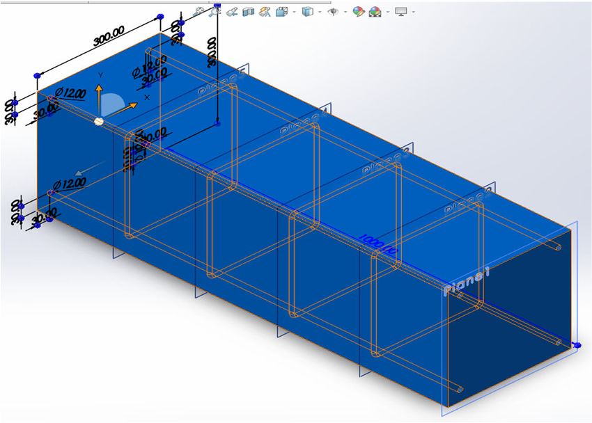
forecasted market revenue for robotics in the year 2019 was around $13 billion. Thus, helping
in terms of economic factors too.
    There are various adhesion mechanisms such as vacuum suction, magnetic attraction etc,
that can be employed for a robot to adhere to the surface of the wall. But the best and the most
reliable mechanism is the magnetic adhesion mechanism as this mechanism ensures proper hold
without losing the grip of the robot with respect to the surface it adheres. The proper design of
the magnets and their placements yield optimal results in terms of efficient adhering forces
between the wall surface and the robot. Various existing adhesion mechanisms and wall
climbing robots are analyzed such as the one by Yanagimura et al. [1], who propose a method
by which an MAV (Micro Air Vehicle) can travel in air without any involvement of propulsion
systems. For this to achieve, they designed and developed a magnetic adhesion system which
consists of a switch, a winch with servomotor and a rope/cable, a shaft with spring coiled around
and a magnet attached to the end of the shaft. Ward et.al, [2] have presented a design for the
electro permanent magnetic [EPM] adhesion device for optimal holding power of the magnets
on the metal surfaces with less weight of the adhesion device and simultaneously provide an
efficient failsafe solution to the robot involved in the climbing process. Berengueres et al. [3]
have proposed a distributed compliant device for holding/gripping purposes which is inspired
by a gecko foot mechanism.
    Lee et al. [4] have proposed a non-contact magnetic adhesion system which enables a robot
to move around the surface and, efficiently pass over obstacles on the surface, while holding the
robot’s position intact in any orientation. Li et al. [5] have proposed a new wall climbing robot
mechanism for easy wall-to-wall transition and for high payload requirements. They named
their robot as ‘combot’. Their robot can carry a payload of about 10 kg, and it is applicable to
heavy industrial applications. Sekhar et al. [6] have proposed a method to develop a low cost
and efficient wall climbing robot that can climb on almost all surfaces to ensure mechanical
stability. Howlader et al. [7, 8] have proposed a method for wall climbing robot by changing
the mechanical design parameters such as the magnet orientation, the distance between the
magnets, and yoke thickness using finite element analysis.
    Wile et al. [9] have proposed and created a miniaturized wall climbing robot with smart
robotic feet using suction pumps that can climb from floor to wall. It uses pic microcontroller
and 6-volt battery as the power source. Yehy et al. [10] have proposed a method to create wall
climbing robot using unipolar electro adhesion pad of aluminium and copper. The electrostatic
adhesion is produced by electrostatic field, but the force created is not great compared to the
magnetic field. Silva et al. [11] have proposed a model of a wall climbing robot using the
Bernoulli principle of suction vacuum pumps on concrete walls. Howlader et al. [8] have aimed
to develop a unique adhesion mechanism for wall climbing robot to automate the NDT
inspection of large critical reinforced concrete structures.
    Kanjanapan et al. [12] have proposed a model of a robot that can climb a surface and has the
ability to move back to the climbing surface when the robot starts to fall out of the wall.
Tovarnov et al. [13] have developed a model of a magnetic-tape locomotion mechanism for wall
climbing robot and have proposed mathematical model of the motion of a mobile robot on
vertical surface. Shen et al. [14] have described the design aspects of locomotion and magnetic
adhesion of permanent magnet and its embedded system. Wei et al. [15] proposed a lightweight
magnetic system to provide an optimum adhesion force and at required tire pressure to maintain
a specified air gap between the magnets and the surface for a wall climbing robot. Jose et al.
[16] have proposed the necessary conditions required for a wall climbing robot such as the
locomotion and adhesion techniques. Nansai et al.[17] have discussed various requirements for
cleaning wall climbing robot and categorized into 6 classes based on the adhesion mechanism.

                                               88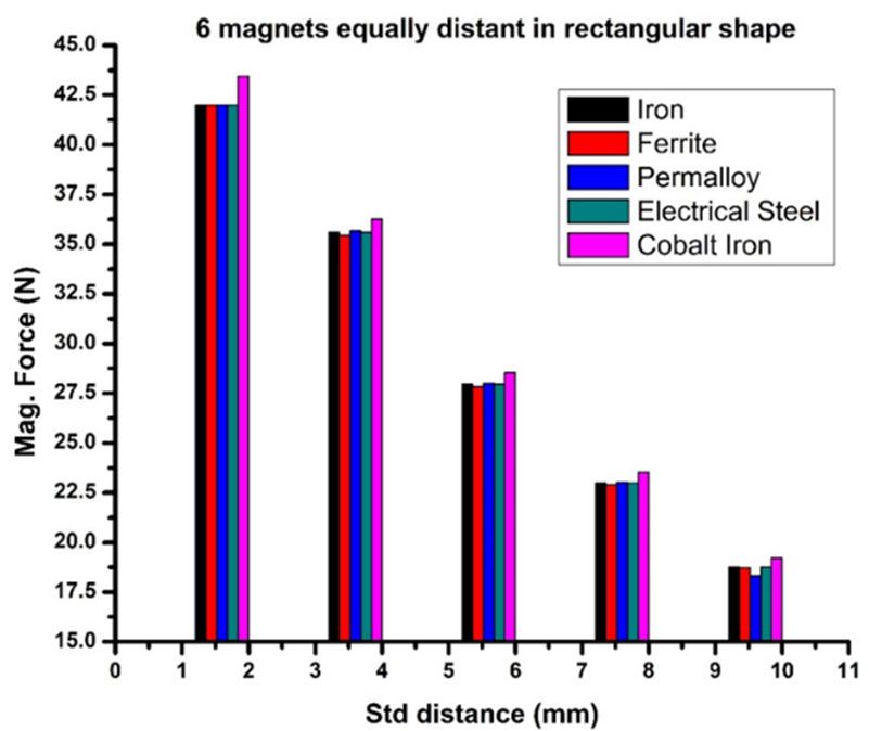
Sattar et al. [18] have proposed different methods to optimize the magnetic adhesion for ferrous
surface. Hussain et al. [19] have designed a robot framework for magnetic adhesion for
ferromagnetic surface using ANSYS FEM software for an efficient design.
      Based on the literature survey of the above papers, it is understood that wall climbing
robots, or the adhesion mechanisms used for enabling the robot to adhere the wall surface are
not stable enough to attract a concrete wall column. Also, the magnetic adhesion methods used
are only useful for adhering the robot to ferromagnetic surfaces or metal bodies. Therefore, this
research focuses on addressing the above stated issues and thus designing magnetic adhesion
mechanisms for attracting concrete wall columns by attracting the steel rebars inside the
concrete wall column. The work focuses more on the properties of the magnet and studies how
their orientation can influence the magnetic attraction. The N52 grade magnet is chosen as it is
the highest grade of magnet available in the market and has high penetrating magnetic flux
which caters for the intended purpose.

2. Materials and Methodology
The work presented in this paper focuses on the magnetic adhesion and the payload capacity of
a magnetic adhesion mechanism for various adhesion designs. The three-dimensional models of
the adhesion mechanisms and the concrete wall column are developed using SOLIDWORKS
CAD software. The simulation studies are carried out using ANSYS MAXWELL 3D software.

2.1 Materials Used
The materials used in the simulations comprise concrete wall column, neodymium permanent
magnets (NdFeB), and yoke (Electric Steel, Perm Alloy, Iron, Ferrite, Cobalt Iron). The concrete
wall column comprises of steel rebars, which are enclosed in a cement concrete structure with
adequate plastering. Although, there is a variation in the distance between the internal steel rebar
and the external concrete covering, for this work, the distance between the steel rebar and the
concrete covering inclusive of plastering is 30 mm. The properties of the steel rebar used for the
simulation are presented in Table 1.
                                      Table 1: Properties of steel rebar
                                 Properties                                 Value
                             Bulk conductivity                        2000000 siemens/m
                             Young’s modulus                            2×10¹⁰ N/m2
                               Poisson’s ratio                              0.25
                   Relative permeability of steel rebar(µr)                 1500

    The type of permanent magnet used in this work is NdFe52 (Neodymium Ferrous Boron).
This magnet is made of an alloy which primarily consists of Neodymium, Boron, and Iron.
Compared to other permanent magnets available such as Alnico, Ferrite and Samarium cobalt,
the neodymium magnets are the most powerful magnets. These magnets are available in various
sizes and shapes. Different size of magnets would also influence the payload capacity. The
properties of the N52 magnet are presented in Table 2. Adding yolk to the design of the adhesion
mechanism increases the magnetic flux, therefore influencing the payload capacity. This is due
to the magnetic coupling of the yolk with magnets. Optimizing the arrangement of the magnets
with the help of yoke would also influence the payload capacity. The material used for the yoke
should be highly permeable in nature in order to aid in increasing the magnetic flux density. The
derivatives of iron such as electrical steel, cobalt iron, perm alloy, iron and ferrite are found to
be highly permeable and are considered as yoke materials for this study. Table 3 presents the
properties of electrical steel, perm alloy, iron, ferrite, and cobalt iron, respectively.

                                                     89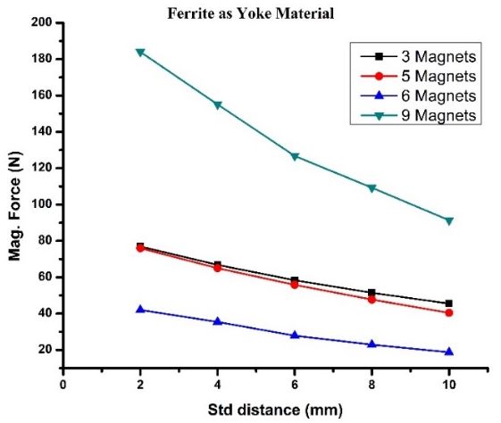
Table 2. Properties of NdFe52 permanent magnet
                                    Properties                                 Value
                         Magnetic induction intensity Br(T)                     1.31
                            Coercive force Hcb (KA/m)                              915
                         Intrinsic coercive force Hci (KA/m)                       955
                     Magnetic energy product HB (KJ/m3)                            318
                             Relative permeability (µr)                     1.068 – 1.113
                         Relative permeability of yoke (µr)                     5000
              Relative permeability of steel concrete surface (µr)                  1
                    Relative permeability of steel rebar(µr)                    1500

                                   Table 3 Properties of yoke materials in ANSYS
         Properties              Electric Steel   Perm-alloy         Iron           Ferrite    Cobalt Iron
    Relative permeability            4000            9000            5000            1000         1800
   Young’s modulus (GPa)              190             113            195                 119      230
       Poisson’s ratio                0.24            0.25           0.28                0.2      0.28

3. Simulation Studies

3.1 3D model of the adhesion mechanism and the concrete wall column
The development of 3D models for the adhesion mechanisms and the concrete wall column is
carried out using SOLIDWORKS software. The following steps are followed:
a) Problem definition: The problem begins with specifying the dimensions, the face/axis of the
    2D drawing being made, the required 3D extrude/cut to be performed, and finally, saving
    the file in STEP format for the simulations to be carried out in ANSYS MAXWELL 3D
    software.
b) Drawing the model: All the dimensions are set in millimeter (mm). The model of the
    adhesion mechanism/concrete wall column begins by selecting the face/view
    (Top/Side/Front Views) on which the blueprint of the 3D model is to be made.
c) Performing Extrude/Cut Operations: After the blueprints of the necessary 3D models of the
    adhesion mechanism, the concrete wall column is made. the specific entities such as the
    magnet, internal steel rebars, external concrete, square brackets and the yoke material are
    either extruded/intruded/cut as per the necessary requirements and dimensions. The concrete
    column is of cross section 300 mm. These measurements for the concrete column are
    considered as per standards followed in general constructions.
d) Saving File and Exporting: The developed 3D models are assembled using the “Align
    Object” tool as shown in Figures 1 and 2. The adhesion mechanism and the concrete wall
    column are attached to each other in a similar way as stated above, and this is depicted in
    Figure 3. The assembled files are saved with “.step” extension. The STEP extension is
    required as SOLIDWORKS is a proprietary software and has “.sldprt”/“.sldasm” extension.
    In order to export the developed 3D model to ANSYS MAXWELL 3D for further simulation
    the “.step” extension acts as an aid to bridge the gap between the two proprietary softwares
    i.e., “SOLIDWORKS” and “ANSYS MAXWELL 3D”.

                                                          90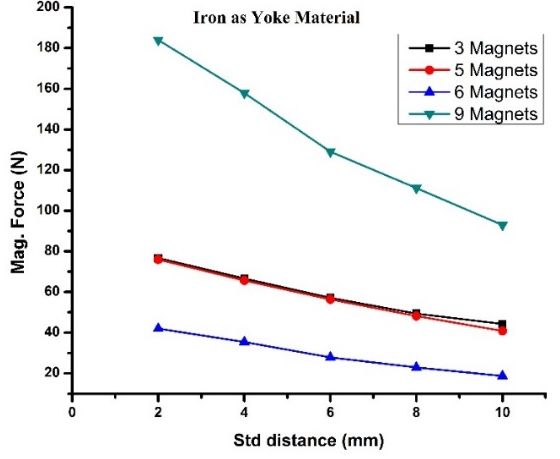
3.2. Simulation Using ANSYS MAXWELL 3D
ANSYS Maxwell 3D was used to find the adhesion force on the steel rebars. The focus is to
demonstrate the forces acting on the internal steel rebar and payload the magnets can carry, and
this software has the features necessary for this work. ANSYS has a built-in library so that the
required materials for the magnets, yoke (electric steel, perm alloy, iron, ferrite and cobalt iron),
wall column, and steel rebars could be defined in the software. In order to simulate the 3D
model, a specific space must be defined and hence a boundary is created around the 3D model.
The material for the boundary enclosure is selected as air (as air is the natural media between
the magnets and the concrete wall column). The following simulations are performed in ANSYS
MAXWELL 3D.
a) 5 Magnets of various dimensions in X shape yoke structure
The ‘X’ shape yoke configuration as shown in Figure 1 was simulated with various sizes of
magnet with 13 mm thickness. The distances between the concrete wall and the magnets are
considered as 2 mm, 4 mm, 6 mm, and 10 mm. The yoke thickness is assigned as 10 mm. The
simulations are performed on the X-shaped yoke and rectangular shaped yoke by varying the
dimensions of the magnets and varying the number of magnets and keeping the yoke material
as iron and assigning the distance between the wall and the magnets as 2mm constant. These
results are tabulated in Table 4. This proves that increase in magnet size can increase the overall
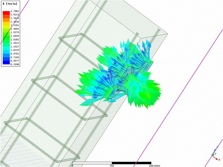
magnetic force/payload capacity. Figure 3 depict the ANSYS simulation environment with the
respective magnetic flux lines passing through the steel rebars.
Figure1. ‘X’ shaped yoke with magnets of different thicknesses using SOLIDWORKS
Figure 2. Concrete Cement block with square brackets
91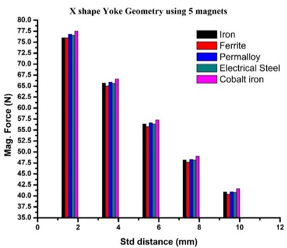
Figure 3. Magnetic flux line generated using ANSYS simulation
Table 4. Results for NdFe52 magnet with varying dimensions.
Magnets Length, Yoke Number of Yoke shape Distance Force
width, material Magnets from the (N)
thickness in concrete wall
(mm) in (mm)
Ndfe52 30, 30, 13 Iron 5 X shape 2 3
Ndfe52 40, 40, 13 Iron 5 X shape 2 8.33
Ndfe52 50, 50, 13 Iron 5 X shape 2 18.56
Ndfe52 50, 50, 13 Iron 4 Rectangle 2 31.40
According to Table 4, the magnet of the size 50 mm 50 mm 13 mm of rectangular yoke
shape has the highest magnet adhesion force among the rest. This proves that increase in the
magnet size can increase the overall magnetic force.
b) 3 and 6 magnets at equal distances in rectangular shape yoke
The 3-magnet configuration consists of magnets of length and width 50 mm and depth 13 mm.
In this case, the yoke material has been assigned as ferrite and iron, the dimensions of magnets
are kept constant, instead the distance is varied between the wall column and the magnets as in
[18-19]. The simulation results for the adhesion forces at various standoff distance for different
yoke materials is shown in Figures 4 (a) and (b). From the results it is understood that an increase
in the number of magnets would increase the adhesion force at the respective standoff distances
Similarly, the simulations are carried out for 6 magnet configurations placed at
equidistance as in [18-19]. Different yolk materials were assigned such as iron, ferrite, electric
steel, perm alloy and cobalt iron and checked whether the yolk material can improve the payload
capacity. In this simulation the distances between the wall column and magnets i.e. standoff
distance are also varied. Figure 5 depict the simulations results for the configurations obtained.
It could be observed that, the 6-magnet configuration provides less adhesion force as compared
to other configurations as observed in Figure 4. This is because of the discrepancy/non-
compliancy between the placement and alignment of the rectangular adhesion mechanism and
the steel rebars inside the concrete wall column.
92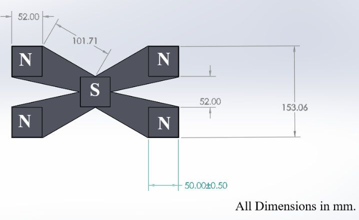
(a)                                                     (b)
  Figure 4 (a). Comparison between different yoke configuration using iron as a yoke material (b). ferrite as a yoke
                                                     material

     Figure 5. Comparison between different of adhesion force against the standoff distance for different yoke
configuration and yoke material, respectively. (a) for X- shape with 5 magnets (b) Rectangular shape with 6 magnets

     Figure 5 depicts the values of payload capacities obtained while using different yoke
materials and various standoff distances such as 2 mm, 4 mm, 6 mm, and 10 mm. It is evident
from Figure 5, irrespective of the materials, adhesion mechanism yields a maximum adhesive
force when the standoff distance i.e. the distance between the wall and the adhesion mechanism
of the WCR is at minimum level. For all the yoke materials, the maximum adhesive force
obtained is when standoff distance is at 2 mm. Thus, The results obtained through this work,
shows that the developed adhesion mechanism can be applied for concrete walls to generate the
required adhesion forces and provide a better insight in choosing the best configuration, number
of magnets and standoff distances for the design of adhesion mechanism against the required
payload of WCR.

4. Conclusion
In this study, an adhesion mechanism using permanent magnets has been developed for robots
climbing on reinforced concrete walls. The magnetic flux density describing the payload
capacity is visualized and analyzed using the simulations. The effect of various structural
designs of adhesion mechanisms on the adhesion force and payload capacity on the concrete
surface reinforced with metal rods is also studied in this work. The significance of yoke design,
yoke material selection and size of the magnet and the vital role they play in determining the

                                                         93
magnetic force/payload capacity is also explored. Through this research work, it is understood
that out of all adhesion mechanisms, the “X-Shaped” yoke provides an optimum payload hold
of 7.6 kg with almost any of the specified yoke material used and the specified magnet size.
During the study, out of all the composites of iron mentioned above, ferrite/iron material is most
commonly available in the market and is economically a feasible option compared to other
composites of ferrite/iron. Although, the ferrite material is heavier in terms of weight, the
specified “X-Shape” design helps in removing the extra bulk out of the total material and also
would help to yield optimum result and efficiency in terms of overall weight consideration when
this magnetic adhesion mechanism is used as part of a wall climbing robot development.
Moreover, based on the payload requirements, the required number of magnets can be chosen
for the adhesion mechanism. This leaves space for further investigation and the methodology
used in this paper could be extended to build a wall climbing robot with magnetic adhesion
mechanism.
Acknowledgments
Authors would like to thank the Royal Academy of Engineering, UK for supporting this research
work under Industry-Academia Partnership Programme, Newton funding, the project numbered
- IAPP18-19\27
References
1. K. Yanagimura, K. Ohno, Y. Okada, E. Takeuchi and S. Tadokoro S. IEEE Int. Conf. on
Robotics and Automation (ICRA), 6250 (2014)
2. P. Ward and D. Liu. IEEE Int. Conf. on Robotics and Biomimetics (ROBIO), 217 (2012)
3. J. Berengueres, K. Tadakuma, T. Kamoi and R. Kratz. Int. Conf. on Robotics and
Automation (ICRA), 1256 (2007)
4. G. Lee, G. Wu, J. Kim and T. Seo. Robotics and Autonomous Systems. 60 (10), 1308 (2012)
5. J. Li, X. Gao, N. Fan, K. Li and Z. Jiang. Int. Conf. on Mechatronics and Automation.
(2009)
6. S.R. Aravind, A. Mary, N.R. Sanju, G.R. Akhil, S. Vijitha and B. Gauri. 4th Int. Conf. on
Intelligent Systems, Modelling and Simulation, (2013)
7. M.O. F Howlader. Development of a Wall Climbing Robot and Ground Penetrating Radar
System for Non-Destructive Testing of Vertical Safety Critical Concrete Structures. (2016).
8. M.O.F. Howlader and T. Sattar. Int. J. of Adv. Comp. Sc. and App. 6(8), 8 (2015)
9. G. Wile, D. M. Aslam. Int. Conf. on Cybern. and Inf. Technol., Syst., and Appl. (CITSA).
87 (2007)
10. M.I. Yehya, H. Salman, W. Ahmad, J. Mirza and H. Abdalla. Int. J. of Robotics and
Mechatronics, 2(1), 1 (2016)
11. M.F. Silva, S.B. Ramiro, and A.L.C. Oliveira. J. of Robotics. 906545, (2012)
12. S. Kanjanapan, M. Pruttapon and S Konlayut. IEEE Int. Conf. on Robotics and Biomimetics
(ROBIO). (2017)
13. M.S. Tovarnov and N.V. Bykov. J. of Mach. Man. and Reliab. 48(3), 250 (2019)
14. W. Shen, J. Gu and Y. Shen. IEEE Int. Conf. Mechatronics and Automation. (2005)
15. S. Wei, J. Hongjian, W. Tao, J. Daxiong and Z. Shiqiang. Adv. in Mech. Engg. 10(7), (2018)
16. J. Jose, D. Dinakaran, M.M. Ramya and D.G. Harris. Int. J. of Mech., and Prod. Engg.
Research and Development. 8(6), 59 (2018)
17. S. Nansai and R. Mohan. Robotics. 5(3), 14 (2016)
18. T. Sattar, H. Salman and E. Salinas. Int. Conf. on CAD/CAM, Robotics and Factories of the
Future. (2011)
19. S. Hussain, T.P. Sattar and E. Salinas. Int. J. of Intel. Sys. Tech. and Appl. 11(1-2), 102
(2012)
94You can also read