Characterization of Compliant Parallelogram Links for 3D-Printed Delta Manipulators
←
→
Page content transcription
If your browser does not render page correctly, please read the page content below
Characterization of Compliant Parallelogram
Links for 3D-Printed Delta Manipulators

Pragna Mannam, Oliver Kroemer, and F. Zeynep Temel

Abstract We design a compliant delta manipulator using 3D-printing and soft
materials. Our design is different from the traditionally rigid delta robots as it
is more accessible through low-cost 3D-printing, and can interact safely with its
surroundings due to compliance. This work focuses on parallelogram links which
are a key component of the delta robot design. We characterize these links over twelve
dimensional parameters, such as beam and hinge thickness, and two material stiffness
settings by displacing them, and observing the resulting forces and rotation angles.
The parallelogram links are then integrated into a delta robot structure to test for delta
mechanism behavior, which keeps the end-effector parallel to the base of the robot.
We observed that using compliant hinges resulted in near-delta behavior, laying the
groundwork for fabricating and utilizing 3D-printed compliant delta manipulators.

1 Introduction

Personal care robots operating in homes require dexterous and compliant manip-
ulators to ensure that interactions with human and objects are performed reliably
and safely. Delta robots, Figure 1(a), are ideal for these applications due to their
low-inertia and high-precision [1]. The dexterity and precision of these robots en-
able them to manipulate objects in unstructured home environments. However, most
delta robots are made from rigid materials [2] which precludes them from inter-
acting safely with humans. The compliance of soft materials, on the other hand,
can allow them to conform to objects, exhibit physical robustness, and execute safe
human interactions [4]. Furthermore, 3D-printing delta robots using soft materials
reduces fabrication costs and makes them accessible to a wider community. This
paper presents the process of designing the first 3D-printable compliant delta robot
using soft materials. We characterize parallelograms, an integral component of the

Carnegie Mellon University, Pittsburgh PA 15213, USA,
e-mail: {pmannam, okroemer, ztemel}@andrew.cmu.edu
2 P. Mannam, O. Kroemer, and F. Z. Temel Fig. 1 (a) A delta robot with each arm consisting of a rigid portion and a flexible parallelogram with living hinges that transfers motion from motors at base to end-effector. (b) Ideal behavior of displaced tail of the parallelogram in characterization experiments testing different hinge and beam thicknesses and materials. delta robot, with varying dimensional parameters and materials to study their be- havior as part of a delta mechanism. More specifically, we focus on parallelogram hinge and beam thicknesses, and material stiffness. These design choices can then be leveraged to achieve desired end-effector behaviors of 3D-printed delta robots composed of compliant parallelogram links. Printing compliant delta robots requires a departure from the classical delta de- sign due to the use of soft materials, especially with respect to the joints. Rigid universal joints are replaced by two types of living hinges1, one in the compliant parallelogram links of the delta robot and the other between the end-effector and the parallelogram links, as seen in Figure 1(a). Properties inherent to soft materials like bending and hysteresis can alter the delta mechanism behavior. As shown in Figure 1(a), we expect the end-effector (or platform) of the delta robot to always stay parallel to its base as seen in the upright position; however, this orientation is not guaranteed in all configurations when using compliant materials. This deviation from the ideal kinematic behavior can be measured by the end-effector rotation with respect to the base across the robot configuration space. In this work, we study the characteristics of centimeter-scaled compliant parallelograms with 12 varied combinations of hinge and beam thicknesses, and 2 materials by displacing them incrementally and ob- serving the force required and resulting rotation of the parallelogram tail, as shown in Figure 1(b). Subsequently, we evaluate these parallelograms by integrating them into the delta robot structure and measuring the end-effector rotation with respect to the base in specific configurations of the robot. These experiments allow us to infer the parameters of the compliant parallelogram link that achieve the ideal kinematic behavior, bringing us one step closer to the goal of creating a 3D-printed compliant delta manipulator. 1 A living hinge is an articulated joint created by locally reducing the width of the material to make it more compliant in that region.
Characterization of Compliant Parallelogram Links 3

2 Related Work

Compliant robots have been used in biomedical applications and are built on micro
or milli scale using flexure-based mechanisms. Manufacturing compliant robots on
such a small scale is difficult using traditional techniques and are typically built using
either Micro Electro Mechanical Systems (MEMS) [5, 7, 8], or Electro-Discharge
Machining (EDM) [6, 9, 10, 11]. These manufacturing techniques require sophisti-
cated tools that are not accessible to the wider community. An alternative approach
is to utilize origami-inspired self-folding robots [14, 15, 16] or laminate robot mech-
anisms [17, 5, 13]. Our work is closest to the millimeter-scaled Delta robot using
laminate structures [5]. Unlike the manual assembly required for laminate robot
mechanisms, we look to successful prototyping of compliant mechanisms using 3D-
printing [12]. Our goal is to create a low-cost compliant delta manipulator without
using complex manufacturing techniques by relying on 3D-printing.
 A popular alternative parallel manipulator is the 6-DOF Stewart platform [3] that
can translate and tilt the end-effector unlike the delta robot which only allows the
end-effector to translate parallel to the base. Both of these manipulators can move at
high speeds and accelerations with low-inertia because their relatively heavy motors
are stationary and at the base. Delta robots, unlike Stewart platforms, have simple
closed-form kinematic solutions [2]. The characteristics improve as the mechanisms
are scaled down, which is why delta robots like the mm-scaled delta (milliDelta)
can move with precision down to 5 micrometers in a 7mm3 workspace and lend
themselves to micromanipulation [5]. Previous mm-scaled delta robots required
multi-step processes or manual assembly which introduced irregularities in the final
platforms [5][13]. In contrast, we use 3D-printing to make repeatable and accessible
delta robots.

3 Approach

The parallelogram structure plays an integral role in the delta robot’s functionality [1].
The key components of the parallelogram are the beam and hinge thicknesses, as
labeled in Figure 1(b). Hence, we start with characterizing the parallelograms with
varying beam and hinge thicknesses, as well as two different materials, by record-
ing the effect on force and position when displacing the tail of the parallelogram
as shown in Figure 1(b). Subsequently, we study the compounding effects of three
parallelogram links in a delta robot structure on the resulting end-effector orienta-
tion. This enables us to model the mechanical properties of different materials and
dimensional parameters of the compliant parallelogram that result in motions close
to the idealized delta mechanism.
 We characterized and evaluated the parallelogram links over twelve combinations
of dimensional parameters: 3 beam thickness values of 2.5mm, 3.5mm and 4.5mm,
and hinge thickness values of 0.375mm, 0.5mm, 0.75mm, and 1mm to study de-
viations from the ideal delta kinematic model caused by different hinge and beam
4 P. Mannam, O. Kroemer, and F. Z. Temel

thicknesses. For our experiments, we used Ultimaker S5 3D-printer and filaments.
We chose the two most compliant Ultimaker filament materials which are best suited
to living hinge mechanisms, polypropelene (PP) and thermoplastic polyurethane
(TPU) 95A. For comparison, the tensile modulus is 220 MPa (using ISO 527) and
26 MPa (using ASTM D638) for PP and TPU respectively. Additionally, the flexural
strength is 13 MPa and 4.3 MPa (both measured using ISO 178) for PP and TPU
respectively. These values indicate that TPU is more compliant than PP, which is
beneficial for the living hinges while the stiffness of PP is useful to maintain rigidity
of the parallelogram beams.

3.1 Characterization of Parallelogram

The two parameters for characterization experiments were the parallelogram beam
and hinge thicknesses (Figure 1(b)). The remaining dimensions were fixed, such as
the length and depth of the beams which were 27mm and 4mm respectively, and the
length of the hinge was always 2mm. Compliant parallelograms were made from PP
and TPU while supporting and mounting materials were 3D-printed using rigid poly-
lactic acid (PLA) material. Characterization experiments involved mounting these
parallelograms vertically and using a linear actuator to push the parallelogram tails
in 5mm increments to measure the exerted force, and resulting displacement and
orientation change of the tails. We vertically mounted parallelograms to reduce the
effects of gravity in pulling the parallelogram out of plane. As shown in Figure 2(a),
an Actuonix L12-R Micro Linear Servo is mounted with a Transducer Techniques
GS0-150 load cell to measure the force required to displace the parallelogram tail.
For PP parallelograms with beam thickness of 4.5mm, we used the GS0-500 load
cell instead to measure the higher force values that were required to displace these
parallelograms. Three grey markers on the parallelogram are tracked as a rigid body
by an OptiTrack V120:Trio camera with submillimeter accuracy to record the po-
sition and orientation of the parallelogram tail. The load stem was lubricated to
overcome frictional effects when pushing the parallelogram. Force measurements
were recorded after a six minute delay to allow for stabilization of any creep (de-
formation) effect. Additionally, rotation data from the markers on the parallelogram
indicate if the tail of the parallelogram rotated out-of-plane or twisted in plane.
 Using the same reference axes as shown in Figure 2(a), we observe in-plane and
out-of-plane rotations of the parallelogram tail. The force applied by the actuator
causes the tail of the parallelogram to move in an arc in the plane of the parallelogram.
Under ideal conditions, the tail would remain parallel to the base. However, due to
non-ideal hinge and beam behaviors, the tail exhibits additional rotations within
the plane of movement, i.e., about the Z axis. Additionally, the restorative force
of the parallelogram (caused by gravity and joint stiffness) will push back against
the actuator. Misalignment between this restorative force and the actuator’s pushing
force can result in the parallelogram twisting (Y axis rotation) or bending out of
Characterization of Compliant Parallelogram Links 5
 4 1.5

 2.5mm beam 2.5mm beam
 Camera tracking
 (D markers 3.5mm beam 3.5mm beam
 4.5mm beam 4.5mm beam
 Compression load sensor 3 0.375mm hinge
 0.5mm hinge
 0.375mm hinge
 0.5mm hinge

 Force (Newtons)

 Force (Newtons)
 1
 0.75mm hinge 0.75mm hinge
 Linear actuator 1.0mm hinge 1.0mm hinge
 2

 Y 0.5

 X 1

 Z (B
 1 cm
 0 0
 0 5 10 15 20 0 5 10 15 20
 Displacement (mm) Displacement (mm)

 (a) (b) (c)

Fig. 2 (a) Parallelogram characterization experiment setup: linear actuator mounted with com-
pression load sensor to displace the tail of a PP parallelogram with beam thickness = 2.5mm and
hinge thickness = 0.375mm. (b) Force-displacement plots for PP and (c) TPU for varying beam
thicknesses (shown with shapes) and hinge thicknesses (shown with colors). Each marker represents
the mean across five repetitions of the experiment.

plane (X axis rotation). Thus, we only focus on the in-plane rotations to test whether
the parallelogram tail stays parallel to the mounted end of the parallelogram.

3.2 Evaluation of Delta Mechanism

Rotations of the compliant parallelogram links directly relate to the rotations of the
delta robot end-effector. Hence, using the same parallelograms tested in the charac-
terization experiments, we validated the results by integrating the parallelograms as
links in an actuated delta robot as shown in Figure 4. The parallelogram links have
an added living hinge on each side, oriented 90 degrees apart from the compliant
links’ revolute joint, to mimic one universal joint at each end of the beams as shown
in Figure 1(a). Three of these parallelograms are attached to a triangular end-effector
platform, all created with either PP or TPU throughout. Then, the compliant delta
tops are secured to 3D-printed rigid links made with Ultimaker Tough PLA (shown
in red in Figure 4) which are attached to servo motors.
 To measure the end-effector rotation with respect to the base at different config-
urations of the robot, we define two configurations for each of the arms, namely up
and down, that are separated by a 50 degrees offset. We consider two configurations
of the robot, one in which two arms are down and the other arm is up, and the other
in which two arms are up and the other arm is down. The three marker points on the
end-effector are used to calculate the end-effector plane and normal axis. The normal
axis is computed at each position of the delta robot, such that the angle between the
normal vector and a reference base normal is used to compute the rotation of the
end-effector with respect to the base.
6 P. Mannam, O. Kroemer, and F. Z. Temel

Fig. 3 Characterization experiment results for Z rotation angles (in degrees) of PP and TPU
parallelograms at the largest displacement (20mm). The mean and standard deviation shown as
error bars are taken over five repetitions of the experiment. The most compliant hinges (0.375mm)
and least compliant hinges (1.0mm) are grouped together, and the colors denote different beam
thicknesses of 2.5, 3.5, and 4.5 mm.

4 Experimental Results

4.1 Characterization experiments

We tested parallelograms of varying hinge thickness (0.375, 0.5, 0.75, and 1mm)
with beam thickness of 2.5mm, 3.5mm, and 4.5mm. The force values at the end
of each 5mm increment push until 20mm for both PP and TPU, averaged over five
repetitions, are shown in Figure 2(b) and (c) respectively. The circle, triangle, and
square markers denote 2.5mm, 3.5mm, and 4.5mm respectively, and each color
denotes a difference hinge thickness between 0.375 and 1 mm. Five repetitions were
executed for a given set of dimensional parameters and material on a newly printed
parallelogram, resulting in a total of 120 characterization experiments. There is a
clear trend for both materials where displacing the parallelogram by a larger distance
takes more force. Overall, PP parallelograms require more force to displace than ones
made from TPU, needing almost 4N versus close to 1.5N for the stiffest (thickest)
hinges at 20mm displacement.
 Using OptiTrack markers, Z rotation angles of the parallelogram tail were recorded
after displacements of 5mm increments up to 20mm. In Figure 3, the mean and
standard deviation for Z rotation angles are shown for both PP and TPU at the
largest (20mm) displacement. For the same beam thickness, increasing the hinge
thickness tends to result in larger Z rotations across both materials implying that
in-plane rotations are smaller for thinner hinges. We can also observe that for a given
beam and hinge thickness, TPU results in larger in-plane rotations when compared
to PP. This can be attributed to higher compliance of TPU when compared to PP.
Characterization of Compliant Parallelogram Links 7

 (Beam th., Hinge th.) X-rotation Y-rotation Z-rotation 2 up, 1 down 2 down, 1 up

 PP (2.5, 0.375) 2.31 2.11 2.28 0.85 1.90 0.41 6.27 1.68 5.65 1.66
 PP (3.5, 0.375) 1.03 0.38 2.35 1.85 2.78 0.74 8.12 3.80 5.87 1.49
 PP (4.5, 0.375) 2.08 0.84 4.68 1.56 1.84 0.12 8.75 2.61 6.15 3.83
 PP (2.5, 1.0) 1.20 1.11 3.10 2.65 3.90 0.64 20.08 5.91 17.01 3.31
 PP (3.5, 1.0) 1.04 0.38 1.20 0.57 5.26 0.14 15.23 0.86 13.22 1.69
 PP (4.5, 1.0) 3.87 1.62 9.32 3.37 4.01 0.16 15.01 0.72 11.57 4.04
 TPU (2.5, 0.375) 2.26 1.39 2.06 1.70 2.97 0.61 7.84 3.51 7.69 2.23
 TPU (3.5, 0.375) 1.21 1.03 1.41 0.72 2.87 0.17 5.5 0.24 5.44 1.48
 TPU (4.5, 0.375) 1.06 1.42 1.60 0.95 2.58 0.30 4.72 1.42 5.00 2.09
 TPU (2.5, 1.0) 0.62 0.24 5.86 3.82 5.56 0.48 17.18 4.83 13.55 2.00
 TPU (3.5, 1.0) 0.73 0.59 2.03 1.83 5.63 0.45 18.54 5.95 15.35 4.36
 TPU (4.5, 1.0) 0.93 0.26 2.50 1.96 5.14 0.90 20.49 9.99 14.67 2.08

Table 1 Characterization experiment results for X, Y, and Z rotation of parallelograms at 20mm
displacement. The mean ( ) and standard deviation ( ) is taken over five repetitions of the experi-
ment. The last two columns consist of data from evaluation experiments integrating parallelograms
of varying beam and hinge thicknesses and calculating the rotation of end effector (in degrees).
The mean and standard deviation of three repetitions raising 2 arms and lowering one arm (2 up, 1
down) as well as lowering 2 arms and raising 1 arm (2 down, 1 up) by 50 degrees is listed in fourth
and fifth columns respectively.

Interestingly, for a fixed hinge thickness varying the beam thickness does not show
consistent behavior across materials and hinge thicknesses. We leave exploring the
reasons to future work.
 The X, Y, and Z rotation angles with mean and standard deviation at 20mm
displacement of the parallelogram can be found in the first three columns of Table 1.
As expected from our discussion in Section 3.1, X and Y rotations, corresponding to
out-of-plane rotations, have high standard deviations due to misaligned restorative
and actuator pushing forces. We have included these rotation values for completeness
in Table 1. We can conclude that for both PP and TPU materials, a hinge thickness of
0.375mm results in the least in-plane rotation. For beam thickness, the table indicates
that both 2.5mm and 4.5mm for PP material have small in-plane rotations. Similar
to Figure 3, we can infer that PP material achieves smaller mean in-plane rotation
when compared to TPU material across all settings which can be again attributed to
the difference in stiffness between the materials.
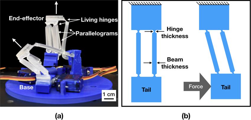
8 P. Mannam, O. Kroemer, and F. Z. Temel

Fig. 4 Evaluation experiment parallelograms with beam thickness 2.5mm and hinge thickness of
(a) 1mm and (b) 0.375mm are shown before and after lowering one arm (2 arms up, 1 down) by 50
degrees.

4.2 Evaluation Experiments

We evaluated the effects of integrating parallelograms from the characterization
experiments, TPU and PP parallelograms with the most and least compliant hinges
(0.375mm and 1.0mm), into full delta mechanisms. Specifically, we studied the
effect on the end-effector orientation, relative to the base, when it is moved towards
the edge of the configuration space, by lowering or raising each arm by 50 degrees,
as shown in Figure 4. Both configurations were repeated three times with each of
the three arms. We present the mean and standard deviation of the end-effector
rotation in Table 1 (last two columns.) For both PP and TPU materials, hinge
thickness of 0.375mm results in a smaller end-effector rotation when compared to
a hinge thickness of 1.0mm across all settings. This highlights the importance of
compliance in living hinges to achieve delta behavior that is closer to ideal. With
a thick hinge, parallelogram links are stiff and unable to maintain the end-effector
orientation to be parallel to the base. This is similar to the conclusion drawn from
our characterization experiments where we observed that smaller hinge thicknesses
are better for minimal in-plane rotations.
 Among parallelograms with hinge thickness of 0.375mm, a beam thickness of
2.5mm works best for PP while a beam thickness of 4.5mm works best for TPU. This
can be attributed to the stiffness of PP which requires thinner beam to be flexible
enough to maintain the end-effector orientation across different configurations. On
the other hand, TPU is more compliant and requires thicker beams to ensure that
the beams stay parallel to each other which is important to achieve an end-effector
orientation that is parallel to the base.
 The amount of permissible rotation is dependent on the application, but for
manipulating large objects (centimeter scale or larger) 7 degrees of rotation or less is
manageable. From a visual perspective as well, about 7 degrees of rotation in Figure
4(b) still demonstrates near-delta robot behavior.
Characterization of Compliant Parallelogram Links 9

5 Conclusion and Future Work

We tested 3D-printed parallelograms made with two materials of significantly vary-
ing stiffness, PP and TPU. The characterization experiments presented in Section 4.1
studied the effects of displacing the parallelogram tail. Due to the large variation in
amount of force required for each of the parallelogram dimensions and materials, the
force profile can be chosen for a specific application. For example, a delta robot that
is interacting with humans for applications like assisted feeding is expected to be
more compliant and therefore require less force to be displaced. Thus, we can tailor
the parameters and material of the parallelogram links to the desired application
using the force profile. Our characterization experiments have also indicated that
more compliant hinges and PP material are better for achieving minimal in-plane
rotations. Our evaluation experiments in Section 4.2 also show that more compliant
hinges result in end-effector orientations that are closer to ideal delta behavior. In
addition, our evaluation experiments have also provided insight into the ideal beam
thickness for PP and TPU materials that result in minimal end-effector rotation.
 Working with soft materials is challenging as their properties change over time
and across repetitions. In order to control the 3D-printed delta for manipulation,
we will have to learn how to accommodate for the material properties and adapt
to changes. Our work is an initial step in this direction and the experiments show
the potential of a 3D-printed delta using soft materials. Future extensions of this
work involve manipulation tasks using opposing delta manipulators, arrays of delta
robots for distributed actuation platforms, and modeling compliant delta robots.
Modeling the delta robots also involves studying the error from rigid delta kinematic
models and how to compensate for the error using robust control and state estimation
techniques.

Acknowledgements We thank Avi Rudich, Anirudh Vemula, Ankit Bhatia, Tess Hellebrekers, and
Keene Chin for their assistance and support. The research presented in this work was funded by
National Science Foundation under Grant No. CMMI-2024794 as well as an Amazon Research
Award.

References

1. L. Rey and R. Clavel. The delta parallel robot. In Parallel Kinematic Machines, pages 401-417.
 Springer, 1999.
2. L. Tsai. Robot Analysis: The Mechanics of Serial and Parallel Manipulators. (John Wiley &
 Sons, 1999).
3. D. Stewart. A Platform with Six Degrees of Freedom. Proceedings of the Institution of Mechan-
 ical Engineers. 180.1 (1965): 371-386.
4. C. Laschi, B. Mazzolai, and M. Cianchetti. "Soft robotics: Technologies and systems pushing
 the boundaries of robot abilities." Science Robotics 1.1 (2016): eaah3690.
5. H. McClintock, F. Z. Temel, N. Doshi, J. Koh, and R. J. Wood. The millidelta: A high-bandwidth,
 high-precision, millimeter-scale delta robot. Sci. Robotics, 3(14), 2018.
10 P. Mannam, O. Kroemer, and F. Z. Temel

6. Y. Tian, et al. "Design and forward kinematics of the compliant micro-manipulator with lever
 mechanisms." Precision Engineering 33.4 (2009): 466-475.
7. N. P. Belfiore, and P. Simeone. "Inverse kinetostatic analysis of compliant four-bar linkages."
 Mechanism and Machine Theory 69 (2013): 350-372.
8. M. Balucani, et al. "The development of a MEMS/NEMS-based 3 DOF compliant micro robot."
 19th International Workshop on Robotics in Alpe-Adria-Danube Region (RAAD 2010). IEEE,
 2010.
9. U. Bhagat, et al. "Design and analysis of a novel flexure-based 3-DOF mechanism." Mechanism
 and Machine Theory 74 (2014): 173-187.
10. M. L. Culpepper, and G. Anderson. "Design of a low-cost nano-manipulator which utilizes a
 monolithic, spatial compliant mechanism." Precision engineering 28.4 (2004): 469-482.
11. B. J. Yi, et al. "Design and experiment of a 3-DOF parallel micromechanism utilizing flexure
 hinges." IEEE Transactions on robotics and automation 19.4 (2003): 604-612.
12. R. S. Pierre, N. Paul, and S. Bergbreiter. "3DFlex: A rapid prototyping approach for multi-
 material compliant mechanisms in millirobots." 2017 IEEE International Conference on
 Robotics and Automation (ICRA). IEEE, 2017.
13. J. E. Correa, et al. ’Laminated micro-machine: Design and fabrication of a flexure-based Delta
 robot.’ Journal of Manufacturing Processes 24(2016): 370-375.
14. A. Mehta, J. DelPreto, and D. Rus. "Integrated codesign of printable robots." Journal of
 Mechanisms and Robotics 7.2 (2015).
15. S. J. Kim, et al. "An origami-inspired, self-locking robotic arm that can be folded flat." Science
 Robotics 3.16 (2018).
16. B. Shin, et al. "Self-assembling sensors for printable machines." 2014 IEEE International
 Conference on Robotics and Automation (ICRA). IEEE, 2014.
17. J. Koh, et al. "A modular folded laminate robot capable of multi modal locomotion." Interna-
 tional Symposium on Experimental Robotics. Springer, Cham, 2016.
You can also read