A general form of capillary rise equation in micro grooves - Nature
←
→
Page content transcription
If your browser does not render page correctly, please read the page content below
www.nature.com/scientificreports
OPEN A general form of capillary rise
equation in micro‑grooves
Gholamreza Bamorovat Abadi* & Majid Bahrami
Micro-grooves are a crucial feature in many applications, such as microelectro-mechanical systems,
drug delivery, heat pipes, sorption systems, and microfluidic devices. Micro-grooves utilize capillary
action to deliver a liquid, with no need for an extra pumping device, which makes them unique
and desirable for numerous systems. Although the capillary action is well studied, all the available
equations for the capillary rise are case-specific and depend on the geometry of the groove, surface
properties, and the transport liquid. In this study, a unified non-dimensional model for capillary rise
is proposed that can accurately predict the capillary rise for any given groove geometry and condition
and only depends on two parameters: contact angle and characteristic length scale, defined as the
ratio of the liquid–vapor to the solid–liquid interface. The proposed model is compared against data
from the literature and can capture the experimental results with less than 10% relative difference.
The effect of the grooves’ height, width, and contact angle is investigated and reported. This study
can be used for a unified approach in designing heat pipes, capillary-assisted evaporators for sorption
systems, drug delivery micro-fluidic devices, etc.
List of symbols
A Area (m2)
D Depth (m)
F Force (N)
g Gravitational acceleration (m/s2)
h Capillary rise (m)
L Characteristic length scale (m)
Pw Wetting perimeter (m)
R Radius (m)
W Width (m)
α Inclination angle (°)
θ Contact angle (°)
ρ Density (kg/m3)
σ Surface tension (N/m)
Subscripts
sv Solid–vapor
sl Solid–liquid
lv Liquid–vapor
c Capillary
The self-driving flow of a liquid in a capillary micro-groove is an important feat of engineering with a wide range
of applications, from space applications due to microgravity to power electronics and heat pipes, to sorption
technology and capillary-assisted evaporators.
One main application of capillary action in micro-grooves is in heat pipes. These two-phase heat transfer
devices are a crucial part of any modern power electronic device. In fact, the capillary rise is one of the important
factors in designing heat pipes. Hopkins et al.1 experimented with flat miniature heat pipes to determine the
maximum heat flow rate and heat flux for different operating temperatures. They concluded that heat pipes with
deep and narrow capillary grooves produce the best results while most of their data showed that the heat flux
bottleneck of the evaporator was the capillarity limitation. Ma and Peterson2 performed a series of experiments
Laboratory for Alternative Energy Conversion (LAEC), School of Mechatronic Systems Engineering, Simon Fraser
University, Burnaby, BC V3T 0A3, Canada. *email: gbamorov@sfu.ca
Scientific Reports | (2020) 10:19709 | https://doi.org/10.1038/s41598-020-76682-2 1
Vol.:(0123456789)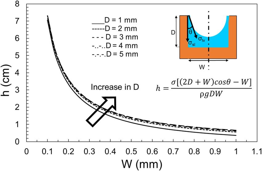
www.nature.com/scientificreports/
to determine the heat transport in triangular grooves, similar to those used in heat pipes, purely based on the
capillary rise limit. They reported the maximum capillary heat transport capacity and pure capillary limit of
methanol flowing in triangular grooves. Another example of capillary limit in heat pipes is3. They concluded that
a heat pipe’s performance is greatly dominated by the capillary limit. They established a mathematical model of
the capillary limit for a micro heat pipe with trapezium-grooved substrate.
Vapor chambers or flat heat pipes are of particular interest and are used extensively in electronic devices
due to their reliability, simplicity, passive operational mode, and effective heat transport capacity4. They remove
the need for active liquid-cooling while providing a high-performance heat removal capability. Weibel and
Garimella4 note that the high performance of heat pipes and vapor chambers depends on the capillary pressure
generated by the wick material so that it can overcome the viscous and inertial pressure drops along the vapor
and liquid flow paths.
A general understanding of flow in open micro-grooves and its limitation is available in the literature for
different geometries. Zhang et al.5 explored the mechanism of open channel capillary flow experimentally
and numerically, with applications such as the refueling stations of the International Space Station (ISS). They
calculated the critical flow rate and the height of fluid level using the Newton method. Similarly, Haake et al.6
investigated the liquid flow through open capillary grooves experimentally and numerically. They also concluded
that there exists a capillary flow limit. Other notable works on capillary-driven flow in open grooves can be found
in7–13. More recently, attention has been given to surface properties and its effect on capillary rise. Kim et al.14
experimented on hydrophilic surfaces to observe the capillary rise dynamics within channels and concluded
that the capillary rise is initially governed by the bulk rise.
In sorption cooling and heat pump technology, the main obstacle preventing commercialization is size and
weight. Capillary-assisted low-pressure evaporators (CALPEs) are used in closed-cycle sorption systems, includ-
ing heat pumps, heat transformers, desalination, and thermal energy storage systems15. A CALPE eliminates
the need for a circulating pump in the low-pressure evaporator, taking advantage of the capillary phenomena.
After experimenting with a series of enhanced heat transfer tubes featuring circumferential rectangular micro-
grooves, liquid height due to capillarity, evaporation pressure, and the degree of superheat were deemed the most
important factors in heat transfer performance15,16.
From this introduction, two points are concluded: (1) the capillary action in micro-grooves have a wide range
of application. In most of these applications, the capillary rise or the ability of the groove or a wicking material
to transport the liquid is the design bottleneck; and (2) all the experimental, analytical, or numerical studies
dealing with this topic are case-specific and can be applied to only a specific geometry or transport liquid and
cannot be generalized. The objective of this paper is to provide an analytical solution to the capillary rise in
micro-grooves by using a fundamental approach and to propose a unified equation. There is a desire to develop
an analytical model that can predict the capillary rise in any groove with a given cross-section, since it removes
extra calculation steps and unifies the capillary equation regardless of the cross-sectional area. It is understand-
able that there is a need for exploring the fundamentals of capillarity, capillary rise equations, and the important
parameters affecting it to reach a unified approach. In this study, the capillary rise in micro-grooves with selected
cross-sections (rectangular, cylindrical, curved, trapezoidal, triangular, and hyperellipse) is studied analytically,
the relative importance of different parameters (contact angle, groove width, depth, etc.) is investigated, and
then a novel, general, and non-dimensional equation is proposed.
The capillary rise equation for various cross‑sections
Here, we start with a rectangular cross-section groove, list the assumptions, provide the governing equations,
and make a conclusion on the capillary rise equation. Similar steps can be taken for other cross-sections. The
final results for all the studied cross-sections are summarised in Table 1 and the detailed step-by-step procedure
is given in Appendix I. The assumptions are as follows:
• The open grooves’ width is small enough for the capillary action to occur, but is not too small (length
scale > 10 nm), therefore nanoscale effects are n egligible17
• Partial capillarity is not studied, and it is assumed that the full area of the grooves is filled with a liquid (e.g.
water),
• The micro-groove is placed vertically (or with a slanted angle) so that the bottom end always touches a big
fluid reservoir,
• The physical properties of all materials are constant,
• The vapor–liquid interface is homogenous, and
• Heat transfer is negligible since the capillary action is a fast, almost instantaneous process.
Considering these assumptions, and looking at Fig. 1, the Young’s equation can be written as follows18–20:
σsv = σsl + σlv cos θ (1)
here, σ and θ are surface tension and contact angle, respectively. When a micro-groove with a rectangular cross-
section is placed in a liquid as shown in Fig. 2, the change in interface area of the liquid–vapor and solid–liquid
are respectively:
dAlv = Wdy (2)
Scientific Reports | (2020) 10:19709 | https://doi.org/10.1038/s41598-020-76682-2 2
Vol:.(1234567890)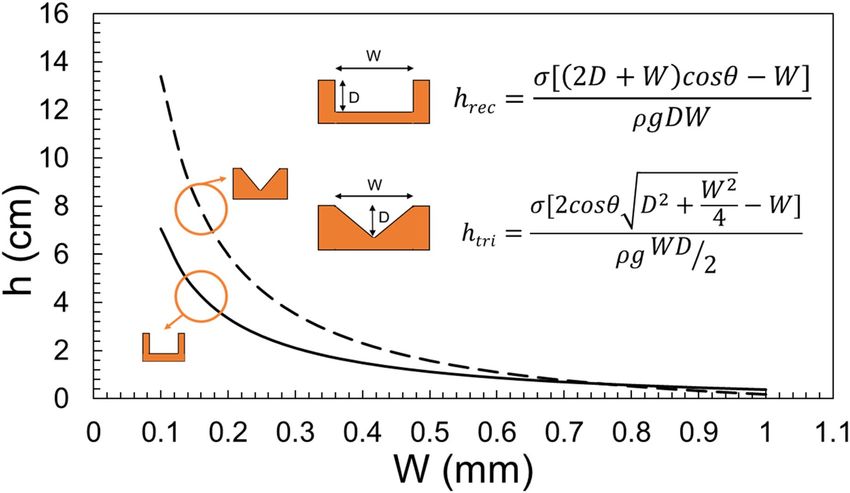
www.nature.com/scientificreports/
Capillary rise equation Groove cross-section Non-dimensional equation References
σ [(2D+W)cosθ −W]
hrec = ρgDWSinα
W 21
Pw = 2D + W h∗rec = cosθ − Pw
Ac = D × W
σ [(πR+2d)cosθ −2R]
hcyl = ρg [2dR+πR2 /2]Sinα
W 23
Pw = π R + 2d h∗cyl = cosθ − Pw
Ac = 2dR + π R2 /2
2
σ 2cosθ D2 + W4 −W
htri = ρgWD/2 Sinα
W 24
W2 h∗tri = cosθ − Pw
Pw = 2 D2 + 4
Ac = W × D/2
σ [(πR+2d+l)cosθ−2R−l]
hcurv = ρg [2dR+dl+Rl+πR2 /2]Sinα
W 23
Pw = π R + 2d + l h∗curv = cosθ − Pw
Ac = 2dR + l(d + R) + π R2 /2
2
σ l+2 D2 + (W−l)
4 cosθ−W
htrap = ρg(l+W)D/2 Sinα
h∗trap = cosθ − W –
(W−l)2 Pw
Pw = l + 2 D2 + 4
Ac = (l + W) × D/2
√
σ 2bE 1−ε 2 cosθ−2bε
hellip = 2
√ ρg [πεb /2]Sinα h∗ellip = cosθ − W 25
Pw = 2bE( 1 − ε2 ) Pw
Ac = π εb2 /2
Table 1. Capillary rise equation for various cross-sections.
dAsl = (2D + W)dy (3)
where, D is the groove depth and W is the grove width. Here, to further generalize the equations, a slanted column
is considered that is tilted with the angle α. Therefore, in general form, the micro-groove is not vertical unless
α = 90, as seen in Fig. 2. Figure 3 shows more details of front and top view of the micro-groove, the surface ten-
sion vectors, and the direction of gravity.
Looking at Fig. 3, the Helmholtz free energy between three interfaces can be written as21,22:
dE = σsv dAsv + σsl dAsl + σlv dAlv (4)
The capillary force is given as “-dE/dy”. It follows that:
Fc = −dE/dy = σlv [(2D + W) cos θ − W] (5)
The capillary force balances the gravity force that is exerted on the weight of the water column, resulting in
the following capillary rise equation for a rectangular cross-section g roove21:
Scientific Reports | (2020) 10:19709 | https://doi.org/10.1038/s41598-020-76682-2 3
Vol.:(0123456789)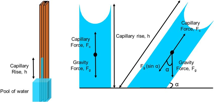
www.nature.com/scientificreports/
Figure 1. A schematic of a drop of a liquid on a flat surface showing three forces of surface tension leading to
Young’s equation under static equilibrium.
Figure 2. Top and front view of a rectangular micro-groove.
σ [(2D + W)cosθ − W]
hrec = (6)
ρgDWSinα
Appendix I provides a detailed and step-by-step approach of how Eq. 6 is concluded. It also explores other
cross-sectional areas and how the capillary rise equation resulted for them.
Following the same approach, the capillary rise equation can be derived for any cross-section. Table 1 lists
the capillary rise equation for six cross-sections of r ectangular21, cylindrical23, curved (modified form o
f23),
trapezoidal, triangular, and general form of hyperellipse. The effect of groove’s width, height, wetting perimeter
(defined later), contact angle, and surface tension can be studied using Eq. (6).
The unified non‑dimensional capillary rise equation
An analytical model that can predict the capillary rise in any cross-section groove is highly desired since it
removes extra steps and unifies all the equations in Appendix I. Equation 6 can be non-dimensionalized by
rearranging and introducing two parameters: Pw is the wetting perimeter and denotes the wetted length of the
cross-section (excluding the liquid–vapor interface; in other words, the wetting perimeter is the solid–liquid
interface length), and Ac is the cross-sectional area. For a rectangular cross-section, Pw and Ac are given as:
Pw = 2D + W (7)
Ac = DW (8)
Scientific Reports | (2020) 10:19709 | https://doi.org/10.1038/s41598-020-76682-2 4
Vol:.(1234567890)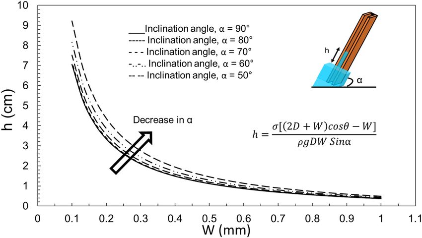
www.nature.com/scientificreports/
Figure 3. Top and front view of a rectangular micro-groove.
For a rectangular cross-section, the non-dimensional capillary rise is:
ρghSinα Ac W
h∗ = ∗ = cosθ − (9)
σ Pw Pw
where L = PWw is a characteristic length scale and is the ratio of the liquid–vapor interface to the wetting perimeter.
Appendix II demonstrates the step-by-step procedure to non-dimensionalize Eq. 6 and conclude Eq. (9). Look-
ing at the capillary rise equations in the Appendix I and using Pw, it is concluded that in fact all the Eqs. A.9, 18,
27, 36, 45, and 54 can be written similarly to Eq. (9). This fact is given in Table 1 where all the non-dimensional
capillary rise equations are listed along with the cross-sectional area and wetting perimeter for each cross-section.
Results and discussion
The effect of the groove’s width, height, wetting perimeter, contact angle, and surface tension can be all studied
using Eq. (6). Although, most of the upcoming plots are for a rectangular groove, a similar approach and conclu-
sions can be made for various cross-sections. Before plotting the non-dimensional parameters, the dimensional
capillary rise is plotted for different cross-sections. Figure 4 shows the effect of depth and width on capillary
height of a rectangular groove. It is concluded that the change in width of the groove has a greater effect on capil-
lary height than the change in depth. Figure 5 presents a comparison between the capillary rise in a rectangular
and triangular groove. It is seen that the capillary rise in a triangular groove is considerably higher than that in
a rectangular cross-section. This fact is explained by the fact that a triangular groove contains half of the liquid
as compared to a rectangular one, therefore, the capillary force is able to take the body of water higher.
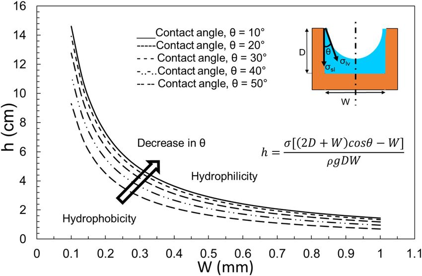
The contact angle has a great effect on the overall capillarity in micro-grooves. Figure 6 plots the effect of
contact angle on capillary height in a rectangular groove. It is concluded that the more hydrophilic the surface,
the higher the capillary rise would be. Although, Fig. 4 was plotted for an inclination angle of 90°, it is possible to
investigate the effect of α. Figure 7 plots the capillary height as the inclination angle drops from 90 to 40 degrees.
It is worth mentioning that for α smaller than 90°, h is the capillary length, the length of rise of the liquid along
the groove, rather than the overall height of the liquid column (refer to Fig. 3 for clarification). It is concluded that
for smaller inclination angles, the liquid travels further to reach the same water height level as a vertical groove
(since the pressure of the pool of water and that of the top of the capillary height should equalize).
The unified non-dimensional capillary rise is given as Eq. (9). Before plotting a general form of this equation,
it is interesting to compare the proposed model with experimental data from the literature. Here, two sets of data
from21 and24 are chosen to see how Eq. 9 can capture the experimental capillary rise in a non-dimensional form.
Figures 8 and 9 compare the predicted h* for a rectangular and triangular cross-section groove, respectively, with
those from the literature. It is seen that the non-dimensional form of h falls within 10% of the experimental data,
therefore, it can be used as a general and unified equation. The reported deviation of experimental data from the
model’s values is typical and expected, given many factors that affect a capillary rise experiment. Possible sources
of this deviation are surface roughness, contact angle variation, and geometry inconsistency21.
Scientific Reports | (2020) 10:19709 | https://doi.org/10.1038/s41598-020-76682-2 5
Vol.:(0123456789)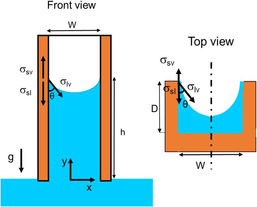
www.nature.com/scientificreports/

                                            Figure 4.  The effect of groove width and height on the capillary rise in a rectangular cross-section for α = 90°.

                                            Figure 5.  A comparison between the capillary rise in a rectangular and triangular cross-section groove,
                                            D = 1 mm, and α = 90°.

          Scientific Reports |   (2020) 10:19709 |               https://doi.org/10.1038/s41598-020-76682-2                                                      6

Vol:.(1234567890)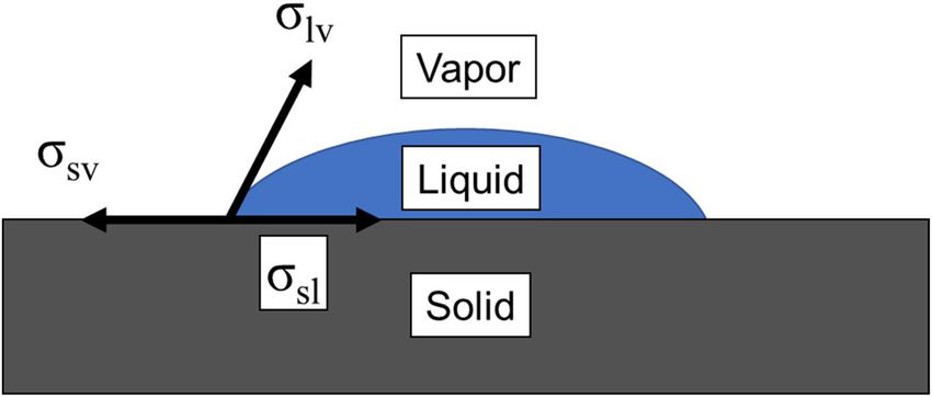
www.nature.com/scientificreports/

                                  Figure 6.  The effect of contact angle on the capillary rise in a rectangular cross-section with D = 1 mm and
                                  α = 90°.

                                  Figure 7.  The effect of inclination angle on the capillary rise in a rectangular cross-section with D = 1 mm.

Scientific Reports |   (2020) 10:19709 |               https://doi.org/10.1038/s41598-020-76682-2                                                   7

                                                                                                                                               Vol.:(0123456789)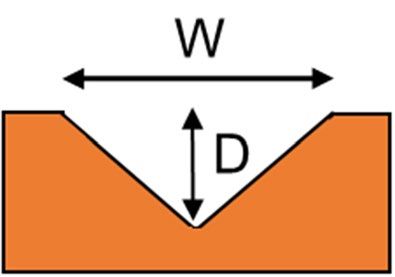
www.nature.com/scientificreports/
Figure 8. A comparison of capillary rise (Eq. 9) with data extracted from21.
Figure 9. A comparison of capillary rise (Eq. 9) with data extracted from24.
Figure 10 plots the final unified non-dimensional form of capillary rise as a function of L, characteristic
length scale. It is seen that for each value of the contact angle, h* is a line that intercepts the x-axis at some point.
Returning to the first assumption in “The capillary rise equation for various cross-sections” section, the maximum
allowable characteristic length scale depends on the contact angle value; i.e. there exists a maximum L, for each
contact angle value, above which the capillary action would not happen for that contact angle. In other words,
for capillary to happen (h* > 0), the characteristic length scale should be smaller than a certain value. This value
Scientific Reports | (2020) 10:19709 | https://doi.org/10.1038/s41598-020-76682-2 8
Vol:.(1234567890)www.nature.com/scientificreports/
Figure 10. The unified non-dimensional form of capillary rise as a function of characteristic length scale and
contact angle. Data from (○21, ∆24, □28, ◊26, × 27).
depends on the contact angle; i.e. with a given contact angle, there exists a maximum characteristic length scale
(hence, a maximum width), above which h* would be zero. As an example, if contact angle is 70°, the maximum
possible characteristic length scale (W/Pw) is ~ 0.34 (Fig. 10). Therefore, by having the P w of the channel, we can
find a maximum width for capillary to happen.
It is also seen that surfaces with a smaller contact angle (more hydrophilic) would have a higher h*. Finally, it is
concluded that the difference between two sets of h* lines increases significantly as the contact angle increases; i.e.
The h* lines for 0° and 10° contact angles are a lot closer to each other than the lines for 50° and 60°, even though
they both have a 10° difference in contact angle. Figure 10 also includes experimental data from Refs.21,24,26,27
and numerical data from28 for reference.
Conclusions
In this study, a unified non-dimensional closed-form analytical solution was proposed that can accurately predict
the capillary rise for any given geometry, and only depends on two parameters: contact angle and a characteris-
tic length scale, defined as the ratio of the liquid–vapor to solid–liquid interface. The effect of a groove’s width,
height, wetting perimeter, contact angle, and surface tension were studied using Eq. (6). It was observed that:
• The change in width of the groove had a greater effect on capillary height than the change in depth,
• The capillary rise in a triangular groove was considerably higher than for other cross-sections,
• The contact angle had a great effect on the overall capillarity in micro-grooves. The more hydrophilic the
surface, the higher the capillary rise, and
• Smaller inclination angles led to a longer liquid travel path.
It was seen that the unified non-dimensional form of h falls within 10% of the experimental data, therefore,
it can be used as a general equation. It was also observed that:
• Using the proposed model, Eq. (9), a maximum characteristic length scale, L, for applicability of capillary
action can be found for a given contact angle,
• Surfaces with smaller contact angle (more hydrophilic) would have a higher h*, and
• The difference between two sets of h* lines increases significantly as the contact angle increases.
Scientific Reports | (2020) 10:19709 | https://doi.org/10.1038/s41598-020-76682-2 9
Vol.:(0123456789)www.nature.com/scientificreports/
This general approach can be used as a unifying tool for designing various engineering solutions that involves
any micro-groove.
Data availability
All data generated or analysed during this study are included in this published article and the supplementary
materials.
Received: 25 August 2020; Accepted: 30 October 2020
References
1. Hopkins, R. C., Faghri, A. & Khrustalev, D. Flat miniature heat pipes with micro capillary grooves. Am. Soc. Mech. Eng. Heat Transf.
Div. HTD 349, 71–80 (1997).
2. Ma, H. B. & Peterson, G. P. Experimental investigation of the maximum heat transport in triangular grooves. J. Heat Transf. 118,
740–746 (1996).
3. Li, X., Wang, J., Hu, Q., Bao, L. & Zhang, H. Experimental and theoretical research on capillary limit of micro heat pipe with com-
pound structure of sintered wick on trapezium-grooved substrate. Heat Mass Transf. und Stoffuebertragung 49, 381–389 (2013).
4. Weibel, J. A. & Garimella, S. V. Recent advances in vapor chamber transport characterization for high-heat-flux applications.
CTRCRes. Public. https://doi.org/10.1016/B978-0-12-407819-2.00004-9 (2013).
5. Zhang, T. T., Yang, W. J., Lin, Y. F., Cao, Y., Wang, M., Wang, Q., & Wei, Y. X. Numerical study on flow rate limitation of open
capillary channel flow through a wedge. Advanc. Mech. Eng. 8(4) 1–11, https://doi.org/10.1177/1687814016645487 (2016).
6. Haake, D., Klatte, J., Grah, A. & Dreyer, M. E. Flow rate limitation of steady convective dominated open capillary channel flows
through a groove. Microgravity Sci. Technol. 22, 129–138 (2010).
7. Chen, T. Capillary force-driven fluid flow in open grooves with different sizes. J. Thermophys. Heat Transf. 29, 594–601 (2015).
8. Ayyaswamy, P. S., Catton, I. & Edwards, D. K. Capillary flow in triangular grooves. J. Appl. Mech. Trans. ASME 41, 332–336 (1974).
9. Raphaël, E. Capillary rise of a wetting fluid in a semi-circular groove. J. Phys. 50, 485–491 (1989).
10. Rye, R. R., Mann, J. A. & Yost, F. G. The flow of liquids in surface grooves. Langmuir 12, 555–565 (1996).
11. Romero, L. A. & Yost, F. G. Flow in an open channel capillary. J. Fluid Mech. 322, 109–129 (1996).
12. Hartge, K. H., Bachmann, J. & Woche, S. K. Influence of the cross-section shape in the capillaries on the wetting properties dem-
onstrated by the calculated wetting angles. Int. Agrophys. 18, 11–16 (2004).
13. Long, L. & Zhang, B. The distribution of fluids in irregular capillary tubes: a new capillary model based on the single-corner capil-
lary. J. Pet. Explor. Prod. Technol. 8, 341–350 (2018).
14. Kim, J., Moon, M. W. & Kim, H. Y. Capillary rise in superhydrophilic rough channels. Phys. Fluids 32, 032105 (2020).
15. Abadi, G. B. & Bahrami, M. Combined evaporator and condenser for sorption cooling systems: a steady-state performance analysis.
Energy 209, 118504 (2020).
16. Xia, Z. Z., Yang, G. Z. & Wang, R. Z. Capillary-assisted flow and evaporation inside circumferential rectangular micro groove. Int.
J. Heat Mass Transf. 52, 952–961 (2009).
17. Honschoten, J. W. V., Brunets, N. & Tas, N. R. Capillarity at the nanoscale. Chem. Soc. Rev. 39, 1096–1114 (2010).
18. Young, T. An essay on the cohesion of fluids. Philos. Trans. R. Soc. 17, 65–87 (1805).
19. Whyman, G., Bormashenko, E. & Stein, T. The rigorous derivation of Young, Cassie–Baxter and Wenzel equations and the analysis
of the contact angle hysteresis phenomenon. Chem. Phys. Lett. 450, 355–359 (2008).
20. Roura, P. & Fort, J. Local thermodynamic derivation of Young’s equation. J. Colloid Interface Sci. 272, 420–429 (2004).
21. Wang, H. J., Tsai, H. C., Chen, H. K. & Shing, T. K. Capillarity of rectangular micro grooves and their application to heat pipes.
Tamkang J. Sci. Eng. 8, 249–255 (2005).
22. Carey, V. P. Liquid-vapor phase-change phenomena : an introduction to the thermophysics of vaporization and condensation processes
in heat transfer equipment - Ghent University Library (Hemisphere, Washington, 1992).
23. Yang, D., Krasowska, M., Priest, C., Popescu, M. N. & Ralston, J. Dynamics of capillary-driven flow in open microchannels. J. Phys.
Chem. C 115, 18761–18769 (2011).
24. Deng, D., Tang, Y., Zeng, J., Yang, S. & Shao, H. Characterization of capillary rise dynamics in parallel micro V-grooves. Int. J. Heat
Mass Transf. 77, 311–320 (2014).
25. Bahrami, M., Yovanovich, M. M. & Culham, J. R. Pressure drop of fully-developed, laminar flow in microchannel of arbitrary
cross-section. J. Fluids Eng. Trans. ASME 128, 1036–1044 (2006).
26. Fu, R. et al. Investigation of the influence of F
e3O4–water nanofluids on capillary performance in microgrooves wick. Appl. Therm.
Eng. 182, 115899 (2021).
27. Deng, D., Tang, Y., Huang, G., Lu, L. & Yuan, D. Characterization of capillary performance of composite wicks for two-phase heat
transfer devices. Int. J. Heat Mass Transf. 56, 283–293 (2013).
28. Ouali, F. F. et al. Wetting considerations in capillary rise and imbibition in closed square tubes and open rectangular cross-section
channels. Microfluid. Nanofluidics 15, 309–326 (2013).
Acknowledgment
The authors are thankful for the financial support provided by the Natural Sciences and Engineering Research
Council of Canada under the NSERC I2IPJ/530368-2018: Idea to Innovation and NSERC ACCPJ/536076-18:
Advancing Climate Change Science in Canada grant.
Author contributions
G.B.A. and M.B. designed the study and G.B.A. wrote the manuscript. All authors reviewed the manuscript.
Competing interests
The authors declare no competing interests.
Additional information
Supplementary information is available for this paper at https://doi.org/10.1038/s41598-020-76682-2.
Correspondence and requests for materials should be addressed to G.B.A.
Reprints and permissions information is available at www.nature.com/reprints.
Scientific Reports | (2020) 10:19709 | https://doi.org/10.1038/s41598-020-76682-2 10
Vol:.(1234567890)www.nature.com/scientificreports/
Publisher’s note Springer Nature remains neutral with regard to jurisdictional claims in published maps and
institutional affiliations.
Open Access This article is licensed under a Creative Commons Attribution 4.0 International
License, which permits use, sharing, adaptation, distribution and reproduction in any medium or
format, as long as you give appropriate credit to the original author(s) and the source, provide a link to the
Creative Commons licence, and indicate if changes were made. The images or other third party material in this
article are included in the article’s Creative Commons licence, unless indicated otherwise in a credit line to the
material. If material is not included in the article’s Creative Commons licence and your intended use is not
permitted by statutory regulation or exceeds the permitted use, you will need to obtain permission directly from
the copyright holder. To view a copy of this licence, visit http://creativecommons.org/licenses/by/4.0/.
© The Author(s) 2020
Scientific Reports | (2020) 10:19709 | https://doi.org/10.1038/s41598-020-76682-2 11
Vol.:(0123456789)You can also read