GF100 Series DATA SHEET - Mass Flow Controllers & Meters - Brooks Instrument
←
→
Page content transcription
If your browser does not render page correctly, please read the page content below
DATA SHEET
                                                           Mass Flow Controllers & Meters

                                                GF100 Series
                                       Metal Sealed, Digital,
               				   High Purity/Ultra-High Purity Thermal
GF100 Series        Mass Flow Controllers & Meters for Gases

                   Designed for semiconductor, MOCVD, and other gas flow control applications that require
                   a high purity all-metal flow path, the Brooks® GF100 Series mass flow controllers and
                   meters deliver outstanding performance, reliability, and flexibility. Highlights of the GF
                   Series industry-leading features include: ultra fast 300 millisecond settling time, Multi-
                   Flo™ gas and range programmability, optional pressure transient insensitivity (PTI), local
                   display, extremely low wetted surface area, and corrosion resistant Hastelloy® sensor tube
                   and valve seat. The GF100 Series has been marathon tested to over three times the semi-
                   conductor industry standard for reliability, ensuring repeatable low-drift performance
                   over time. An independent diagnostic/service port permits users to troubleshoot or change
                   flow conditions without removing the mass flow controller from service.
                   The flagship GF125 is a second generation multi-variable, pressure transient insensitive
                   mass flow controller. This product builds upon Brooks’ leadership position in pressure
                   transient insensitive (PTI) mass flow controller technology, minimizing process gas flow
                   variation due to pressure and temperature fluctuations. The GF125 enables customers to
                   simplify and reduce the size and cost of gas panels by eliminating the need for point of
                   use pressure regulators, pressure transducers, and associated hardware.
                   MultiFlo™ gas and range programmability, a patented technology developed and refined
                   by Brooks over the last 10 years, has changed the mass flow controller industry by offer-
                   ing customers the ability to select new gas calibrations and full scale ranges without the
                   trouble and cost of removing the mass flow controller from the gas line. The GF Series
                   fourth generation MultiFlo technology continues to lead the market with the most accu-
                   rate and broadest range performance through extensive refinement and physical valida-
                   tion on critical process gases.
                   The GF100 Series is a highly configurable platform based on a novel modular
                   architecture. Already widely adopted by semiconductor, vacuum thin film, solar, and
                   related customers, the GF100 Series feature set was carefully selected to enable drop-in
                   replacement and upgrade of most brands of metal-seal mass flow controllers, including
                   the former Celerity, UNIT, Tylan, and Mykrolis brands. With the wide range of options
                   and features available, the GF100 Series provides users with a path to simplification and
                   standardization, greatly reducing spares inventory and support costs.

                                  BrooksInstrument.com                                                          1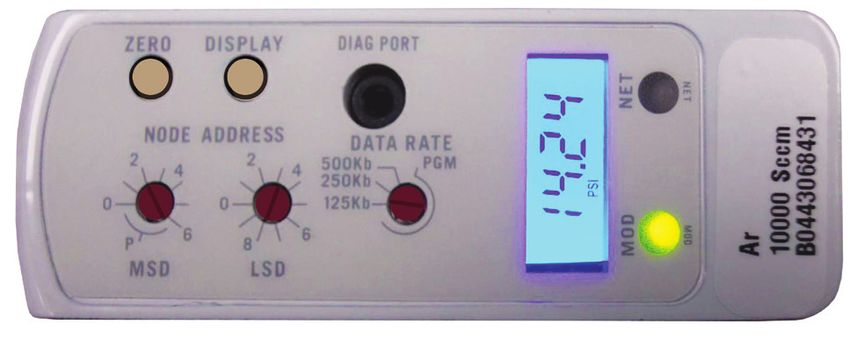
Features and Benefits

         Convenient Service Port                                                                          User Interface
         • Easy diagnostics and troubleshooting                                                           • Easy installation, start-up, and operation
         • Independent of tool communication

                                                                                                             Magnetically Coupled Valve
                                                                                                             • Corrosion resistant all metal valve
                                                                                                             • Diaphragm free design, unaffected by
                                                                                                               differential pressure
                                                                                                             • High purge rate capability
                                                                                                             • Tested for over seven million cycles
                                                                                                               with no failures

    Pressure Sensor
    • Stable flow control                                                                                     Second Generation T-Rise Sensor
      regardless of upsets or                                                                                 • Excellent long-term stability
      fluctuations in delivery                                                                                  (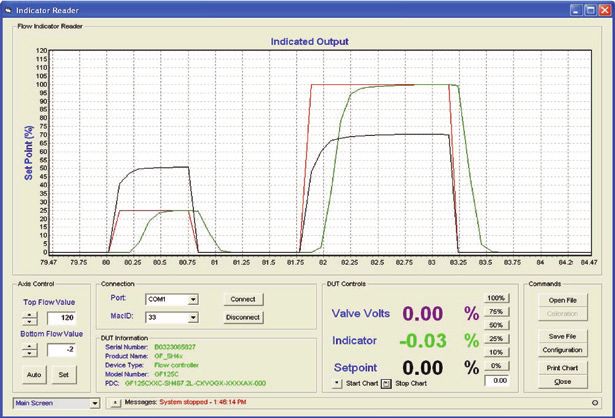
Product Description
120
100
By combining Brooks’ patented flow sensor technology with
a high speed ARM processor and fast acting diaphragm free
valve assembly, the GF100 Series delivers up to 3 times 80
Set Point (% of Full Scale)
faster response and settling time compared to other mass flow
controllers, enabling: 60
• Improved wafer throughput by reducing
nonproductive flow settling steps 40
• Critical Etch processes requiring ultrafast 1-2 second etch
steps 20
• Reduced diverted gas consumption and associated
abatement costs 0
0 1 2 3 4 5
• Time-sensitive gas delivery steps in Atomic Layer Deposition Time in Seconds
• For processes requiring a slow ramped gas turn-on or -20
time critical transitions between flow rates. A user Set-Point (% FS) Brooks GF125 Competitor A Competitor B
Comparison of GF vs Competitors response time
programmable ramp function is provided to ascending & decending setpoints
MultiFlo™ Gas and Range Configurability
A major advancement over traditional single point gas
conversion factors, Brooks MultiFlo technology delivers up to
a three-times improvement in process gas accuracy. This is
MFC
MFC
MFC
MFC
achieved through advanced gas modeling optimized through
actual gas testing providing compensation for non-linear GF Series 3.6L He 3.6L Ar 1.6L Xe 2.6L H2
gases. MultiFlo also allows the device to be quickly and easily MFC
MFC
MFC
MFC
MFC
configured for another gas and/or flow range without sacrificing
accuracy or rangability. Selecting a new gas automatically
creates a new calibration curve, establishes optimized PID = 2.6L CO 2.1L HBr 2.6L N2 1.6L C12
MFC
MFC
MFC
MFC
settings for dynamic control, automatically compensates for gas
density effects, and ensures smooth, overshoot-free transitions
between flow rates with excellent steady-state stability. 1.8L H2Se 2.0L NH3 1.9L PH3 1.7L COS
MFC
MFC
MFC
Brooks MultiFlo technology offers unparalleled flexibility; a
single device can be programmed for thousands of different
1.5L SiH4 1.3L NF3 1.5L COF2
...
gas and flow range configurations.
TM
MultiFlo technology allows one GF Series to be programmed
Re-programming is simple and fast; a new gas and range can for thousands of different gases and flow ranges
be programmed in under 30 seconds. Brooks provides a full gas
database to ensure the true value of MultiFlo is realized:
• Dramatically reduces inventory costs
• Mass flow controller full scale flow range can re-scaled down Competito r A Competito r B
typically by a factor of 3:1 with no impact on accuracy, # of GF1xx Series 2 Model s 4 Model s
turndown or leak by specifications, for optimum process and Platforms Range Range Range
1 3 - 10 10 1-5
inventory flexibility 2 11 - 30 17.5 6 - 14
• Up to 40% fewer configurations required to support typical 3 31 - 92 30 15 - 27
4 93 - 280 55 28 - 38
etch and CVD processes verses our closest competitor 5 281 - 860 100 39 - 71
• Widest process gas coverage through extensive gas library 6 861 - 2,600 175 72 - 103
7 2,601 - 7,200 300 104 - 192
• Mass flow controllers can be replaced in only a few minutes 8 7,201 - 15,000 550 193 - 279
• Off-the shelf spares programmability enables rapid process 9
10
15,001 - 30,000
30,001 - 40,000
1,000
1,750
280 - 754
755 - 2,037
recovery 11 40,001 - 55,000 3,000 2,038 - 5,500
• Maximum flexibility for research applications 12
13
5,500
10,000
5,501 - 11,000
11,001 - 30,000
14 22,000 30,001 - 50,000
15 30,000
16 50,000
The Brooks Advantage! Less platforms means more process
flexibility and lower cost of spares.
3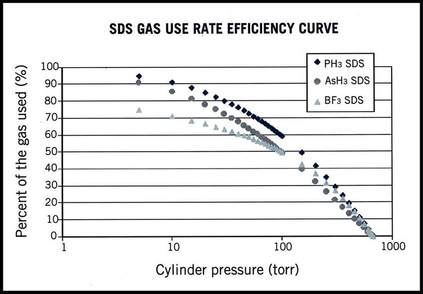
Product Description

MultiFloTM Configurator Accessory Kits:
  778Z010ZZZ          Basic MultiFlo Configurator Kit
                      *Software, MultiFlo Configurator
  124Y211AAA          Best/Multiflo Cable - USB to RS485
  778Z011ZZZ          Basic MultiFlo Configurator Kit
		                    w/Power Supply and Adapter Cables
		                    *Software, MultiFlo Configurator
  124Y211AAA          Best/Multiflo Cable - USB to RS485
  A332295001          Power Supply MFC
  A332297002          Cable, Power, 9-Pin
  A332297001          Cable, Power, DeviceNet
* MultiFlo Configurator Software is available on the Brooks
  Instrument website at: www.BrooksInstrument.com/MultiFlo

Pressure Transient Insensitivity (PTI) (GF125 only)                Pressure Flucuations in Non-Pressure Transient Insensitivty MFC
Cost and space constraints are driving gas panel designers
to remove point of use pressure regulators and pressure
monitoring components, placing more burden on the mass
flow controller to control accurately under dynamic pressure
conditions. Conventional mass flow controllers react strongly
to small inlet pressure fluctuations resulting in unstable
performance and unpredictable accuracy (see Non-Pressure
Insensitive MFC). This drove Brooks to develop Pressure
Transient Insensitive mass flow controller technology (PTI-MFC).
The GF125 PTI-MFC is a second generation PTI-MFC utilizing
a patented control algorithm that inverts the pressure signal,
compares it to the pre-fluctuation signal and drives real-time
valve position compensation to maintain stable flow. Enhanced
pressure transient insensitivity is achieved through faster
sensing, faster processing, and a reduction in internal dead-
volume between the sensors and valve orifice.
Advanced Thermal Flow Measurement Sensor
Brooks’ proprietary sensor technology combines:
                                                                    Stable Pressure with Pressure Transient Insensitivty GF Device
• Improved signal to noise performance for improved accuracy
  at low setpoints
• Improved reproducibility at elevated temperatures through
  new isothermal packaging, onboard conditioning
  electronics with ambient temperature sensing and
  compensation
• Improved long-term stability through enhanced sensor
  manufacturing and burn in process
• Highly corrosion resistant Hastelloy C-22 sensor tube
• Optimized temperature profile for gases prone to thermal
  decomposition
• Unique orthogonal sensor mounting orientation
   -Eliminates sensor drift caused by valve heating effects
   -Eliminates thermal siphoning effects for the most common
    mounting orientations

4
Product Description
High Purity Flow Path
All metal, corrosion resistant flow path with reduced surface area
and un-swept volumes for faster dry-down during purge steps:
• SEMI F-20 compliant wetted flow path
• 4 µ inch Ra max surface finish standard (10 µ inch Ra on
GF100)
• Highly corrosion resistant Hastelloy C-22 valve seat and
jet orifice
Extensive Mechanical Configuration Support
GF100 Series supports all metal seal / UHP industry gas
connection interface standards for full OEM and process coverage
• Downport 80mm and 92mm C-seal and W-Seal, on 1.125” and
1.5” bodies
• Downport 80mm CS seal on 1.5” body High Purity Flow Path
• 124 mm 1/4” VCR Male on 1.5” body
Enhanced Diagnostics
The mass flow controller remains the most complex and critical
component in gas delivery systems. When dealing with UHP gas
distribution or highly toxic or corrosive gases, removing the mass
flow controller to determine if it is faulty should be the last resort.
In response to this, Brooks pioneered smarter mass flow
controllers with embedded self test routines and introduced an
independent diagnostic/service port to provide the user with a
simple interface, for troubleshooting without disturbing flow
controller operation.
MFC on Gas Box
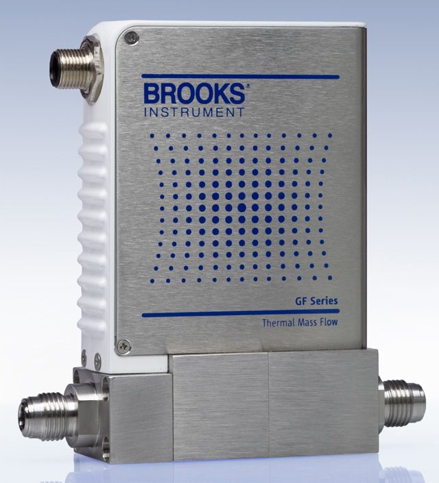
User Interface
The user interface has a high visibility LCD display that provides
a local indication of Flow (%), Temperature (°C), Pressure (PSIA/
KPa) and Network Address, selectable through the Display button.
A Zero button provides a simple means to re-zero the mass flow
controller as part of scheduled maintenance.
Communication Interface
The GF100 Series supports analog 0-5 Vdc, RS485, and
DeviceNet™ communication protocols. A range of low profile
adapter cables facilitate replacing older mass flow controllers
with the GF100 Series eliminating the need to carry mass flow
Communication Interface
controllers of same gas/range but different electrical connectors.
5
Product Specifications (Standard GF Series)
    Performance¹                                                                 GF100                                                      GF120                                          GF125
    Full Scale Flow Range                                                                                                            3 sccm to 55 slm
    Flow Accuracy                                                                                                +1% S.P. > 35-100%,                  +0.35% F.S. 2-35%
    Repeatability & Reproducibility                                                                     5-100% = ± 0.15% of S.P.                      2-5% = ± 0.015% of F.S.
    Linearity                                                                                                          ± 0.5% F.S. (included in accuracy)
    Response Time (Setting Time)                                                                                                                                                 300ms (3-860 sccm N2 Eq.)
    Normally Closed Valve                                                        < 1 sec                                                     700ms                             400ms (861-7200 sccm N2 Eq.)
                                                                                                                                                                              500ms (7201-30000 sccm N2 Eq.)
Product Description GF120 Safe Delivery System (SDS) Options
The GF120 Safe Delivery System (SDS®) is Brooks’ state-of-the-art low
pressure drop mass flow controller for the delivery of sub atmospheric
safe delivery system (SDS) gases used in Implant and Etch processes. The
Brooks GF120 (SDS) models are available in full scale flow ranges 4-25
sccm (option GF120XSL) or >25 sccm to 1 slpm (option GF120XSD).
These expensive, hazardous gases are adsorbed onto a solid medium
within the gas cylinder, remaining below atmospheric pressure despite
containing up to 15 times more dopant than conventional pressurized
sources.
The amount of gas that can be extracted from the SDS controlled
cylinder is highly dependent upon the final cylinder pressure. This is
illustrated in SDS desorption species information in the SDS Gas Use Rate
Efficiency Curve. Most of the gas is released at pressures below 100 Torr.
The minimum cylinder pressure that can be reached is limited by the
conductance of the mass flow controller regulating the flow. Most mass
flow controllers require a 50 Torr differential pressure at flow rates of 5
sccm. At this 50 Torr limit, only ~65% of the dopant can be extracted
from the adsorbent medium at normal operating temperatures. The
GF120 (SDS) low pressure operation enables a further 30% of the
dopant to be extracted, driving significant cost savings in SDS gases
and equipment OEE.
Product Specifications (GF120XSD and GF120XSL) Options
Performance GF120XSL GF120XSD
Full Scale Flow Range (N2 Eq.) 4 - 25 sccm >25sccm to 1 slpm
Gases Supported¹ AsH3, PH3, BF3, SiF4 , GeF₄, AsF₅, PF₃,
H₂Se, HMDSO, HMDSN, H₂O, Ar , Xe, N₂O, N₂
MultiFlo Programmable Not Configurable
Flow Accuracy ±1% S.P. >35% F.S. ±0.35% F.S. 50 sccm to 1 slpm > 50 Torr
Maximum Pressure 500 psia max
Pressure Insensitivity Not Available
DifferentialPressure4 10 Torr-30 psid typical (1.33-207 kPa typical)
Valve Configuration Normally Closed
Ambient Temperature Range 10OC-50OC
Zero Temperature Coefficient 0.05% F.S. per OC, Zero: 0.005% F.S. per OC
¹ Consult factory for other gases.
² GF120 Pressure ratings apply to SDS configurations.
³ Performance at minimum inlet pressure will be gas and flow range dependent. Consult Technical Support for details.
⁴ Typical pressure drop. Actual pressure drop will be gas and flow dependent. Consult Technical Support for details.
7Electrical Interface Options
Base I/O Options I/O Options Using Base Model and Adapter Cable
PDC Ordering Code G1
Description: Industry standard
Analog / RS485 interface
123
A range of low profile adapter cables have been developed to support
replacing older generation MFC’s with different pinout configurations. The
PDC Ordering Code GX base MFC will be either a G1, TX or SX configuration, depending on the
Description: OEM specific product being replaced.
Analog / RS485 interface.
Display and top plate PDC Ordering Code PDC Ordering Code: T1
re-oriented 180o UX Description: SX base Description: TX base I/O with
I/O with 7003550 adapter for 7003551 adapter for compatibility
123 compatibility with Unit UDU15 with IFlow DB15 & TN 15 pin
PDC Ordering Code DX
Description: Industry standard
ODVA compliant DeviceNet
interface
PDC Ordering Code: FX / JX PDC Ordering Code: EX
PDC Ordering Code TX Description: SX base I/O with Description: GX base I/O with
Description: Industry standard 7003069 (FX)/7001814 (JX) 7003083 adapter for compatibility
Analog only interface adapter for compatibility with with Unit “E”, IN “L”, “R”
Unit UDF9/UDJ9
PDC Ordering Code SX
Description: Industry standard
Analog 9-Pin Sub D connector
and dual RJ11 RS485 ports
PDC Ordering Code: KX PDC Ordering Code: BX
PDC Ordering Code BB Description: G1 base I/O with Description: G1 base I/O with
Description: Industry standard 7003298 adapter for compatibility 7003590 adapter for
ODVA compliant DeviceNet with Unit UDK15 compatibility with Brooks 15-Pin D
interface, Plus a separate
Analog 0-5 Vdc Connector
All Base I/O options include:
Diagnostic port communication RS485 via 2.5mm jack
Other adapter options are available for the GF Series. Please contact Brooks Customer
Service for more information.
8Product Dimensions
Downport
Downport Configurations
Configurations
Electrical Connector Electrical Connector Electrical Connector
G1/GX/TX Specific Dimensions DX/BB Specific Dimensions SX Specific Dimensions
E
3.67in 3.29in
93mm 84mm
.98in
25mm
5.09in
129mm 4.45in
G 113mm
3.75in
95mm
F
A Fitting Option Code Seal Type Dim A Dim B Dim C Dim D Dim E Dim F Dim G
CX C-SEAL 92mm [3.62in] 105mm [4.13in] 22mm [0.86in] 28mm [1.12in] 83mm [3.28in] 25mm [1.00in] 127mm [5.00in]
EX W-SEAL 79.8mm[3.14in] 93mm [3.66in] 30mm [1.18in] 39mm [1.53in] 72mm [2.82in] 25mm [1.00in] 127mm [5.00in]
C D WX W-SEAL 92mm [3.62in] 105mm [4.13in] 22mm [0.86in] 28mm [1.12in] 83mm [3.28in] 25mm [1.00in] 127mm [5.00in]
DX C-SEAL 79.8mm[3.14in] 93mm [3.66in] 22mm [0.86in] 28mm [1.12in] 72mm [2.82in] 25mm [1.00in] 127mm [5.00in]
YX W-SEAL 79.8mm[3.14in] 93mm [3.66in] 22mm [0.86in] 28mm [1.12in] 72mm [2.82in] 25mm [1.00in] 127mm [5.00in]
AX C-SEAL 92mm [3.62in] 105mm [4.13in] 30mm [1.18in] 39mm [1.53in] 83mm [3.28in] 25mm [1.00in] 127mm [5.00in]
B BX W-SEAL 92mm [3.62in] 105mm [4.13in] 30mm [1.18in] 39mm [1.53in] 83mm [3.28in] 25mm [1.00in] 127mm [5.00in]
LX C-SEAL 92mm [3.62in] 105mm [4.13in] 22mm [0.86in] 28mm [1.12in] 83mm [3.28in] 25mm [1.00in] 127mm [5.00in]
VCR Configurations
9Model Code
Code Description Code Option Option Description1
I. Base Model Code GF High Purity/Ultra High Purity Digital Mass Flow Controllers
II. Package / Finish Specifications 100 Flow range 3 sccm -55 slpm N2 Eq.; + 1.0% SP Accuracy; 1 sec Response; 10 Ra
120 Flow range 3 sccm -55 slpm N2 Eq.; + 1.0% SP Accuracy; 700 msec Response; 5 Ra
125 Pressure Transient Insensitive (PTI) Flow range 3 sccm -55 slpm N2 Eq.; + 1.0% SP Accuracy;
300-700 msec Response; 5 Ra
III. Configurability C MultiFlo capable. Standard bins or specific gas/range may be selected.
X Not MultiFlo capable. Specific gas/range required. (must select w/ SD, SL or HA special application)
IV. Special Application XX Standard
SL Safe Delivery System (GF120 Only) Full scale flow range; 4 to 25 sccm, Nitrogen Equivalent
SD Safe Delivery System (GF120 Only) Full scale flow range; >25 sccm to 1 slpm, Nitrogen Equivalent
V. Valve Configuration O Normally Open valve (not available with SD, SL or HA options)
C Normally Closed valve (must select with SD, SL or HA special application)
M Meter (No Valve)
VI.
Gas or SH MultiFlo Bin XXXX XXXX Specific Gas Code & Range, i.e. “0004” = Argon and “010L” = 10 slpm (must select w/ SD, SL or
HA special application).
SH40 010C Standard Configuration #40, 3-10 sccm Nitrogen Equivalent (0° C Reference)
SH41 030C Standard Configuration #41, 11-30 sccm Nitrogen Equivalent (0° C Reference)
SH42 092C Standard Configuration #42, 31-92 sccm Nitrogen Equivalent (0° C Reference)
SH43 280C Standard Configuration #43,93-280 sccm Nitrogen Equivalent (0° C Reference)
SH44 860C Standard Configuration #44, 281-860 sccm Nitrogen Equivalent (0° C Reference)
SH45 2.6L Standard Configuration #45, 861-2600 sccm Nitrogen Equivalent (0° C Reference)
SH46 7.2L Standard Configuration #46, 2601-7200 sccm Nitrogen Equivalent (0° C Reference)
SH47 015L Standard Configuration #47, 7201-15000 sccm Nitrogen Equivalent (0° C Reference)
SH48 030L Standard Configuration #48, 15001-30000 sccm Nitrogen Equivalent (0° C Reference)
SH49 040L Standard Configuration #49, 30001-40000 sccm Nitrogen Equivalent (0° C Reference)
SH50 055L Standard Configuration #50, 40001-55000 sccm Nitrogen Equivalent (0° C Reference)
VII. Fitting VX 1-1/2” body width, 124mm 1/4” VCR male
VS 1-1/8” body width, 124mm 1/4” VCR male
CX 1-1/8” body width, 92mm C Seal
DX 1-1/8” body width, 79.8mm C Seal
EX 1-1/2” body width, 79.8mm W Seal
WX 1-1/8” body width, 92mm W Seal
YX 1-1/8” body width, 79.8mm W Seal
AX 1-1/2” body width, 92mm C Seal
BX 1-1/2” body width, 92mm W Seal
LX 1-1/8” body width, 92mm C Seal w/Poke Yoke
AS 1-1/2” body width, 92mm 0.440” large bore C Seal (only for bins SH45-SH50)
VIII. Downstream Condition A Atmosphere
V Vacuum; Default for SD, SL and HA special application
IX. Sensor O Default Sensor Orientation
10Model Code
Code Description Code Option Option Description1
X. Connector BX Cable adapter to 15 pin D Brooks (Unit “B”,”N”) adapts G1 base
EX Cable adapter to Card Edge (w/out VTP), RS485 through RJ11 jacks (Unit”E”; IN “L”, “R”) adapts GX base
(Not Available on 79.8mm fitting DX, YX, EX)
FX Cable adapter with 9 pin STEC pin-out & jack screws (w/VTP) (Unit”F”,”O”) adapts SX base
GX 9-Pin D with RS485 (Unit”G”); display and overlay 180o orientation
G1 9-Pin D with RS485 (Unit”G”) (Not Available on 79.8mm fitting DX, YX, EX)
JX Cable adapter with 9 pin STEC pin-out & jack screws (w/VTP) (Unit”J”,”W”) adapts SX base
KX Cable adapter to MKS 15-Pin D (Unit “K”) adapts G1 base
SX 9 pin D with STEC pin-out (w/VTP) (Unit”S”,”Q”)
TX 9 pin D with UDT9 pin-out (UDT9) (Not Available on 79.8mm fitting DX, YX, EX)
T1 Cable adapter to 15 pin D (IFlow DB15 & TN 15 pin) adapts TX base (Not Available on 79.8mm fitting DX, YX, EX)
UX Cable adapter to 15 pin D (w/VTP) (Unit & TN “U”) adapts SX base
BB DeviceNetTM Analog (Not Available on 79.8mm fitting DX, YX, EX)
DeviceNet Standard Configuration Parameters
Poll IO Poll IO Poll IO External
Power On Full Scale Full Scale Full Scale Instance Instance State Baud
I/O Connector State Setting Setting Setting Producer Consumer Transition Rate
D0 DeviceNet 5 Pin Micro Idle Count Integer 6000h 2 7 Executing 500KB
D1 DeviceNet 5 Pin Micro Idle Count Integer 6000h 21 7 Executing 500KB
D2 DeviceNet 5 Pin Micro Idle SCCM Float 7FFFh 13 19 Executing 500KB
D3 DeviceNet 5 Pin Micro Idle Count Integer 6000h 22 7 Executing 500KB
D4 DeviceNet 5 Pin Micro Executing Count Integer 6000h 22 8 Executing 500KB
D5 DeviceNet 5 Pin Micro Idle Count Integer 6000h 6 8 Executing 500KB
D6 DeviceNet 5 Pin Micro Idle Count Integer 7FFFh 3 7 Executing 500KB
D7 DeviceNet 5 Pin Micro Idle Count Integer 7FFFh 6 8 Executing 500KB
D8 DeviceNet 5 Pin Micro Idle Count Integer 6000h 3 7 Executing 500KB
D9 DeviceNet 5 Pin Micro Executing Count Integer 6000h 2 7 Executing 500KB
DA DeviceNet 5 Pin Micro Idle Count Integer 7FFFh 22 7 Executing 500KB
DB DeviceNet 5 Pin Micro Idle Count Integer 6000h 22 8 Executing 500KB
DC DeviceNet 5 Pin Micro Idle Count Integer 7FFFh 3 7 Idle 500KB
DD DeviceNet 5 Pin Micro Executing Count Integer 7FFFh 22 8 Executing 500KB
DE DeviceNet 5 Pin Micro Executing Sccm Float 6000h 15 19 Executing 500KB
DX DeviceNet 5 Pin Micro To be defined by CSR
Code Description Code Option Option Description1
XI. Customer Special Request XXXX Customer Special Request Number; required with “DX, BB” Conn. Option to define DNet settings
XII. Auto Shut-Off A Auto Shut-Off (Included) Default for SD and SL special application
X Auto Shut-Off (Not Included) (Must be selected for meter)
XIII. Auto Zero X Auto Zero (Not Included)
XIV. Reference Temperature 000 0oC Reference Calibration (Standard) - Default Setting
Sample Standard Model Code
I II III IV V VI VII VIII IX X XI XII XIII XIV
GF 100 C XX M - SH40010C - VX A O GX - XXXX A X - 000
Sample Safe Delivery System (SDS) Model Code
I II III IV V VI VII VIII IX X XI XII XIII XIV
GF 120 X SD C - XXXXXXXX - EX V O SX - XXXX A X - 000
11Service and Support
Brooks is committed to assuring all of our customers receive the ideal flow solution for their application, along with outstanding
service and support to back it up. We operate first class repair facilities located around the world to provide rapid response and
support. Each location utilizes primary standard calibration equipment to ensure accuracy and reliability for repairs and recalibration
and is certified by our local Weights and Measures Authorities and traceable to the relevant International Standards.
Visit www.BrooksInstrument.com to locate the service location nearest to you.
START-UP SERVICE AND IN-SITU CALIBRATION
Brooks Instrument can provide start-up service prior to operation when required. For some process applications, where ISO-9001
Quality Certification is important, it is mandatory to verify and/or (re)calibrate the products periodically. In many cases this service
can be provided under in-situ conditions, and the results will be traceable to the relevant international quality standards.
CUSTOMER SEMINARS AND TRAINING
Brooks Instrument can provide customer seminars and dedicated training to engineers, end users, and maintenance persons. Please
contact your nearest sales representative for more details. Due to Brooks Instrument’s commitment to continuous improvement of
our products, all specifications are subject to change without notice.
TRADEMARKS
Brooks.............................................................. Brooks Instrument, LLC
All other trademarks are the property of their respective owners.
DS-TMF-GF100-Series-MFC-eng-2021-07
2021
12You can also read