SHIP EXPERIMENT COMPREHENSIVE DESIGN STUDY REPORT - CERN DOCUMENT SERVER
←
→
Page content transcription
If your browser does not render page correctly, please read the page content below
SHiP Experiment
                                                        C OMPREHENSIVE D ESIGN S TUDY REPORT

                                                                          SHiP Collaboration

                                                                                   Abstract

                                                Following the completion of the Comprehensive Design Study of the SHiP detector, this
                                                document summarises the status of the physics and the detector and outlines a three-year
CERN-SPSC-2019-049 / SPSC-SR-263

                                                design and development plan towards Technical Design Reports. The document concludes
                                                with an overall road map and updated costs for the detector R&D and construction. With
                                                the submission and review of this document, together with the SHiP Progress Report [1]
                                                and the Beam Dump Facility Yellow Report [2], the SHiP Collaboration is ready to proceed
                                                with the preparation of Technical Design Reports, pending approval.
                                   12/12/2019

                                                Keywords
                                                SHiP, Comprehensive Design Study, SPS, CERN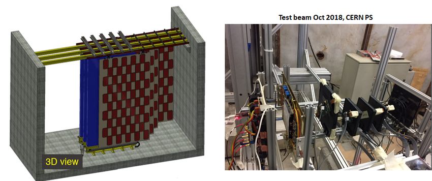
The SHiP Collaboration

C. Ahdida44 , A. Akmete48 , R. Albanese14,d,h , A. Alexandrov14 , A. Anokhina39 , S. Aoki18 ,
G. Arduini44 , E. Atkin38 , N. Azorskiy29 , J.J. Back54 , A. Bagulya32 , F. Baaltasar Dos Santos44 ,
A. Baranov40 , F. Bardou44 , G.J. Barker54 , M. Battistin44 , J. Bauche44 , A. Bay46 , V. Bayliss51 ,
G. Bencivenni15 , A.Y. Berdnikov37 , Y.A. Berdnikov37 , M. Bertani15 , C. Betancourt47 , I. Bezshyiko47 ,
O. Bezshyyko55 , D. Bick8 , S. Bieschke8 , A. Blanco28 , J. Boehm51 , M. Bogomilov1 , I. Boiarska3 ,
K. Bondarenko27,57 , W.M. Bonivento13 , J. Borburgh44 , A. Boyarsky27,55 , R. Brenner43 , D. Breton4 ,
V. Büscher10 , A. Buonaura47 , S. Buontempo14 , S. Cadeddu13 , A. Calcaterra15 , M. Calviani44 ,
M. Campanelli53 , M. Casolino44 , N. Charitonidis44 , P. Chau10 , J. Chauveau5 , A. Chepurnov39 ,
M. Chernyavskiy32 , K.-Y. Choi26 , A. Chumakov2 , P. Ciambrone15 , V. Cicero12 , L. Congedo11,a ,
K. Cornelis44 , M. Cristinziani7 , A. Crupano14,d , G.M. Dallavalle12 , A. Datwyler47 , N. D’Ambrosio16 ,
G. D’Appollonio13,c , R. de Asmundis14 , J. De Carvalho Saraiva28 , G. De Lellis14,34,44,d ,
M. de Magistris14,d , A. De Roeck44 , M. De Serio11,a , D. De Simone47 , L. Dedenko39 , P. Dergachev34 ,
A. Di Crescenzo14,d , L. Di Giulio44 , N. Di Marco16 , C. Dib2 , H. Dijkstra44 , V. Dmitrenko38 ,
S. Dmitrievskiy29 , L.A. Dougherty44 , A. Dolmatov30 , D. Domenici15 , S. Donskov35 , V. Drohan55 ,
A. Dubreuil45 , O. Durhan48 , M. Ehlert6 , E. Elikkaya48 , T. Enik29 , A. Etenko33,38 , F. Fabbri12 ,
O. Fedin36 , F. Fedotovs52 , G. Felici15 , M. Ferrillo47 , M. Ferro-Luzzi44 , K. Filippov38 , R.A. Fini11 ,
P. Fonte28 , C. Franco28 , M. Fraser44 , R. Fresa14,i , R. Froeschl44 , T. Fukuda19 , G. Galati14,d , J. Gall44 ,
L. Gatignon44 , G. Gavrilov38 , V. Gentile14,d , B. Goddard44 , L. Golinka-Bezshyyko55 ,
A. Golovatiuk14,d , D. Golubkov30 , A. Golutvin52,34 , P. Gorbounov44 , D. Gorbunov31 , S. Gorbunov32 ,
V. Gorkavenko55 , Y. Gornushkin29 , M. Gorshenkov34 , V. Grachev38 , A.L. Grandchamp46 ,
E. Graverini46 , J.-L. Grenard44 , D. Grenier44 , V. Grichine32 , N. Gruzinskii36 , A. M. Guler48 ,
Yu. Guz35 , G.J. Haefeli46 , C. Hagner8 , H. Hakobyan2 , I.W. Harris46 , E. van Herwijnen44 , C. Hessler44 ,
A. Hollnagel10 , B. Hosseini52 , M. Hushchyn40 , G. Iaselli11,a , A. Iuliano14,d , R. Jacobsson44 ,
D. Joković41 , M. Jonker44 , I. Kadenko55 , V. Kain44 , B. Kaiser8 , C. Kamiscioglu49 , D. Karpenkov34 ,
K. Kershaw44 , M. Khabibullin31 , E. Khalikov39 , G. Khaustov35 , G. Khoriauli10 , A. Khotyantsev31 ,
S.H. Kim22 , Y.G. Kim23 , V. Kim36,37 , N. Kitagawa19 , J.-W. Ko22 , K. Kodama17 , A. Kolesnikov29 ,
D.I. Kolev1 , V. Kolosov35 , M. Komatsu19 , A. Kono21 , N. Konovalova32,34 , S. Kormannshaus10 ,
I. Korol6 , I. Korol’ko30 , A. Korzenev45 , V. Kostyukhin7 , E. Koukovini Platia44 , S. Kovalenko2 ,
I. Krasilnikova34 , Y. Kudenko31,38,g , E. Kurbatov40 , P. Kurbatov34 , V. Kurochka31 , E. Kuznetsova36 ,
H.M. Lacker6 , M. Lamont44 , G. Lanfranchi15 , O. Lantwin47 , A. Lauria14,d , K.S. Lee25 , K.Y. Lee22 ,
J.-M. Lévy5 , V.P. Loschiavo14,h , L. Lopes28 , E. Lopez Sola44 , V. Lyubovitskij2 , J. Maalmi4 ,
A. Magnan52 , V. Maleev36 , A. Malinin33 , Y. Manabe19 , A.K. Managadze39 , M. Manfredi44 ,
S. Marsh44 , A.M. Marshall50 , A. Mefodev31 , P. Mermod45 , A. Miano14,d , S. Mikado20 ,
Yu. Mikhaylov35 , D.A. Milstead42 , O. Mineev31 , A. Montanari12 , M.C. Montesi14,d , K. Morishima19 ,
S. Movchan29 , Y. Muttoni44 , N. Naganawa19 , M. Nakamura19 , T. Nakano19 , S. Nasybulin36 , P. Ninin44 ,
A. Nishio19 , A. Novikov38 , B. Obinyakov33 , S. Ogawa21 , N. Okateva32,34 , B. Opitz8 , J. Osborne44 ,
M. Ovchynnikov27,55 , N. Owtscharenko7 , P.H. Owen47 , P. Pacholek44 , A. Paoloni15 , B.D. Park22 ,
S.K. Park25 , A. Pastore11 , M. Patel52,34 , D. Pereyma30 , A. Perillo-Marcone44 , G.L. Petkov1 ,
K. Petridis50 , A. Petrov33 , D. Podgrudkov39 , V. Poliakov35 , N. Polukhina32,34,38 , J. Prieto Prieto44 ,
M. Prokudin30 , A. Prota14,d , A. Quercia14,d , A. Rademakers44 , A. Rakai44 , F. Ratnikov40 ,
T. Rawlings51 , F. Redi46 , S. Ricciardi51 , M. Rinaldesi44 , Volodymyr Rodin55 , Viktor Rodin55 ,
P. Robbe4 , A.B. Rodrigues Cavalcante46 , T. Roganova39 , H. Rokujo19 , G. Rosa14,d , T. Rovelli12,b ,
O. Ruchayskiy3 , T. Ruf44 , V. Samoylenko35 , V. Samsonov38 , F. Sanchez Galan44 , P. Santos Diaz44 ,
A. Sanz Ull44 , A. Saputi15 , O. Sato19 , E.S. Savchenko34 , J.S. Schliwinski6 , W. Schmidt-Parzefall8 ,
N. Serra47,34 , S. Sgobba44 , O. Shadura55 , A. Shakin34 , M. Shaposhnikov46 , P. Shatalov30,34 ,
T. Shchedrina32,34 , L. Shchutska55 , V. Shevchenko33,34 , H. Shibuya21 , L. Shihora6 , S. Shirobokov52 ,
A. Shustov38 , S.B. Silverstein42 , S. Simone11,a , R. Simoniello10 , M. Skorokhvatov38,33 , S. Smirnov38 ,
J.Y. Sohn22 , A. Sokolenko55 , E. Solodko44 , N. Starkov32,34 , L. Stoel44 , M.E. Stramaglia46 ,

                                                       1
D. Sukhonos44 , Y. Suzuki19 , S. Takahashi18 , J.L. Tastet3 , P. Teterin38 , S. Than Naing32 , I. Timiryasov46 ,
V. Tioukov14 , D. Tommasini44 , M. Torii19 , N. Tosi12 , D. Treille44 , R. Tsenov1,29 , S. Ulin38 , E. Ursov39 ,
A. Ustyuzhanin40,34 , Z. Uteshev38 , G. Vankova-Kirilova1 , F. Vannucci5 , V. Venturi44 , S. Vilchinski55 ,
Heinz Vincke44 , Helmut Vincke44 , C. Visone14,d , K. Vlasik38 , A. Volkov32,33 , R. Voronkov32 ,
S. van Waasen9 , R. Wanke10 , P. Wertelaers44 , O. Williams44 , J.-K. Woo24 , M. Wurm10 , S. Xella3 ,
D. Yilmaz49 , A.U. Yilmazer49 , C.S. Yoon22 , P. Zarubin29 , I. Zarubina29 , Yu. Zaytsev30 , J. Zimmerman6

1
  Faculty of Physics, Sofia University, Sofia, Bulgaria
2
  Universidad Técnica Federico Santa María and Centro Científico Tecnológico de Valparaíso, Valparaíso, Chile
3
  Niels Bohr Institute, University of Copenhagen, Copenhagen, Denmark
4
  LAL, Univ. Paris-Sud, CNRS/IN2P3, Université Paris-Saclay, Orsay, France
5
  LPNHE, IN2P3/CNRS, Sorbonne Université, Université Paris Diderot,F-75252 Paris, France
6
  Humboldt-Universität zu Berlin, Berlin, Germany
7
  Physikalisches Institut, Universität Bonn, Bonn, Germany
8
  Universität Hamburg, Hamburg, Germany
9
  Forschungszentrum Jülich GmbH (KFA), Jülich , Germany
10
   Institut für Physik and PRISMA Cluster of Excellence, Johannes Gutenberg Universität Mainz, Mainz, Germany
11
   Sezione INFN di Bari, Bari, Italy
12
   Sezione INFN di Bologna, Bologna, Italy
13
   Sezione INFN di Cagliari, Cagliari, Italy
14
   Sezione INFN di Napoli, Napoli, Italy
15
   Laboratori Nazionali dell’INFN di Frascati, Frascati, Italy
16
   Laboratori Nazionali dell’INFN di Gran Sasso, L’Aquila, Italy
17
   Aichi University of Education, Kariya, Japan
18
   Kobe University, Kobe, Japan
19
   Nagoya University, Nagoya, Japan
20
   College of Industrial Technology, Nihon University, Narashino, Japan
21
   Toho University, Funabashi, Chiba, Japan
22
   Physics Education Department & RINS, Gyeongsang National University, Jinju, Korea
23
   Gwangju National University of Education e , Gwangju, Korea
24
   Jeju National University e , Jeju, Korea
25
   Department of Physics and Korea Detector Laboratory, Korea University, Seoul, Korea
26
   Sungkyunkwan University e , Suwon-si, Gyeong Gi-do, Korea
27
   University of Leiden, Leiden, The Netherlands
28
   LIP, Laboratory of Instrumentation and Experimental Particle Physics, Portugal
29
   Joint Institute for Nuclear Research (JINR), Dubna, Russia
30
   Institute of Theoretical and Experimental Physics (ITEP) NRC ’Kurchatov Institute’, Moscow, Russia
31
   Institute for Nuclear Research of the Russian Academy of Sciences (INR RAS), Moscow, Russia
32
   P.N. Lebedev Physical Institute (LPI), Moscow, Russia
33
   National Research Centre ’Kurchatov Institute’, Moscow, Russia
34
   National University of Science and Technology "MISiS", Moscow, Russia
35
   Institute for High Energy Physics (IHEP) NRC ’Kurchatov Institute’, Protvino, Russia
36
   Petersburg Nuclear Physics Institute (PNPI) NRC ’Kurchatov Institute’, Gatchina, Russia
37
   St. Petersburg Polytechnic University (SPbPU) f , St. Petersburg, Russia
38
   National Research Nuclear University (MEPhI), Moscow, Russia
39
   Skobeltsyn Institute of Nuclear Physics of Moscow State University (SINP MSU), Moscow, Russia
40
   Yandex School of Data Analysis, Moscow, Russia
41
   Institute of Physics, University of Belgrade, Serbia
42
   Stockholm University, Stockholm, Sweden
43
   Uppsala University, Uppsala, Sweden
44
   European Organization for Nuclear Research (CERN), Geneva, Switzerland
45
   University of Geneva, Geneva, Switzerland
46
   École Polytechnique Fédérale de Lausanne (EPFL), Lausanne, Switzerland
47
   Physik-Institut, Universität Zürich, Zürich, Switzerland
48
   Middle East Technical University (METU), Ankara, Turkey
49
   Ankara University, Ankara, Turkey
50
   H.H. Wills Physics Laboratory, University of Bristol, Bristol, United Kingdom
51
   STFC Rutherford Appleton Laboratory, Didcot, United Kingdom
52
   Imperial College London, London, United Kingdom

                                                           2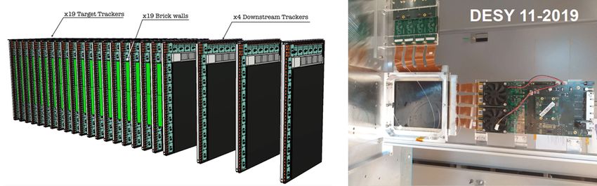
53
   University College London, London, United Kingdom
54
   University of Warwick, Warwick, United Kingdom
55
   Taras Shevchenko National University of Kyiv, Kyiv, Ukraine
a
  Università di Bari, Bari, Italy
b
  Università di Bologna, Bologna, Italy
c
  Università di Cagliari, Cagliari, Italy
d
  Università di Napoli “Federico II”, Napoli, Italy
e
  Associated to Gyeongsang National University, Jinju, Korea
f
  Associated to Petersburg Nuclear Physics Institute (PNPI), Gatchina, Russia
g
  Also at Moscow Institute of Physics and Technology (MIPT), Moscow Region, Russia
h
  Consorzio CREATE, Napoli, Italy
i
  Università della Basilicata, Potenza, Italy
Contents

Executive Summary                                                                                            5
1        The SHiP detector . . . . . . . . . . . . . . . . . . . . . . . . . . . . . . . . . . . . . . .      6
2        Summary of physics performance . . . . . . . . . . . . . . . . . . . . . . . . . . . . . . .         7
2.1        Hidden Sector particles: signal sensitivities . . . . . . . . . . . . . . . . . . . . . . . .      8
2.2        Hidden Sector particles: background studies . . . . . . . . . . . . . . . . . . . . . . . .        9
2.3        Light Dark Matter searches at SHiP . . . . . . . . . . . . . . . . . . . . . . . . . . . .        10
2.4        Neutrino physics at SHiP . . . . . . . . . . . . . . . . . . . . . . . . . . . . . . . . . .      11
2.5        Muon-flux measurement . . . . . . . . . . . . . . . . . . . . . . . . . . . . . . . . . .         13
2.6        Charm-production in the SHiP target . . . . . . . . . . . . . . . . . . . . . . . . . . . .       14
3        Detector subsystems status and plans . . . . . . . . . . . . . . . . . . . . . . . . . . . . .      16
3.1        Magnetisation of the hadron stopper . . . . . . . . . . . . . . . . . . . . . . . . . . . .       16
3.2        Free-standing muon shield . . . . . . . . . . . . . . . . . . . . . . . . . . . . . . . . .       18
3.3        SND spectrometer magnet . . . . . . . . . . . . . . . . . . . . . . . . . . . . . . . . .         19
3.4        HS spectrometer magnet . . . . . . . . . . . . . . . . . . . . . . . . . . . . . . . . . .        20
3.5        HS vacuum vessel . . . . . . . . . . . . . . . . . . . . . . . . . . . . . . . . . . . . . .      22
3.5.1        Decay volume . . . . . . . . . . . . . . . . . . . . . . . . . . . . . . . . . . . . . . .      22
3.5.2        Spectrometer vacuum section . . . . . . . . . . . . . . . . . . . . . . . . . . . . . . .       23
3.5.3        HS vacuum vessel front- and end-cap . . . . . . . . . . . . . . . . . . . . . . . . . .         24
3.5.4        Vacuum system . . . . . . . . . . . . . . . . . . . . . . . . . . . . . . . . . . . . . .       24
3.6        SND emulsion target . . . . . . . . . . . . . . . . . . . . . . . . . . . . . . . . . . . .       25
3.7        SND target tracker . . . . . . . . . . . . . . . . . . . . . . . . . . . . . . . . . . . . . .    27
3.8        SND muon identification system . . . . . . . . . . . . . . . . . . . . . . . . . . . . . .        28
3.9        SND upstream background tagger . . . . . . . . . . . . . . . . . . . . . . . . . . . . .          30
3.10       HS surround background tagger . . . . . . . . . . . . . . . . . . . . . . . . . . . . . .         31
3.11       HS spectrometer straw tracker . . . . . . . . . . . . . . . . . . . . . . . . . . . . . . .       32
3.12       HS timing detector . . . . . . . . . . . . . . . . . . . . . . . . . . . . . . . . . . . . .      35
3.13       HS split calorimeter . . . . . . . . . . . . . . . . . . . . . . . . . . . . . . . . . . . . .    37
3.14       HS muon system . . . . . . . . . . . . . . . . . . . . . . . . . . . . . . . . . . . . . .        38
3.15       Common detector electronics and online system . . . . . . . . . . . . . . . . . . . . . .         40
3.16       Offline computing . . . . . . . . . . . . . . . . . . . . . . . . . . . . . . . . . . . . . .     41
3.17       Safety implications of SHiP . . . . . . . . . . . . . . . . . . . . . . . . . . . . . . . . .     42
3.17.1       Mechanical and structural safety . . . . . . . . . . . . . . . . . . . . . . . . . . . . .      42
3.17.2       Fire safety . . . . . . . . . . . . . . . . . . . . . . . . . . . . . . . . . . . . . . . . .   42
3.17.3       Electrical safety . . . . . . . . . . . . . . . . . . . . . . . . . . . . . . . . . . . . . .   42
3.17.4       Non-ionising radiation safety . . . . . . . . . . . . . . . . . . . . . . . . . . . . . . .     42
3.17.5       Chemical safety . . . . . . . . . . . . . . . . . . . . . . . . . . . . . . . . . . . . . .     43
4        Road map . . . . . . . . . . . . . . . . . . . . . . . . . . . . . . . . . . . . . . . . . . .      44
5        Cost estimates . . . . . . . . . . . . . . . . . . . . . . . . . . . . . . . . . . . . . . . . .    46
6        Status of the SHiP Collaboration . . . . . . . . . . . . . . . . . . . . . . . . . . . . . . .      48

                                                       4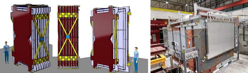
Executive Summary
The SHiP Expression of Interest was submitted to the SPSC in October 2013 [3], resulting in a recom-
mendation to form a collaboration and to prepare a Technical Proposal (TP) for the detector and the
experimental facility. The TP was submitted to the SPSC in April 2015 [4]. Under the initiative and ex-
perimental guidance of the SHiP Collaboration, the TP was complemented by the SHiP Physics Case [5],
prepared by a large group of theorists. The SHiP TP was reviewed by the SPSC up to January 2016. In
response to the review, SHiP produced an addendum that demonstrated the advantage of operating SHiP
at the SPS as compared to facilities elsewhere, and a detailed road map and resources required for the
next study phase [6]. The SPSC concluded with a recommendation for SHiP to proceed with a three-
year Comprehensive Design Study for both the detector and facility [7]. The CERN Research Board and
the CERN management approved the recommendation in March 2016. The study of the SHiP detector
and the Beam Dump Facility (BDF) were included as R&D projects under the Physics Beyond Collider
forum (PBC) [8], with the further recommendation to submit an advanced proposal to the European
Particle Physics Strategy Update (EPPSU) and an evaluation of the physics prospects by the PBC.
       The Comprehensive Design Study (CDS) phase for the SHiP detector has consisted of a broad-
gauged re-optimization of the overall detector configuration, and of the individual components, in re-
sponse to the studies and efforts to improve the physics performance and to extend the physics pro-
gramme. The simulation framework has evolved substantially with the inclusion of all relevant physics
models using the PYTHIA and GENIE event generators, and a detailed description and response of all
sub-detector systems in GEANT. The CDS phase has also included detailed technological and engin-
eering studies, and beam tests of prototypes of all components. Dedicated measurements of the muon
spectrum, with a prototype of the SHiP beam dump target, and charm production have been performed
to validate the physics simulation.
       The outcome of the CDS study has been documented in the proposals for SHiP [9] and BDF [10],
submitted to the EPPSU, in the SHiP Progress Report [1], submitted to the SPSC in January 2019, and
in the BDF Yellow Report [2], submitted for publication by the BDF team in December 2019. The SHiP
Progress Report and the BDF Yellow Report are comprehensive records of the extended physics oppor-
tunities, the re-optimization performed during the CDS phase, the technological studies, prototyping and
beam tests, and the preliminary designs of all components involved in the detector and in the facility.
       In parallel with these documents, the PBC forum has prepared summary documents with the evalu-
ation of the technological and the scientific prospects [11,12], ranking SHiP as a mature and competitive
project ready for implementation. The SHiP/BDF project was extensively discussed at the Open EPPSU
Symposium in Granada in May 2019 [13], and drew significant attention and support as a major potential
player in the search for Feebly Interacting Particles. The EPPSU Physics Briefing Book [14] reflects very
well these favourable conclusions.
       The CDS report herein is a summary of the current status of the physics and the detector with
focus on the challenges and the plans for the preparation of the Technical Design Reports (TDR). The
CDS work has generated a detailed understanding of the road map and the costs for both the detector
R&D and the construction, presented at the end of the document. For the TDRs the Collaboration aims
at taking the developments and the engineering through a Module-0 phase for all subsystems, aiming at
executive design level, to be able to proceed with construction in a timely fashion in parallel with the
construction of the BDF, should the project be approved after submission of the BDF and the detector
TDRs. Assuming approval of the TDR phase in 2020, the delivery of the reports is foreseen for end of
2022 for the BDF, and end of 2023 for the SHiP detectors.
       As demonstrated in this document, the SHiP Collaboration is ready to commence preparation
of TDRs and expects an approval of this phase after the finalisation of the full EPPSU process. Timely
approval of the TDR phase is critical in order to be in position to seek funding for a seamless continuation
of the SHiP activities.

                                                     5
Figure 1: Overview of the SHiP experiment as implemented in the full simulation.

1   The SHiP detector
The current layout of the SHiP experimental setup is shown in Figure 1. The setup consists of a high-
density proton target [15, 16], followed by a hadron stopper and an active muon shield [17], which
sweeps away the muons produced in the beam dump in order to reduce the initial flux by six orders
of magnitude in the detector acceptance. The target is made of blocks of a titanium-zirconium doped
molybdenum alloy (TZM) in the core of the proton shower, followed by blocks of pure tungsten with a
tantalum cladding. The total target thickness is twelve interaction lengths. The five metres long hadron
stopper absorbs hadrons and electromagnetic radiation emerging from the target. A magnetic coil has
been incorporated into the hadron stopper to magnetise the iron shielding blocks. This magnet serves as
the first section of the active muon shield. The rest of the muon shield consists of 30 m of free-standing
warm magnets located in the underground experimental hall, totalling 1300 tonnes of magnetic mass.
       The SHiP detector consists of two complementary apparatuses, the scattering and neutrino detector
(SND) and the hidden sector (HS) decay spectrometer. The SND will search for light dark matter (LDM)
scattering and perform neutrino physics. It also provides normalisation of the yield for the hidden particle
search. It consists of a precision spectrometer located inside a single long dipole magnet with a field
of 1.2 T, followed by a muon identification detector. The precision spectrometer is a hybrid detector
composed of modules with alternating layers of absorber, nuclear emulsion films and fast electronic
target trackers (TT). The absorber mass totals ∼8 tonnes.
       The HS decay spectrometer aims at measuring the visible decays of HS particles by reconstructing
their decay vertices in a 50 m long decay volume of a pyramidal frustum shape. In order to eliminate the
background from neutrinos interacting in the decay volume, it is maintained at a pressure of < 10−2 bar.
The decay volume is followed by a large spectrometer with a rectangular acceptance of 5 m width and
10 m height. The main element is the spectrometer straw tracker (SST) designed to accurately reconstruct
the momenta and the decay vertex, mass and impact parameter of the hidden particle trajectory at the
proton target. The spectrometer dipole magnet is a conventional magnet with a total field integral of
about 0.65 Tm.
       An electromagnetic calorimeter (ECAL) and a muon detector provide particle identification which
is essential in discriminating between the very wide range of HS models. The ECAL is a lead sampling
calorimeter, consisting of two parts which are mechanically separated in the longitudinal direction, each
part being equipped with a high spatial resolution layer to reconstruct decays of axion-like particles to
two photons. The muon system consists of four stations interleaved by three muon filters.
      The key feature of the HS decay spectrometer design is to ensure efficient suppression of different
backgrounds. A dedicated timing detector (TD) with ∼100 ps resolution provides a measure of time

                                                     6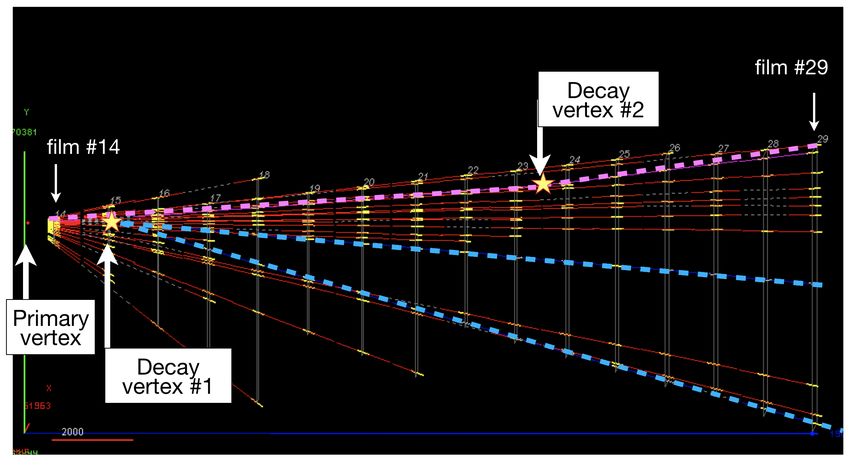
coincidence in order to reject the combinatorial background. The decay volume is surrounded by the
background taggers: the SND upstream background tagger (UBT) and the surround background tag-
ger (SBT) that instruments the decay volume walls. The taggers identify neutrino- and muon-induced
inelastic interactions in the material of the SND detector and in the decay volume walls, which may pro-
duce long-lived neutral particles, V 0 s, decaying in the decay volume and mimicking HS signal events.
       The muon shield and the SHiP detector systems are housed in an ∼120 m long underground ex-
perimental hall at a depth of ∼15 m. To minimise the background induced by the flux of muons and
neutrinos interacting with material in the vicinity of the detector, no infrastructure is located on the sides
of the detector, and the hall is 20 m wide along its entire length.

2   Summary of physics performance
The physics performance of the SHiP experiment is anchored in an extremely efficient and redundant
background suppression. Two detector systems provide a complementary search. The HS detector aims
at fully reconstructing the widest possible range of decay modes, including particle identification, to
ensure a model independent search for hidden particles. The SND system is optimised for scattering
signatures of LDM and neutrinos. A detailed description of the SHiP physics case can be found in
Ref. [5].
       In addition to improving present constraints by several orders of magnitude for various HS chan-
nels, SHiP can distinguish among the different models, and, in large part of the parameter space, measure
parameters that are relevant for cosmology and model building. These features make the SHiP exper-
iment a unique discovery tool for Hidden Sector particles. Moreover, together with the direct search
for LDM, and neutrino physics, SHiP represents a wide scope general purpose fixed target experiment.
Further proposals for using the same beam facility in parallel have been presented independently [18,19].

Figure 2: SHiP’s sensitivity to dark photons (top-left), dark scalars (top-right), axion-like particles
coupled to fermions (bottom-left) and to photons (bottom-right). References to the current constraints
shown and more details can be found in [12].

                                                      7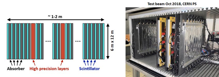
2.1   Hidden Sector particles: signal sensitivities
Illustrative examples of SHiP’s physics potential are the sensitivities to dark photons (DP), dark scalars
(DS), and axion-like particles (ALP) coupled to fermions and photons shown in Figure 2, and to heavy
neutral leptons (HNL) in Figure 3. The sensitivities have been determined using SHiP’s full MC simu-
lation framework (FairShip) and by following the benchmark recipes established in the PBC forum [12],
and are based on collecting 2 × 10²⁰ protons on target (PoT), which appears realistic in five years of
nominal operation according to the BDF beam extraction studies. In case of discovery, SHiP is capable
of measuring parameters and identifying the underlying models. For instance, the left plot of Figure 4
shows that SHiP may distinguish between Majorana-type and Dirac-type HNLs in a significant fraction
of the parameter space by detecting lepton number violating or conserving decays [20]. If the mass
splitting between the HNLs is small, the right plot shows that it may also be possible to resolve HNL
oscillations as a direct measurement of the mass splitting between HNLs.

Figure 3: SHiP’s sensitivity to heavy neutral leptons. References to the current constraints shown and
more details can be found in [12].

Figure 4: Left: lower bound on the SHiP sensitivity to HNL lepton number violation (black dashed line).
Reconstructed oscillations between the lepton number conserving and violating event rates as a function
of the proper time for a HNL with the parameters MN = 1 GeV/c2 , |U |2µ = 2 × 10⁻⁸ and mass splitting
of 4 × 10⁻⁷ eV. Both figures are from Ref. [20].

                                                    8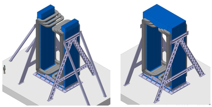
2.2   Hidden Sector particles: background studies
In order to maximise SHiP’s sensitivity to HS particles, the background should be reduced to a negligible
level. In addition, the redundancy of the selection criteria will allow determining the background directly
from data and, in case of signal evidence, to perform cross checks that minimise the probability of false
positives. The broad range of signals to which the SHiP experiment is sensitive can be classified into two
main categories: fully and partially reconstructed decays. The former category refers to decays where
there are at least two charged particles and no invisible final state particles, examples are HNL → µ± π ∓
and HNL → µ± ρ∓ (→ π ∓ π 0 ). The latter category refers to decays with at least two charged particles
and at least one invisible particle in the final state, e.g. HNL → µ± µ∓ ν. In all cases, the experimental
signature consists of an isolated vertex, pointing back to the target. A common set of loose selection
criteria are applied to all HS searches to suppress the background (Table 1).

            Requirement                                                        Value
            Track momentum                                                  > 1.0 GeV/c
            Track pair distance of closest approach                           < 1 cm
            Track pair vertex position in decay volume                 > 5 cm from inner wall
            Impact parameter w.r.t. target (fully reconstructed)              < 10 cm
            Impact parameter w.r.t. target (partially reconstructed)         < 250 cm
Table 1: Pre-selection criteria used for the background rejection and the sensitivity estimate in the ana-
lysis of Hidden Sector particle decays.

      There are three main sources of background that can mimic the signature of Hidden Sector particles:
random muon combinatorial, muon inelastic scattering and neutrino deep inelastic scattering. The back-
ground from cosmics has been proven to be negligible.
• Random muon combinatorial: The expected rate for muons that survive the muon shield or back-
scatter in the cavern and traverse the SHiP spectrometer is 26.3±3.6 kHz. A sample of fully simulated
muon combinatorial events was used to study this background. This sample was also complemented
with a fast simulation based on Generative Adversarial Networks [21], which allowed producing a large
sample of muons with the same kinematic and topological properties as obtained from the full simulation.
After applying the acceptance and selection cuts listed in Table 1, we expect about 109 pairs of muons
for the partially reconstructed topology in the lifetime of the experiment. These are suppressed to the
level of 10−2 muon pairs by requiring the muons to coincide in a time window of 340 ps, corresponding
to > 2.5 times the time resolution of the HS timing detector. Redundancy and/or further rejection of the
muon combinatorial background can be obtained by using veto information from the surround and the
upstream background taggers.
• Muon inelastic: Muons interacting inelastically in the floor and walls of the cavern, and in the material
upstream of the vacuum vessel, can produce particles that enter the decay volume and mimic the signal.
We expect about 2 × 10⁸ deep inelastic scattering (DIS) muons in the proximity of the vacuum vessel for
2 × 10²⁰ PoT. Samples of background corresponding to the equivalent number of protons on target have
been generated. No events remain after applying the pre-selection in Table 1 and veto information from
the surround and the upstream background taggers. To further investigate the background suppression
we assumed that the background taggers’ veto and the pointing criteria factorize. With this assumption
we have set an upper limit of 6 × 10⁻⁴ expected background events for 2 × 10²⁰ PoT.
• Neutrino deep inelastic: The dominant source of this background comes from neutrino inelastic scat-
tering in the proximity of the decay volume, roughly corresponding to 3.5×10⁷ interactions from 2×10²⁰
PoT. In order to avoid irreducible background from neutrinos interacting with the air molecules inside
the vessel, a level of vacuum below 10−2 bar is necessary. The background from neutrino scattering in
the floor and the walls of the cavern was studied and found to be negligible. A large sample, corres-

                                                    9
ponding roughly to seven times the planned proton yield of 2 × 10²⁰ PoT was generated. By applying
the selection cuts listed in Table 1 together with the background tagger veto information and timing,
we expect < 0.1 background events for the fully reconstructed signal and 6.8 background events for the
partially reconstructed signal. This background consists of photon conversions in the material. It can be
easily eliminated by requiring an invariant mass of the pair to be larger than 100 MeV/c2 .
To summarise, as shown in Table 2, the SHiP experiment can be considered a zero-background
experiment with a high level of redundancy to efficiently suppress the background for a broad spectrum
of searches for visible decays of Hidden Sector particles.
Background source Expected events
Neutrino background < 0.1 (fully) / < 0.3 (partially)
Muon DIS (factorisation) < 6 × 10⁻⁴
Muon combinatorial 4.2 × 10⁻²
Table 2: Expected background in the search for HS particle decays at 90% CL for 2 × 10²⁰ protons on
target after applying the pre-selection, the timing, veto, and invariant mass cuts. The neutrino background
is given separately for fully and partially reconstructed background modes.
2.3 Light Dark Matter searches at SHiP
SHiP can probe existence of LDM (χ) by detecting the electromagnetic showers initiated by the recoil
electrons coming from elastic scattering of LDM in the SND. The SND emulsion cloud chamber (ECC)
bricks, interleaved with the SND target tracker planes, act as sampling calorimeters with five active layers
per radiation length, X0 , and a total depth of 10 X0 . The configuration allows reconstructing a sufficient
portion of the shower produced by the recoil electron to determine the particle angle and energy. In
addition, the micro-metric accuracy of the nuclear emulsions provide crucial topological discrimination
of LDM interactions against neutrino-induced background events.
Neutrino events with only one reconstructed outgoing electron at the primary vertex constitute
background in the LDM searches, mimicking the signature χe− → χe− . The GENIE [22] Monte Carlo
generator, interfaced with FairShip, has been employed for a full simulation to provide an estimate of the
expected background for 2 × 10²⁰ PoT.
The resulting background estimate for the different categories of neutrino interactions for 2 × 10²⁰
PoT is reported in Table 3. The dominant background contribution arises from νe quasi-elastic scattering
(νe n → e− p, with the soft proton unidentified) and from topologically irreducible sources, i.e. νe (ν̄e )
elastic and ν̄e quasi-elastic scattering (ν̄e p → e+ n).
Signal events have been simulated with the help of the MadDump software [23], and assuming
LDM pair-production (χχ̄) in the prompt decays of DP. In the considered DP mass range of MA0 ∼
O(1 GeV/c2 ), only contributions from the decay of light mesons (π, η, ω) and proton bremsstrahlung
have been included. Prompt-QCD and heavier Drell Yan-like production mechanisms have been proven
to be negligible. Assuming a benchmark scenario with relevant theory parameters corresponding to a
dark coupling constant of αD = 0.1 and an LDM mass of Mχ = MA0 /3, and a total of ∼ 800 neutrino
background events, the SHiP 90% CL sensitivity is computed in the plane (Mχ , Y = 2 αD (Mχ /MA0 )4 ),
where is the dark photon coupling. Figure 5 compares the SHiP sensitivity with the current ex-
perimental constraints and the thermal relic abundances, showing an excursion of about one order of
magnitude, and competitive limits in the considered region. The ultimate SHiP sensitivity for zero back-
ground is also shown.
10νe ν̄e νµ ν̄µ all
Elastic scattering 81 45 56 35 217
Quasi - elastic scattering 245 236 481
Resonant scattering 8 126 134
Deep inelastic scattering - 14 14
Total 334 421 56 35 846
Table 3: Estimate of the neutrino backgrounds in the Light Dark Matter search with the SND for an
integrated proton yield of 2 × 10²⁰ PoT.
Figure 5: SHiP exclusion limits at 90% CL as a function of the LDM mass Mχ , compared to the current
experimental limits by NA64 [24] and BaBar [25] (grey shaded area) and the predicted thermal relic
abundances. The coupling is provided as Y = 2 αD (Mχ /MA0 )4 .
2.4 Neutrino physics at SHiP
The nuclear emulsion technology combined with the information provided by the SND muon identific-
ation system makes it possible to identify the three different neutrino flavours in the SND detector. The
neutrino flavour is determined through the flavour of the primary charged lepton produced in neutrino
charged-current interactions. The muon identification is also used to distinguish between muons and
hadrons produced in the τ decay and, therefore, to identify the τ decay channel. In addition, tracking in
the SND magnetic spectrometer will allow for the first time to distinguish between ντ and ν τ by meas-
uring the charge of τ decay products. The charge of hadrons and muons is measured by the Compact
Emulsion Spectrometer, the Muon Tracker, and by the muon identification system. The electron decay
channel of the τ lepton is not considered for the discrimination of ντ against ν τ .
The neutrino fluxes produced at the beam dump were estimated with FairShip, including the con-
tribution from cascade production in the target. The number of charged-current (CC) DIS interactions
in the neutrino target is evaluated by convoluting the generated neutrino spectrum with the cross-section
provided by GENIE. The expected number of CC DIS in the target of the SND detector is reported in
Table 4, and the corresponding energy spectra are shown in Figure 6.
By combining the overall neutrino CC DIS interaction yield in the target with the detection effi-
ciencies, it is possible to estimate the expected number of ντ and ν τ interactions observed in the different
11hEi CC DIS
[GeV] interactions
Nνe 59 1.1 × 10⁶
Nνµ 42 2.7 × 10⁶
Nντ 52 3.2 × 10⁴
Nν e 46 2.6 × 10⁵
Nν µ 36 6.0 × 10⁵
Nν τ 70 2.1 × 10⁴
Table 4: Expected CC DIS interactions in Figure 6: Momentum spectra of muon, electron and tau
the SND assuming 2 × 10²⁰ PoT. neutrinos undergoing DIS in the SND target.
hEi CC DIS Charm frac.
[GeV] w. charm prod [%]
Decay channel ντ ντ Nνµ 55 1.3 ×10⁵ 4.7
τ →µ 1200 1000 Nνe 66 6.0 ×10⁴ 5.7
τ →h 4000 3000 Nν µ 49 2.5 ×10⁴ 4.2
τ → 3h 1000 700 Nν e 57 1.3 ×10⁴ 5.1
Total 6200 4700 Total 2.3 ×10⁵
Table 5: Expected number of ντ and ν τ Table 6: Left: Expected CC DIS neutrino interactions
signal events observed in the different τ with charm production for 2 × 10²⁰ protons on target.
decay channels, except for the τ → eX Right: relative charm production yield per electron and
decays in which the lepton number cannot muon neutrinos CC DIS interaction.
be determined.
decay channels. Since the charge of the electron is not measurable, only an inclusive measurement of ντ
and ν τ is possible in the τ → eX decay channel. Unprecedented samples of about 6000 ντ and 5000 ν τ
detected interactions are expected for 2 × 10²⁰ protons on target, as reported in Table 5.
The expected charm yield with respect to the neutrino CC DIS interactions (σcharm /σCCDIS ) was
estimated using the GENIE generator. The charm fractions are reported in the right column of Table 6
for electron and muon neutrinos.
With 2 × 10²⁰ protons on target, more than ∼2×10⁵ neutrino induced charmed hadrons are expec-
ted, as reported in the central column of Table 6. The total charm yield exceeds the samples available in
previous experiments by more than one order of magnitude. No charm candidate from electron neutrino
interactions was ever reported by any previous experiment.
Therefore all the studies on charm physics performed with neutrino interactions will be improved,
and some channels inaccessible in the past will be explored. This includes the double charm production
cross-section [26, 27] and the search for pentaquarks with charm quark content [28]. Charmed hadrons
produced in neutrino interactions are also important to investigate the strange quark content of the nuc-
12leon. The samples available at SHiP will also allow to significantly constrain the ντ magnetic moment
and test lepton flavour violation in the neutrino sector.
2.5 Muon-flux measurement
The muon-flux, produced in the beam dump, enters quadratically into the derivation of the muon com-
binatorial background, and linearly into the muon inelastic background. For this reasons, confidence in
the background estimates requires validating the simulation with real data. A test beam experiment was
conducted in summer 2018 at the H4 beam-line of the CERN SPS in order to measure the muon spec-
trum with a replica of the SHiP target. While the replica had smaller transverse dimensions than the final
target foreseen for BDF/SHiP, it had the full length to properly include cascade production of particles
decaying to muons. About 3 × 10¹¹ PoT at 400 GeV/c momentum were accumulated in three weeks of
running. Description of the setup can be found in Ref. [1, 29].
Results from the comparison of the momentum and transverse momentum of muons from real
data and from muons simulated with the FairShip simulation software are shown in Table 7 and in Fig-
ure 7 [29]. Overall good agreement provides a solid confidence in using FairShip for future optimisation
of the design of the muon shield and the SHiP detectors. An evident peak from J/ψ → µ+ µ− decays
was also observed in the experimental data according to expectation (Figure 8).
Interval Data MC ratio
5 − 10 GeV/c (1.13 ± 0.02) × 105 (1.12 ± 0.03) × 105 1.01 ± 0.04
10 − 25 GeV/c (2.41 ± 0.05) × 104 (1.85 ± 0.06) × 104 1.30 ± 0.05
25 − 50 GeV/c (4.86 ± 0.10) × 103 (3.76 ± 0.11) × 103 1.29 ± 0.05
50 − 75 GeV/c (10.0 ± 0.2) × 102 (8.0 ± 0.2) × 102 1.25 ± 0.05
75 − 100 GeV/c (3.0 ± 0.06) × 102 (2.5 ± 0.08) × 102 1.21 ± 0.05
100 − 125 GeV/c (1.1 ± 0.02) × 102 (0.9 ± 0.03) × 102 1.15 ± 0.05
125 − 150 GeV/c 21.1 ± 0.4 20.1 ± 7.5 1.05 ± 0.04
150 − 200 GeV/c 6.4 ± 0.1 6.6 ± 0.3 0.97 ± 0.04
200 − 250 GeV/c 0.76 ± 0.02 0.88 ± 0.06 0.89 ± 0.06
250 − 300 GeV/c 0.26 ± 0.01 0.26 ± 0.03 0.99 ± 0.11
Table 7: Number of reconstructed tracks in different momentum bins per 109 PoT per GeV/c for data
and MC. The statistical errors for data are negligible. The uncertainty of 2.1% in data is dominated by
the normalisation to the number of protons on target. For MC the uncertainty is 3.3%, with the main
contribution coming from different reconstruction efficiency in MC compared to data.
Figure 7: Comparison between real data from the H4 test beam and the FairShip simulation for mo-
mentum (left) and transverse momentum (right) of muons.
13Figure 8: Invariant mass of di-muon events recorded at the H4 beam-line test beam, opposite sign muon
pairs in blue (fitted) and same sign muon pairs in purple. An evident peak from J/ψ → µ+ µ− decays is
visible (right peak). The left peak consists of unflavoured ρ, η (0) and ω decaying into two muons.
2.6 Charm-production in the SHiP target
Charmed hadrons are produced either directly from interactions of the primary protons or from sub-
sequent interactions of particles produced in the hadronic cascade showers. As a result, the tau neutrino
yield, as well as the yield of any hidden particle produced by charm decays, are subject to large cor-
rections. Simulations of proton interactions in the SHiP target indicate that the charmed hadron yield is
increased by a factor of 2.3 as a result of cascade
√ production [30]. The available measurement of the
associated charm production per nucleon σcc̄ ( 2mE = 27.4 GeV) = 18.1 ± 1.7 µb [31] was obtained
with a thin target for which the secondary production is negligible.
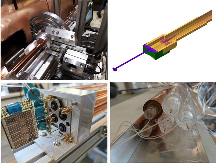
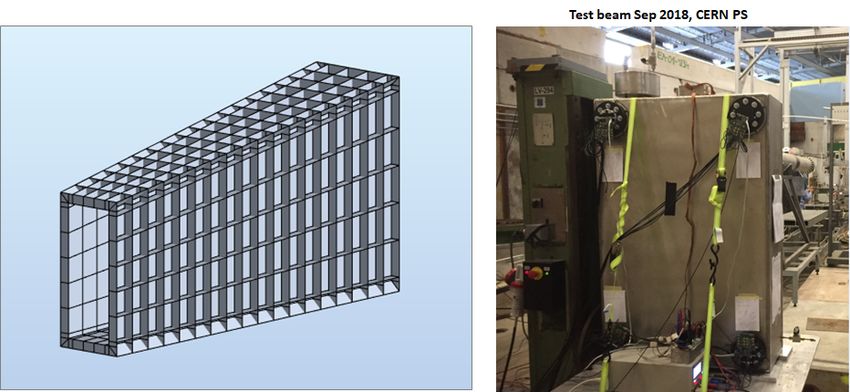
The SHiP Collaboration proposed the SHiP-charm project [32], aiming at measuring the associ-
ated charm production by employing the SPS 400 GeV/c proton beam. This proposal includes a study
of the cascade effect to be carried out using the ECC technique, i.e. slabs consisting of a replica of the
SHiP experiment target [4] interleaved with emulsion films. The detector is a hybrid system, combining
the emulsion technique with electronically read out detectors and a spectrometer magnet to provide the
charge and momentum measurement of charmed hadron decay daughters and the muon identification.
An optimisation run was performed at the H4 beam-line of the CERN SPS in July 2018 with an
integrated number of protons on target of about 1.5×10⁶ . The data has allowed developing reconstruction
software for emulsion which is operating in an environment with significantly higher occupancy, longer
particle flight lengths and smaller angles than in the OPERA experiment. A subset of the data has been
analysed for fine-tuning the new software. Figure 9 shows an example of a double-charm candidate
event that has three vertices: the most upstream is the proton interaction vertex. There are two additional
vertices: one shows a two-prong topology without any charged parent particle while the other one shows
a kink topology. Therefore, the first one is a D0 candidate while the second one is most likely either a D
or a Ds meson. The flight lengths of the neutral and charged charm candidates are 2.1 mm and 12.7 mm,
respectively. The impact parameter of the D0 daughter tracks with respect to the primary proton vertex
are 250 and 590 µm. The kink of the charged charm candidate is 31 mrad and the impact parameter of the
daughter particle to the primary proton vertex is 390 µm. From the measured flight length and average
decay angle, one can infer an estimate of the lifetime of the particle [33]: this gives 1.4 × 10⁻¹² s for
the neutral candidate and 1.3 × 10⁻¹² s for the charged, both consistent with the hypothesis of charmed
hadron decays.
A measurement with a larger statistical sample is planned after the long shutdown LS2 of the
14CERN accelerator complex, with 5 × 10⁷ PoT and a charm yield of about 1000 fully reconstructed
interactions.
Figure 9: A double-charm candidate event produced in proton collisions with the tungsten target recorded
at the H4 charm-production measurement.
153 Detector subsystems status and plans
An overview of the SHiP developments since the TP, and detailed description of the detector components,
are documented in the SHiP Progress Report [1]. In summary the changes since the TP are:
– Introduction of the magnetisation of the hadron stopper as part of improving the muon shield.
– The muon shield optimisation has led to a magnet system which is 35 m in length instead of 48 m,
and has 1300 tonnes of magnetic mass instead of 2900 tonnes.
– The two-magnet system for the SND emulsion target and muon system were replaced with a single
magnet enveloping only the LDM/neutrino target.
– The SND Muon Magnetic Spectrometer was replaced with a conventional muon identification
system, the last section of which constitutes the SND upstream background tagger, and no mag-
netisation.
– The original decay volume, shaped as an elliptical cylinder has been redesigned as a pyramidal
frustum.
– The in-vacuum Straw Veto Tagger has been removed.
– The Spectrometer Straw Tracker stations and the vacuum tank through the spectrometer magnet
have been designed with transverse dimensions of 5 × 10 m2 throughout.
– The Spectrometer Straw Tracker tube diameter has been changed from 10 mm to 20 mm, halving
the total number of tubes.
– The shashlik-based Electromagnetic Calorimeter has been replaced with a calorimeter based on
two different types of active layers, in order to extend its capability to reconstruct two-photon final
states. While most sampling layers are based on scintillating bars, resulting in a significant cost
reduction compared to the shashlik technology, a few high-precision layers are instrumented with
MicroMegas detectors.
– The Hadron Calorimeter has been removed, only the absorber is kept as the first muon filter. The
new Electromagnetic Calorimeter is expected to be capable of providing sufficient identification
for low momentum particles.
– The original muon system with scintillating bars has been replaced by a system based on scintil-
lating tiles with silicon photomultipliers (SiPM) readout to improve the timing performance.
Following these changes, the sections below report on the current strategy and the technology
pursued for each subsystem, including options alternative to the baseline, and the main parameters. The
development path and prototyping which have been undertaken up to now are described. This is followed
by a report on the plans for the TDR phase, outlining the remaining challenges, the proposed solutions,
and the prototypes which will be needed to address the challenges. Detailed timelines are proposed for
all detector subsystems. While the challenges and the main milestones are also relatively clear for the
large common infrastructure items, the design steps and the exact timelines and resources require further
elaboration. Preliminary plans for the construction and installation have been worked out for all systems,
showing that they are compatible with the timeline for the construction of the Beam Dump Facility.
3.1 Magnetisation of the hadron stopper
The detector re-optimization during the CDS phase started from launching an ambitious goal to magnet-
ise the hadron stopper immediately after the proton target. This allows increasing the detector acceptance
by moving the detector closer to the proton target. It reduces significantly the size and weight of the free-
standing muon shield magnets, and improves the overall performance of the muon shield. Taking the
technological limitations into account, the physics simulation has been used to specify the parameters of
the magnetic field.
16Figure 10: Layout of the BDF target bunker, showing the integration of the coil to magnetise the hadron
stopper as the first part of the muon shield.
The baseline design consists of a warm magnet coil integrated into the target bunker iron shielding
(Figure 10). Consequently the coil and the integration of the coil are subject to several strict constraints
related to the radiation exposure, powering, heat extraction, and handling. The CDS design study has
concluded with an extensive report [34] encompassing:
– Optimisation of the magnetic circuit resulting in a final definition of the system:
– optimisation of the yoke layout with realistic assembly from US1010 steel
– simulated field maps for use in physics simulations and for the optimisation and engineering
of the subsequent magnet chain
– hysteresis effects after multiple powering cycles
– magnetic forces of the entire magnetised assembly and interaction with the external/contiguous
shielding
– mapping of the stray field which could potentially influence the target instrumentation
– Preliminary engineering design compatible with the target complex design and the radiation envir-
onment:
– thermal management (consideration of water and gas cooling)
– connections of power cables, sensors etc
– integration of magnetic iron blocks inside the coil for handling reasons
– engineering risks (water leaks, short circuits etc)
– long-term durability and reliability of the designed coil
The study has investigated copper and aluminium coils with liquid and gas cooling. An optimisa-
tion was performed which aimed at producing the largest magnetic field integral provided by the lowest
possible input power which is compatible with cooling by only the surrounding helium gas flow in the
target bunker. A small aluminium prototype coil was built to study the heat extraction. Computational
Fluid Dynamics (CFD) simulations of the target bunker and the planned helium circulation system has
determined the power input limit to 4 kW. The resulting solution for the coil consists of an anodised
aluminium strip coil powered at a current density of 0.45 A/mm2 , and externally cooled by a guided flow
of helium gas through the magnet former of the coil. In these conditions the magnet provides a field
17integral of 7.1 Tm in a magnetic core volume of ∼1.0×1.3× 4.5 m3 . These parameters will be refined
during the TDR phase in the next iteration of the physics optimisation.
The main challenges of the final design concern the large size of the coil (4.5×2 m2 ), proving
the thermal management, reliable connections of services and remote handling, and the manufacturing
technique. The TDR phase foresees the construction of a quarter scale coil assembly which should be
fully tested prior to design and procurement of the full scale magnet. Suppliers for prototyping as well
as for the final production, have been identified for all the necessary components. It is estimated that
∼9 months will be required to design, manufacture and test the prototype. This prototype coil could also
be modified to test a hybrid magnet combining cold-rolled grain-orientated (CRGO) steel with normal
steel.
Considering that the integration of the magnetisation of the hadron stopper is strongly linked to
the BDF Target Complex, it is likely that it will be included in the TDR of the facility.
Figure 11: Left: layout of the free-standing part of the muon shield. Right: electron beam welding in a
vacuum chamber and annealing tests on small scale prototype.
3.2 Free-standing muon shield
The free-standing magnetic muon shield [17, 35] is one of the most critical items for SHiP and, in the
current design strategy, also one of the most challenging subsystems. The baseline design relies on air-
cooled warm magnets made from CRGO steel for an optimal compromise between the field gradient and
the input power. Located behind the proton target hadron stopper, the magnets accumulate a limited radi-
ation dose. The CDS phase has included a full re-optimisation of the magnetic configuration taking into
account the upstream magnetisation of the hadron stopper and advanced technology studies. The tech-
nology studies indicate that it should be possible to assume an average field gradient of 1.7 T including
the magnetic core packing factor. As previously, the optimisation of the geometry has been performed
with Machine Learning using a Bayesian optimisation algorithm and fully simulated muons from the
proton target by GEANT. Under the assumption that the muon shield is composed of six magnets whose
geometry is described by a total of 42 parameters, the algorithm simultaneously minimises the muon
background rate in the HS spectrometer and the total mass of the shield magnet yokes.
In parallel, the CDS phase has successfully accomplished a first iteration of the engineering as-
pects:
– Optimal smooth field geometry from the optimisation of the magnetic shield is approximated with
cuboid-shaped modules.
18– Effects on the magnetic properties of the CRGO steel and mitigation of the assembly of the CRGO
steel sheets.
– Structural engineering for the assembly of whole magnets.
– Investigation of a technology for the coils.
– Evaluation of thermal management and magnetic forces.
– Assembly sequence
The current design (Figure 11 left) consists of about 600 individual packs of sheets with 50 mm
thickness, the largest with transverse dimensions of 6.6×3.8 m2 and weighing about 8 tonnes. In total,
the muon shield has an overall weight of about 1300 tonnes. The total sheet cutting length is about
2000 km. The baseline for the coil consists of 9 mm isolated stranded copper wire consolidated using an
elastic compound. A table-size prototype has already been constructed and tested.
The main challenges concern the assembly technique of the CRGO steel sheets, guaranteeing the
quality and the geometric precision to better than a millimetre, and the time required for the production.
Two options have been pursued: electron-welding which can achieve a welding depth of up to 50 mm
but requires a large vacuum chamber, and laser welding which is limited to < 25 mm. The heating from
welding degrades the magnetic properties of CRGO steel. At the same time, deformation as a result of
heating and manipulation may influence the packing factor that can be achieved. Promising results in
restoring the magnetic properties by annealing at >600 ◦ C have been achieved (Figure 11 right). It is also
expected that the degradation of the magnetic properties due to the heating from welding the joints is
inversely proportional to the size of the magnet, bringing the effect down by a factor 30 to 50 for the real
size magnets as compared to the prototypes studied.
As part of the TDR phase, a mid-size 1.3 × 2.0 m2 prototype is in preparation to further invest-
igate the mechanical quality of the long welded joints, mechanical stability and packing factor, and the
magnetic performance with a realistic module-to-weld size ratio. Both electron and laser welding will be
tested. This work is also aimed at determining details about the mechanical engineering, and procedures
for transport, assembly and installation. The first iteration has also shown that the structure supporting
the magnets on the experimental cavern floor contributes with a significant load which must be taken
into account in the civil engineering. This will also include a proper structural modelling of the complete
assembly to study seismic actions and mitigation.
The TDR phase will also pursue a more conservative approach by performing an optimisation of a
muon shield from a high-quality magnetic steel (e.g. ARMCO steels) which allows constructing it with
thick iron sheets.
The final decision will also depend on whether, during the TDR phase, companies are identified
which are capable of manufacturing the CRGO steel option. For the procurement of appropriate CRGO
steel, several sources have already been identified, and samples have been obtained for testing and for
the first prototype.
3.3 SND spectrometer magnet
Following the re-optimisation of the muon shield it has been possible to determine more accurately the
volume available for the SND. A significant effort has been put on designing the SND spectrometer
magnet adapted to this envelope which at the same time maximises the aperture available to the detector
(Figure 12). The main challenges of the magnet are a 10 m3 volume magnetised with a field gradient
of at least 1.2 T at an acceptable power consumption, and a low stray field to avoid influencing the
deflected muon flux. Furthermore, the emulsion system requires that the thermal management of the
detector volume respects the operating limit at a temperature of 18 ◦ C and that the magnet can be opened
regularly for the emulsion film replacements. The complete procedure to replace the emulsion should
take no more than a day.
19Figure 12: Layout of the SND spectrometer magnet, showing the opening mechanism for the replacement
of the emulsion films.
A comprehensive design including the magnetic, electrical, thermal and structural aspects has been
elaborated during the CDS phase. It is based on a water-cooled warm magnet. Both a coil of copper and
aluminium have been evaluated. A copper conductor with a bore-hole for the water cooling has been
selected as the baseline option. The 356 tonnes iron yoke is built from soft steel. At a current density of
3.2 A/mm2 and an excitation current of ∼10 kA, the total power consumption is ∼ 1 MW. The magnet
design is extensively described in Ref. [36]
A preliminary solution for the implementation of the opening and closing mechanism has been
developed which relies on opening one of the side walls of the yoke by a hydraulic system with the help of
floor rails. The finalisation is planned for the TDR phase, potentially including prototyping. The strategy
for thermal management of the detector volume will need to be simulated and consolidated together with
more information on the dedicated cooling system for the SND target tracker. The manufacturing and
construction have to be addressed in detail during the TDR phase. It is estimated that three years will be
sufficient for the TDR phase.
A super-ferric magnet, possibly cryogen free, would significantly reduce the power consumption,
while respecting the space constraints for the coils. A study is currently being launched in the CERN
TE/MSC group and will be pursued during the TDR phase.
3.4 HS spectrometer magnet
The SHiP HS spectrometer magnet [37] is based on a warm normal conducting magnet. It is required to
have a physics aperture of 5 × 10 m2 and provide a vertical bending power of about ∼0.65 Tm over the
distance between the upstream and the downstream tracking stations. As the magnet aperture is limited in
the horizontal plane by the region cleared from the beam-induced muon flux, the choice of the horizontal
field orientation stems from the fact that it means a shorter field gap. In addition it has the critical function
of providing structural support to the vacuum vessel, as discussed below in Section 3.5.2.
The baseline design for the coils consists of a square-shape hollow aluminium conductor with
transverse dimensions of 50 × 50 mm2 and a bore hole of 25 mm for water cooling, as for the LHCb
dipole [38]. The idea is to profit from the experience with the manufacturing of the LHCb coils. First
investigations indicate that the tooling developed, which is currently stored at CERN, can be adapted.
The yoke is built from a pack of 50 mm thick sheets of AISI 1010 steel. The pack is assembled in a
brick-laying fashion around the corners. In terms of aperture, 100 mm has been reserved all around the
20You can also read