SODIUM-COOLED 4th-GENERATION
←
→
Page content transcription
If your browser does not render page correctly, please read the page content below
FROM RESEARCH TO INDUSTRY

                                   Nuclear Energy Division

                              th
                              4 -GENERATION
                              SODIUM-COOLED
                              FAST REACTORS
                              THE ASTRID
                              TECHNOLOGICAL
                              DEMONSTRATOR

                                                       DECEMBER 2012

SUSTAINABLE RADIOACTIVE WASTE MANAGEMENT ACT OF JUNE 28, 2006:
RESULTS OF RESEARCH CARRIED OUT ON THE SEPARATION AND
TRANSMUTATION OF LONG-LIVED RADIOACTIVE ELEMENTS, AND ON THE
DEVELOPMENT OF A NEW GENERATION OF NUCLEAR REACTORS

                                                                       1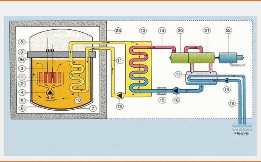
4th GENERATION
SODIUM-COOLED
FAST REACTORS
THE ASTRID
TECHNOLOGICAL
DEMONSTRATOR

                 1
2
FOREWORD

The objective of the Generation IV International Forum (GIF), in        Finally, VHTR is a thermal spectrum system. The specificity of
which France is actively involved, is to prepare the future nuclear     this concept lies in its high temperature operation (up to 1,000°C
sector in an international framework by jointly developing the          for the coolant) for applications other than the production of
R&D of 4th generation reactors, based on clearly identified             electricity.
objectives:
                                                                        Therefore, among the six concepts selected by the GIF, only four
   achieve sustainable development of nuclear energy by                will or can operate in fast neutron spectrum (SFR, GFR, LFR and
    optimising the use of natural uranium resources and by              MSR) and have intrinsic characteristics (associated with a closed
    reaching the highest levels of nuclear safety;                      fuel cycle) suitable for sustainable development of nuclear
                                                                        energy.
   minimise the production of the most radioactive waste, in
    particular long-lived waste;
   ensure high resistance to nuclear proliferation;
   develop applications of nuclear energy for other uses than          EUROPE’S CHOICES
    production of electricity.
                                                                        European countries are currently maintaining very different
After an analysis phase carried out jointly by the founding             positions concerning the part that the nuclear sector must play in
partners, the GIF selected six concepts of nuclear reactors and         their energy mix, whether in the medium or the long run.
their cycles4 which exhibited the most promising potentials to          However, several European countries and the European
achieve the abovementioned objectives:                                  Commission have recognised that nuclear energy will necessarily
                                                                        play a significant part in the way of responding to the energy
   SFR: Sodium-cooled Fast Reactor;
                                                                        demand in a context of greenhouse gas reduction. The SET Plan5,
   GFR: Gas-cooled Fast Reactor;                                       proposed by the European Commission in November 2007 and
                                                                        adopted by the European Union Member States in
   LFR: Lead-cooled Fast Reactor;                                      February 2008, considers that it is essential to start, within the
   SCWR: Supercritical Water-cooled Reactor;                           next ten years, the construction of a new-generation reactor
                                                                        demonstrator for sustainable nuclear energy. Although certain
   VHTR: Very High Temperature Reactor;                                countries have decided to stop using nuclear energy, the
   MSR: Molten Salt Reactor.                                           Fukushima accident does not throw back into question the
                                                                        fundamental elements expressed in the SET Plan.
Except for the VHTR, all these systems operate in closed cycle,
that is to say that they are based on recycling of reusable             The European nuclear technology development sector, gathered
materials, in particular plutonium. The first three systems among       in the SNETP6 platform, defined its strategy and priorities in its
the six ones are characterised by the fact that they are fast neutron   “Vision Report” published in September 2007 and detailed in its
reactors (FR). These are the SFR, GFR and LFR systems which             “Strategic Research Agenda” published in May 2009: nuclear
differ by their coolants: sodium for the SFR system, gas for the        fission will bring a massive, carbon-free and sustainable
GFR system and lead for the LFR system.                                 contribution to the European energy mix by relying on fast
                                                                        neutron reactors (FR). The SFR technology is considered as the
The SCWR is a reactor whose technology is derived from that of          reference system, while two alternatives will have to be explored
pressurised water reactors (PWR) and it uses a particular coolant:      in the long run: the GFR and LFR technologies:
supercritical water. Obtaining a spectrum of fast neutrons in such
a concept involves significant difficulties (thermal hydraulics,        In line with the recommendations of the SET Plan, the SNETP
coupling with the neutronic systems and stability of the reactor)       platform launched the ESNII (European Sustainable Nuclear
and most of the studies performed on the SCWR within the GIF            Industrial Initiative), which gathers industrialists and R&D
are now focused on a version with thermal neutron spectrum.             organisations around this action plan.

MSR will appear in a more distant future and, in theory, they can
be derived into versions operating in fast or thermal spectrum.

                                                                        5 – SET Plan: Strategic Energy Technology Plan http://ec.europa.eu/energy/
                                                                        technology/set_plan/set_plan_en.htm
4 – A Technology Roadmap for Generation IV Nuclear Energy Systems,
December 2002 - US-DoE and GIF.                                         6 – Sustainable Nuclear Energy Technology Platform. www.snetp.eu

                                                                                                                                                     3
FOREWORD

         FAST REACTOR TECHNOLOGIES SELECTED BY THE SNETP EUROPEAN PLATFORM

FRANCE’S POSITION                                                           –   Helium is optically transparent, unlike liquid metals; this
                                                                                makes in-service inspection and repairability easier;
France has joined the European strategy. The more specific
analysis carried out in France led to the following conclusions:
                                                                            –   Helium is chemically inert, contrary to sodium which
   France has brought a major contribution to the development                  reacts with air and water;
    of SFRs and intends to rely on its large experience to develop
    this system with the purpose of achieving the allocated                 –   Helium has a very low neutral impact; in case of loss of
    objectives. Furthermore, this experience is a significant                   coolant, the resulting reactivity effect is very small.
    heritage of intellectual property and provides our country and
    its industrialists with a competitive advantage.                       On the other hand, gas has drawbacks:
   There is a strong connection between the technological                  –   Its low density and low calorific value require the use of
    maturity of a process and nuclear safety. As a matter of fact,              a pressurised primary circuit. During an accident leading
    technological control associated with significant experience                to a loss of the coolant, the thermal inertia of the reactor
    feedback contributes to guaranteeing the safety level of a                  will be very limited in comparison to the inertia of liquid
    system. Therefore, among the 4th generation fast reactor                    metal cooled reactors. As a matter of fact, the decay heat
    systems, only the SFR has a sufficient knowledge base to                    removal capacity and the associated safety demonstration
    meet the technical and operational expectations of                          still remain a significant problem for the demonstration of
    4th generation systems in the short and medium runs. The                    feasibility of GFRs, in particular with the post-Fukushima
    economic conditions of the development of such systems still                type requirements;
    remain to be assessed. They will have to be examined in the
    overall context of a fleet in which, at the beginning, 3rd and          –   In order to have a sufficient margin in terms of core
    4th generation reactors will be used simultaneously in order to             integrity as a measure for prevention of severe accidents,
    produce electricity at the best price while fulfilling a strategy           it is necessary to use a fuel and refractory cladding and
    intended to implement sustainable management of                             structure materials able to withstand high temperatures.
    radioactive waste produced by used fuels based on the                       This is also a technological obstacle that still remains to
    concept of closed cycle applied in its entirety. The other                  be cleared;
    systems involve much more significant uncertainties, as some
    major technological obstacles still have not been cleared.
                                                                            –   Gas has a lower heat extraction capability, which requires
   The GFR system is highly attractive since the use of coolant                to reduce the power density of the core by a factor of 2 to
    gas, in particular helium, removes the difficulties related to              3 in comparison to the power density of liquid metal
    the use of a liquid metal such as sodium or lead:                           cooled fast reactors; this means drawbacks in terms of
                                                                                saving, as it requires a significant quantity of fuel.

4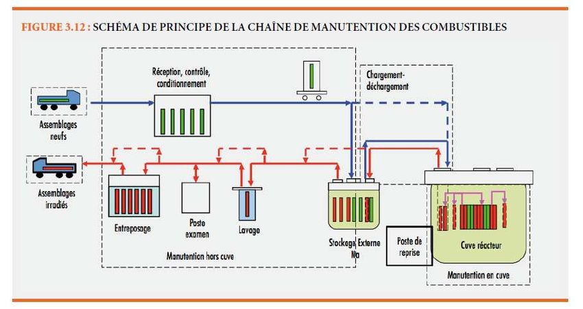
CEA | DECEMBER 2012

   The main advantage of the lead coolant in comparison to                 and repair in the presence of highly radioactive salts). It is to
    sodium is its low chemical reactivity with air and water. The           be noted that the operation and safety of an MSR strongly
    main drawbacks of lead are its toxicity, its temperature                depend on chemical processes whose control is very complex
    ranges (risk of blockage due to freezing of the lead), and its          and which are still poorly known, thus leading to risks of
    density which is detrimental to the resistance of the reactor in        leakage. Another problem concerns the coupling of these
    case of earthquake. But the main technological obstacle of              chemical processes with the neutron equipment of the core or
    lead concerns the development of structure materials able to            with the mechanisms of degradation of materials under
    resist lead corrosion.                                                  irradiation. The CNRS is performing the main part of the
                                                                            studies on MSR in France. Within the GIF, this concept is
   Finally, in its principle, MSR is an interesting concept since          currently studied and supported only by France and Euratom,
    the fuel is in a liquid form mixed with the coolant. The                through a “Memorandum of Understanding” (MoU), and the
    number of technological obstacles to be cleared is such that            “system” agreement still remains to be negotiated.
    this type of system will certainly not be able to enter service
    before the second half of this century, in particular given the      During the Committee on Atomic Energy of 17 March 2005
    quantity of innovations to be achieved to comply with the            concerning future nuclear systems, the Ministers for Industry and
    safety objectives considered. Beyond the questions related to        Research acknowledged the fact that, in the current state of
    on-line fuel reprocessing, materials able to withstand salt          knowledge, there is a very broad international consensus on the
    corrosion need to be designed and developed. The safety              fast reactor technology and they recommended that research in
    approach also has to be entirely redefined since there is no         France should be carried out in priority for two types of reactors:
    cladding to contain the fuel, the first barrier being relocated at   SFR and GFR.
    the limits of the primary system. It is not be noted that a
    tricky and unusual point of the overall safety approach              This position was confirmed and consolidated during the
    concerns the aspects related, on the one hand, to the nuclear        Committee on Atomic Energy of 20 December 2006.
    reactor and, on the other hand, to the plant used for chemical       The SFR reference system is specifically dealt with in Tome 3.
    processing of the fuel and molten salt mixture. There are also       Tome 4 is dedicated to the other 4th generation fast neutron
    many operability-related questions (in particular inspection         systems: GFR, LFR and MSR.

                                                                                                                                           5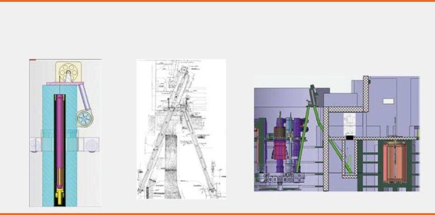
CONTENTS

    INTRODUCTION........................................................................................................................................................ 10

    EXPERIENCE FEEDBACK OF FAST REACTORS IN FRANCE AND WORLDWIDE ............................................ 13
    2.1.       Results of the operation of fast reactors worldwide ........................................................................................................... 13
    2.2.       Summary of experience feedback in various fields .......................................................................................................... 13
    2.2.1.     Experience acquired and intrinsic advantages .................................................................................................................. 13
    2.2.2.     Specific difficulties or problems ......................................................................................................................................... 14

    PRIORITY IMPROVEMENT AREAS AND ASSOCIATED R&D PROGRESS ........................................................ 19
    3.1.       Reactor safety.................................................................................................................................................................... 19
    3.1.1.     Prevention of severe accidents ......................................................................................................................................... 19
    3.1.2.     Mitigation of severe accidents ........................................................................................................................................... 23
    3.1.3.     Sodium-water risk: power conversion system .................................................................................................................. 25
    3.1.4.     Sodium leak detection ....................................................................................................................................................... 28
    3.2.       Higher availability than former SFRs and reduced shutdown times .................................................................................. 28
    3.2.1.     Instrumentation and inspection, monitoring and repairability ............................................................................................ 28
    3.2.2.     Fuel subassembly handling and cleaning.......................................................................................................................... 29

    SPECIFICATIONS AND SAFETY OBJECTIVES OF ASTRID ................................................................................. 33
    4.1.       Astrid specifications ........................................................................................................................................................... 33
    4.2.       General safety objectives ................................................................................................................................................. 33
    4.3.       General safety orientations ................................................................................................................................................ 34
    4.4.       Safety orientations in the design phase ............................................................................................................................ 34
    4.5.       Integration of internal and external hazards ..................................................................................................................... 35
    4.6.       Orientations taken to ensure the safety functions ............................................................................................................ 35
    4.6.1.     “Reactivity control” function ............................................................................................................................................... 35
    4.6.2.     “Cooling control” function .................................................................................................................................................. 36
    4.6.3.     “Radiological containment control” function ...................................................................................................................... 36
    4.7.       Orientations regarding severe accidents .......................................................................................................................... 36

6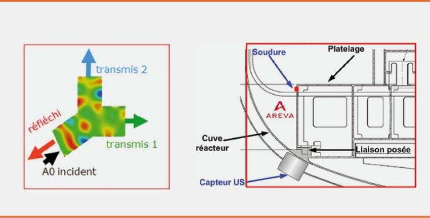
CEA | DECEMBER 2012

REQUIREMENTS TO BE COMPLIED WITH AND BASIC CHOICES FOR ASTRID ............................................... 39
5.1.      Strategic requirements ...................................................................................................................................................... 39
5.1.1.    Astrid’s power ................................................................................................................................................................... 39
5.1.2.    Astrid’s potential of transmutation demonstration ............................................................................................................ 39
5.1.3.    Astrid’s experimental potential .......................................................................................................................................... 41
5.1.4.    Resistance to proliferation ................................................................................................................................................ 41
5.2.      Safety requirements........................................................................................................................................................... 42
5.2.1     Prevention and mitigation of severe accidents ................................................................................................................. 42
5.2.2.    Decay heat removal .......................................................................................................................................................... 42
5.2.3.    Presence of a molten core catcher ................................................................................................................................... 42
5.2.4.    Inspectability of structures ................................................................................................................................................ 42
5.2.5.    Sodium risks ..................................................................................................................................................................... 42
5.3.      Security requirements ....................................................................................................................................................... 43
5.4.      Operating requirements .................................................................................................................................................................................................................................... 43

ASTRID DESIGN OPTIONS FOR MAJOR FIELDS ................................................................................................. 45
6.1.      Core and fuel .................................................................................................................................................................... 45
6.1.1.    Fuel material ..................................................................................................................................................................... 45
6.1.2.    Cladding material .............................................................................................................................................................. 45
6.1.3.    Fuel element ..................................................................................................................................................................... 45
6.1.4.    Core and subassemblies .................................................................................................................................................. 46
6.2.      Nuclear island ................................................................................................................................................................... 47
6.2.1.    Principle of “clean” primary circuit .................................................................................................................................... 47
6.2.2.    Pool type primary circuit ................................................................................................................................................... 47
6.2.3.    Presence of an intermediate circuit .................................................................................................................................. 47
6.2.4.    Internal architecture of the primary circuit ........................................................................................................................ 47
6.2.5.    Core supporting structures ................................................................................................................................................ 50
6.2.6.    Reactor block closing slab ................................................................................................................................................ 50
6.2.7.    Neutron monitoring ........................................................................................................................................................... 50
6.2.8.    Molten core catcher .......................................................................................................................................................... 50
6.2.9.    Decay heat removal .......................................................................................................................................................... 51
6.2.10.   Intermediate sodium loops ............................................................................................................................................... 51
6.3.      Power conversion system ................................................................................................................................................. 52
6.4.      Handling of fuel subassemblies ........................................................................................................................................ 52
6.4.1.    In-vessel handling .............................................................................................................................................................. 52
6.4.2.    Loading / unloading system ............................................................................................................................................... 53
6.4.3.    Ex-vessel handling ............................................................................................................................................................ 54
6.5.      In-service instrumentation and inspection (ISIR) .............................................................................................................. 54
6.5.1.    Context and approach ...................................................................................................................................................... 54
6.5.2.    In-service monitoring ........................................................................................................................................................ 55
6.5.3.    Periodical inspection ......................................................................................................................................................... 56
6.6.      Instrumentation and control ............................................................................................................................................... 57
6.6.1.    Context and approach ...................................................................................................................................................... 57
6.6.2.    Basic principles for the design of Astrid’s instrumentation and control system ................................................................ 58
6.6.3.    Architecture elements for Astrid’s instrumentation and control system ............................................................................ 58
6.6.4.    Possible technologies for the instrumentation and control system.................................................................................... 58
6.6.5.    Perspectives ..................................................................................................................................................................... 58

                                                                                                                                                                                                                                                                           7
ASSOCIATED FACILITIES FOR THE CYCLE OF ASTRID ..................................................................................... 61
     7.1.       Associated fuel cycle - Adaptation to the specific features of fast breeder reactors ......................................................... 61
     7.2.       Evolution of technologies ................................................................................................................................................... 62
     7.3.       Fuel cycle workshops ........................................................................................................................................................ 63
     7.3.1.     Core manufacturing facility (AFC) ..................................................................................................................................... 63
     7.3.2.     Used fuel processing facility (ATC) .................................................................................................................................. 64
     7.3.3.     Facility for the manufacturing of elements containing minor actinides .............................................................................. 65

    . SIMULATION AND CALCULATION CODES - QUALIFICATION ............................................................................ 67
      8.1  Modelling tools according to the schedule of the project .................................................................................................. 67
      8.2. Facilities of interest for the qualification of the core and the components of Astrid .......................................................... 68

     INDUSTRIAL ORGANISATION AND INTERNATIONAL COOPERATION OF THE ASTRID PROJECT ............... 71
     9.1        Industrial organisation of the project.................................................................................................................................. 71
     9.1.1.     Missions of the contracting authority ................................................................................................................................. 72
     9.1.2.     CEA internal organisation ................................................................................................................................................. 73
     9.2.       International cooperation .................................................................................................................................................. 73
     9.2.1.     In Europe .......................................................................................................................................................................... 73
     9.2.2.     Outside Europe ................................................................................................................................................................. 74

     SCHEDULE AND COSTS ......................................................................................................................................... 77
     10.1.      Schedule ............................................................................................................................................................................ 77
     10.2.      Cost assessment ............................................................................................................................................................... 78

      CONCLUSION .......................................................................................................................................................... 81
     11.1.      Sodium-cooled fast reactors ............................................................................................................................................. 81
     11.2.      Safety of SFRs................................................................................................................................................................... 81
     11.3.      The Astrid technological demonstrator: objectives and specifications ............................................................................. 82
     11.4.      R&D in the scope of the Astrid programme ...................................................................................................................... 83

    APPENDIX: SPECIFIC FEATURES IN THE DESIGN OF SODIUM-COOLED FAST REACTORS ........................ 87

     REFERENCES .......................................................................................................................................................... 91

8
CEA | DECEMBER 2012
91. INTRODUCTION
The sodium-cooled fast reactor (SFR) concept is one of the four Improved resistance to severe accidents and external
fast neutron concepts selected by the Generation IV International aggressions, in particular design of redundant and diversified
Forum (GIF). In addition to France, the GIF partners for the SFR decay heat removal systems, as well as aspects related to the
system are the USA, Japan, China, Russia, South Korea and risk of recriticality and to molten core containment;
Euratom.
Search for an optimised and safe power conversion system
intended to reduce or even completely remove the risk of
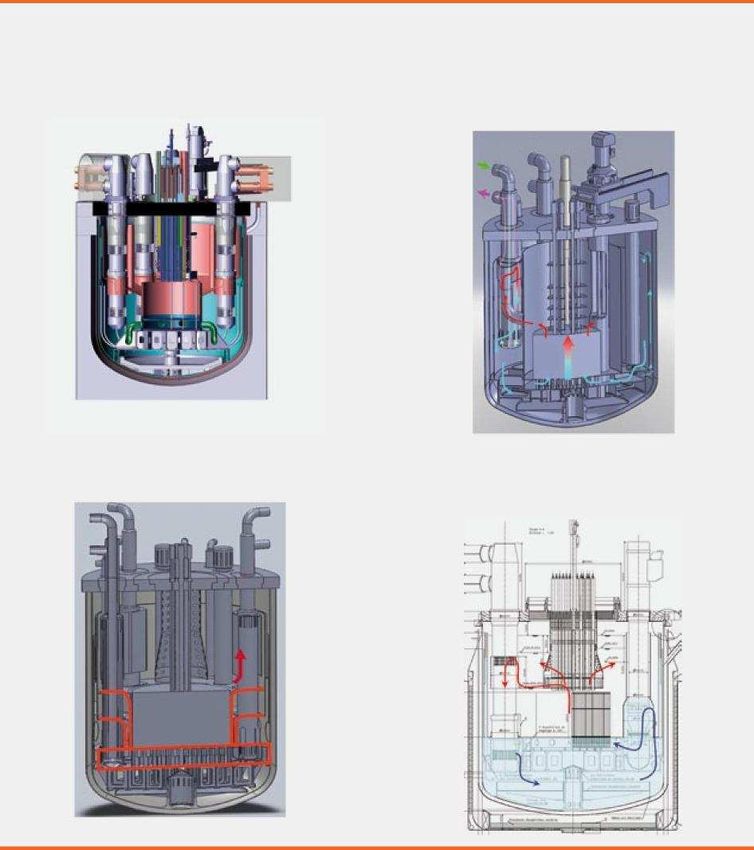
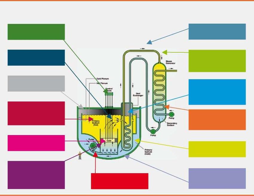
FIGURE 1: OPERATING PRINCIPLE OF interaction between sodium and water;
AN SFR
Reactor design options to make inspection and maintenance
easier and, more generally, to improve the availability, the
performance and the general economic characteristics of the
facility.
The third chapter describes these priority research fields as well
as the results obtained during the past 5 years.
The first purpose of the Astrid reactor (Astrid means “Advanced
Sodium Technological Reactor for Industrial Demonstration”) is
to demonstrate, at a sufficient scale, the abovementioned
technological progress by qualifying the innovative options
during its operation, in particular in the fields of safety and
operability. Therefore, Astrid is a technological integration
prototype which will make it possible to demonstrate the safety
and the operation of 4th generation SFRs on an industrial scale.
As we will see below, SFRs have favourable technical Astrid will also be used as a test bench for the use of advanced
characteristics and they are the sole type of reactor for which inspection and repair techniques. Its size must be sufficient to
significant industrial experience feedback is available. allow extrapolation to commercial reactors, however without
Approximately twenty prototypes or demonstrators have been being excessive, in order to limit the cost and the industrial risk.
built throughout the world and they total more than
400 reactor-years of operation, among which approximately Safety is at the heart of the Astrid project, mainly for the
100 reactor-years for the four SFRs with significant power which following reasons:
have operated over a long period at industrial level (see The acceptability of nuclear energy in the future mainly relies
Table No. 1). In France, the Phenix reactor was shut down in on the demonstrated level of safety of facilities;
2009, after more than 35 years of operation and it has become a
very significant sum of knowledge. The image of SFRs is much debated, in particular due to the
The second chapter of this Tome 3 presents a summary of the perception of their safety. The specific features of SFRs
lessons learned from the operation of SFRs at national and (positive reactivity effect in case of sodium drainage, sodium
international levels and it highlights their advantages and risks, etc.) are often highlighted, however the suitable
drawbacks. solutions are ignored and the intrinsic advantages are omitted
(absence of pressure, significant thermal inertia, etc.);
Based on this statement, in 2007, the French players (CEA,
Areva and EDF) defined an R&D programme with a system- The Fukushima accident led everyone to reconsider the safety
oriented vision whose purpose was to reinforce strong points and approaches and, through this, it has an impact on the design
reduce weak points by means of significant technological and operation of facilities.
innovations. This programme was oriented towards 4 priority
progress areas: Chapter 4 presents the specifications which the Astrid
demonstrator will have to comply with and the associated safety
Design of a high-performance core with improved safety, in objectives. Chapter 5 is dedicated to the resulting requirements
particular concerning prevention of severe accidents likely to and to the baseline choices applied to Astrid.
cause complete core meltdown;
10Chapter 6 describes, for all the components of Astrid, the design The second phase of the preliminary design, called AVP2,
options already selected and the options for which the choice still will start in 2013. It will be aimed at confirming the design in
remains open given the state of progress of the project. The main order to have a complete and consistent basic preliminary
systems defined are as follows: design by late 2014. This basic preliminary design will be
accompanied by a more thorough assessment of the cost and
the core; the schedule, and it will allow a decision to be made to
the nuclear island; continue the project.
the power conversion system; At the beginning of the preliminary design, a certain number of
design options were frozen. The options left open are subjected to
the fuel handling system; an assessment and selection process so that they can be gradually
the instrumentation in the core and the inspectability and frozen during the preliminary design.
repairability of components essential to safety; The basic design is scheduled for between 2015 and 2017; it will
the instrumentation and control system. be followed by the construction studies, the authorisation
procedures and the construction itself. The design study phase
A fuel cycle needs to be associated with a fast neutron reactor, so itself therefore runs from 2010 to 2017, according to the initial
that the whole nuclear system can be taken into consideration in schedule. At the same time, it will be necessary to carry out R&D
order to assess its overall performance. The key facilities of the actions and option selection validation actions; the results of
fuel cycle, such as the fuel manufacturing workshop and the these actions may have an impact on the contents and duration of
irradiated fuel processing workshop necessary to demonstrate the the design studies.
plutonium multi-recycling, as well as the manufacturing line for
minor actinide based elements to continue the demonstration of Chapter 9 describes this forecast schedule until the construction
the technical feasibility of long-lived nuclear waste phase and specifies the action proposed to assess the overall cost
transmutation, are specifically described in Chapter 7. The main of the project.
R&D facilities necessary for the qualification of the core and In order to make the reading of the following chapters easier, a
components of Astrid are also described. brief description of the specific features of SFRs is presented in
Pursuant to the act dated 28 June 2006, CEA became the Appendix 1.
contracting authority of the Astrid project. CEA received a
significant part of the funding for the basic design and the
associated research, via the “Investment for the future»
programme.
A specific organisation was implemented. The project was
broken down into study batches entrusted to various industrial
partners, preferentially within the scope of bilateral
collaborations with the main players of the nuclear sector or
through commercial contracts.
Chapter 8 describes this industrial organisation in detail and also
describes the international cooperation in the field of the
associated R&D.
In terms of scheduling, the work concerning the basic
preliminary design of the Astrid project started in October 2010.
It is composed of 2 phases:
The first phase of the preliminary design, called AVP1,
whose purpose is to analyse the open options, in particular
the most innovative ones, in order to select the reference
design at the end of 2012. This phase includes a preparation
phase which made it possible to structure the project,
formalise the expression of the needs and define the main
milestones and deadlines; it ended in March 2011. During the
AVP1 phase, the schedule of the project was analysed and a
preliminary cost assessment action was initiated.
11EXPERIENCE FEEDBACK OF FAST REACTORS IN FRANCE AND WORLDWIDE ............................................ 13
2.1. Results of the operation of fast reactors worldwide ........................................................................................................... 13
2.2. Summary of experience feedback in various fields .......................................................................................................... 13
2.2.1. Experience acquired and intrinsic advantages .................................................................................................................. 13
2.2.2. Specific difficulties or problems ......................................................................................................................................... 14
2.2.2.1. Material selection ............................................................................................................................................................... 14
2.2.2.2. Safety function related to control of the core reactivity...................................................................................................... 15
2.2.2.3. Fuel handling ..................................................................................................................................................................... 15
2.2.2.4. Availability and control of the risks related to the sodium technology ............................................................................... 15
2.2.2.5. In-service inspection and repairability (ISIR) .................................................................................................................... 16
2.2.2.6. Dismantling ........................................................................................................................................................................ 16
12EXPERIENCE FEEDBACK OF FAST
REACTORS IN FRANCE AND
2. WORLDWIDE
The purpose of this chapter is to summarise the experience system has totalled today 404 years of operation associated with
acquired with SFR systems in France and all over the world, all of these reactors (see Table No. 1).
analyse the incidents which occurred on this system and describe
the most mature technological options as well as the fields in It is to be noted that although Europe and the USA have
which progress is expected, in particular in terms of safety, dominated the development of this system as from the beginning,
performance, availability and cost. Asian countries now have a leading position.
2.1. RESULTS OF THE OPERATION OF FAST 2.2. SUMMARY OF EXPERIENCE FEEDBACK IN
REACTORS WORLDWIDE VARIOUS FIELDS
Since the commissioning of the first fast reactors in the 1950s,
the fleet of fast reactors in the world is comprised of 13 reactors 2.2.1. EXPERIENCE ACQUIRED AND INTRINSIC
which operated over a time period ranging between 3 and ADVANTAGES
44 years and which are shut down today, and 6 operational
reactors, among which 4 are actually in service (BOR-60, BN- Therefore, significant experience feedback exists today for the
600, FBTR, CEFR) and 2 which are being repaired (Monju and SFR system, both in terms of design, manufacturing,
Joyo). Furthermore, 2 reactors are being built (BN-800 in Russia commissioning, operation and functioning over time. In
and PFBR in India). As a result, the SFR particular in France, the expertise acquired over the 36 years of
TABLE 1: WORLD FLEET OF SFRs AND TOTAL OPERATING DURATION - SITUATION IN 2012
Thermal power Shutdown Operating duration
Reactor (Country) Start
(MW) (years)
EBR-I (USA) 1.4 1951 1963 12
BR-5/BR-10 (Russia) 8 1958 2002 44
DFR (England) 60 1959 1977 18
EBR-II (USA) 62.5 1961 1994 33
FERMI 1 (USA) 200 1963 1972 9
RAPSODIE (France) 40 1967 1983 16
SEFOR (USA) 20 1969 1972 3
BN-350 (Kazakhstan) 750 1972 1999 27
PHENIX (France) 563 1973 2009 36
PFR (England) 650 1974 1994 20
KNK-II (Germany) 58 1977 1991 14
FFTF (USA) 400 1980 1993 13
SUPERPHENIX (France) 3,000 1985 1997 12
JOYO (Japan) 50-75/100/140 1977 32
MONJU (Japan) 714 1994 15
BOR-60 (Russia) 55 1968 43
BN-600 (Russia) 1,470 1980 31
FBTR (India) 40 1985 25
CEFR (China) 65 2010 1
BN-800 (Russia) 2,100 Under construction
PFBR (India) 1,250 Under construction
Total 404
13EXPERIENCE FEEDBACK OF
FAST REACTORS IN FRANCE
AND WORLDWIDE
operation of Phenix, the experience added by the design and The control of the reactor appears to be easy, thanks to the
construction of Superphenix as well as the studies associated with absence of burnable poisons (to compensate for the excess
the EFR (European Fast Reactor) project are very rich and taken reactivity) contrary to PWRs, thanks to the absence of
into account as from the design phase of the Astrid technological poisoning effect generated by highly-neutron-absorbing
demonstrator. fission products such as xenon or samarium in PWRs, and
thanks to self-stabilising thermal feedback.
Preservation of this knowledge and reappropriation of industrial
control and R&D capabilities are also objectives of the Astrid Active or passive decay heat removal systems, based on two
programme. types of cold sources (air and water) have demonstrated their
efficiency. For the 4th generation reactors, higher
The detailed technical analysis of this experience feedback forms diversification of these systems will be aimed at in order to
the subject of specific documents. A very brief summary will further improve the safety of these facilities.
highlight the achievements and intrinsic advantages of the SFR
system: The environmental assessment is very positive and the
collective dose received by workers is very low when
The operation of SFRs has demonstrated the excellent use of compared with other types of reactors (in Phenix, over the
the uranium resource as well as the capability of these 36 years of operation, the average annual dose received by
reactors to recycle the plutonium without any limitation in the each person is 0.05 mSv, to be compared with natural
number of recycling operations (multi-recycling). Unlike the irradiation – except medical and human activities – which is
vast majority of reactors currently operated or under 2.5 mSv/year).
construction all over the world, which consume less than 1%
of natural uranium to extract the energy contained in it, SFRs However, this experience feedback also highlights difficulties or
have the capability to consume, in theory, almost the whole problems specific to SFRs.
resource via multi-recycling of the successive used fuels. In
the case of Phenix, 520 used fuel subassemblies were 2.2.2. SPECIFIC DIFFICULTIES OR PROBLEMS
reprocessed in three different facilities, which means a little 2.2.2.1. MATERIAL SELECTION
more than 26 metric tonnes of fuels. As a result, 4.4 metric
tonnes of plutonium where extracted. The breeding ratio4 was Several material selections proved to be unsuitable. For example,
confirmed and measured at 1.16. Then 3.3 metric tonnes of let us mention the crack and leakage of the ex-vessel fuel storage
this plutonium were used to manufacture new subassemblies tank55 of Superphenix in March 1987 due to the use of steel 15D3
for Phenix and these subassemblies were used in reactors, in (ferritic molybdenum steel). This steel had been selected for its
a multi-recycling strategy. high temperature performance but there was no sufficiently long
experience available as regards its use in vessels containing
The pool concept appears to be preferable to loop concept, liquid sodium.
since this pool type architecture allows in particular a very
good start of the natural circulation of the coolant and, in Similarly, steel 321 was extensively used in Phenix and PFR and,
practice, it eliminates the risk of the core being no longer after some time, it exhibited cracks due to the residual welding
immersed or the risk of loss of decay heat removal systems. stresses, in particular in the hot and thick areas. Among other
things, this phenomenon led to gradual replacement of almost all
The primary system is not pressurised but it has a very high the parts made of steel 321 in Phenix, multiple and successive
thermal inertia which provides operators with significant time repairs on the PFR steam generators and to the implementation of
to intervene in case of loss of cooling. surveillance of all parts made of steel 321 in the existing reactors.
In operation, there is a high margin with the sodium boiling This experience feedback also makes it possible to know which
temperature, typically 300°C. materials had a correct behaviour over time, and it is a
The oxide fuel is more mature when compared with the fundamental asset to design the various systems and components
limited experience feedback concerning dense fuels (carbide, of future SFRs. This experience feedback will be completed in
nitride and metal). In terms of performance, world records the years to come thanks to the dismantling of the currently shut
were achieved, in Phenix, by experimental subassemblies down SFRs throughout the world, among which Phenix and
(Boitix 9 which totalled 144 GWd/t in burn-up fraction). This Superphenix, and thanks to the sampling of irradiated materials
performance was achieved while keeping the number of clad (components, structure elements, cladding materials, fuels, etc.)
failures to a very low level. Among approximately whose analysis will considerably improve the databases. The
150,000 fuel pins irradiated in Phenix during its 36 years of Phenix reactor contains some materials which achieved records
operation, only 15 clad failures occurred (none in in terms of integrated dose and, as such, it is a real “treasure”
Superphenix), half of which occurred on experimental fuel which has to be used.
pins irradiated beyond the “standard” characteristics.
4 -– The breeding ratio is defined as the ratio of the number of produced fissile 5 – Component in which used fuels are temporarily stored in sodium to allow them
nuclei to the number of destroyed fissile nuclei per unit of time. to cool down.
14CEA | DECEMBER 2012
2.2.2.2. SAFETY FUNCTION RELATED TO CONTROL OF fuel handling incidents in FBTR and in Joyo (two years
THE CORE REACTIVITY of unavailability in the first case, probably even more in the
second case). It is to be noted that these two reactors are not
In 1989 and 1990, four emergency reactor shutdowns occurred in equipped with ultrasonic viewing systems like Phenix, which
Phenix due to the sudden drop in the core reactivity (negative could have made it possible to avoid these incidents.
reactivity trips). Even if the exact root cause of these incidents
still remains to be ascertained, the investigations performed We also have to mention the sodium leakages (one per year and
showed that fast reactors are sensitive to overall core movements. per operating reactor in average, however it is to be noted that the
Therefore, particular care must be given to this specific feature. last leakage occurred in BN-600 in May 1994), usually involving
In order to limit the risks of core compaction, options must be small quantities (approximately one kilogramme), rapidly
implemented during the design of the subassemblies, such as detected and not generating significant fires, and leakages at
bosses, called “contact pads”, to be installed on the hexagonal steam generator tubes leading to small sodium-water reactions
tubes of each subassembly so as to prevent any unwanted closing (five leakages in Phenix, approximately twelve in BN-600,
in of the tubes. approximately forty in PFR) or to a large sodium-washer
reactions (BN-350 in October 1973 and February 1975, PFR in
More generally, it will be necessary to strive for and achieve a February 1987).
natural behaviour of fast reactor cores in order to make them
more resistant to any disturbance and prevent any possibility or The analysis of the sodium-related incidents led to the conclusion
runaway of the chain reaction. that most of these incidents had no consequences on the safety of
the reactors, even if some of these incidents revealed weak points
2.2.2.3. FUEL HANDLING in the former safety demonstration. In another context, the fire
which occurred in the solar power plant of Almeria (Spain) led to
Handling of the fuel subassemblies in an SFR is significantly
a review of the basic assumptions related to the nature of sodium
different from handling in water reactors. First of all, the opacity
fires, thus improving the industrial experience feedback related to
of sodium requires to work “blind” as long as the fuel
the use of sodium.
subassemblies are inside the reactor or in the sodium storage
tank. Systems to check for movements and obstacles (ultrasonic All in all, the number of events is rather small, in particular for
“viewing” in particular) have been developed to remedy this reactors which are prototypes. For this reason, it is normal that
drawback. Then, the subassemblies need to be cleaned from the the starting phase of a reactor which is the first one of a series
sodium which may remain attached to them before they can be requires a period for adjustment and validation of the
stored in water. These operations require radiological protection technological options. The integration, during the design phase of
and they are performed using remote-controlled equipment. The future reactors, of the huge knowledge available thanks to the
experience feedback showed a gradual extension of the durations experience feedback of the operation of former projects allows us
of the core renewal campaigns, due on the one hand to equipment to expect availability rates close to those of existing Light Water
ageing (more frequent failures) and on the other hand to stricter Reactors (LWR). Therefore, for example, let us mention that the
assembly movement control procedures requiring a greater BN-600 reactor, which used the experience feedback
number of checks and hold points during the operations. accumulated in Russia thanks to the operation of prototype
Additional R&D is necessary to improve the handling and reactors and the operation of BN-350, reaches availability rates
cleaning speeds in order to preserve optimum reactor availability. comparable (and in some cases higher) to those of the Russian
water reactors. These availability rates are similar to those of the
2.2.2.4. AVAILABILITY AND CONTROL OF THE RISKS French Pressurised Water Reactors (PWR) which were started at
RELATED TO THE SODIUM TECHNOLOGY the same period (1980), such as the Tricastin 1 reactor; as a
The experience feedback shows that the incidents related to the matter of fact, BN-600 has a load factor66 of almost 75% over the
use of sodium mainly had consequences in terms of availability period between 1982 and 2008.
of the facilities (apart from the media or political context, as in The shutdown periods appear to be very significant with regard
the case of Superphenix or Monju, as this context sometimes to the number of events. Beyond the time necessary to analyse,
significantly extended the shutdown durations). The most striking investigate and repair the incident itself, the actions which
examples are given below: generate extended shutdown periods are mainly the verifications
in Superphenix, pollution by air of the primary sodium of conformity of the components or structures requested by the
(8 months of unavailability due to a faulty neoprene nuclear safety authorities. This statement proves that it is
membrane compressor) and argon leakage at an intermediate necessary to implement high-performance in-service inspection
exchanger (7 months of unavailability due to a crack on a and repairability; this remains a challenge, given the fact that
22 mm diameter tube), leakage at the storage tank (10 months sodium is opaque and reactive.
of shutdown);
oil ingress in the PFR primary system (18 months of
shutdown);
sodium leakage in Monju in 1995, leading to shutdown of the
facility until 2010;
6 – Here, the load factor, or capacity factor, is the ratio of the gross electricity
production to the gross nominal electrical power of the facility multiplied by the
operating duration considered.
15EXPERIENCE FEEDBACK OF
FAST REACTORS IN FRANCE
AND WORLDWIDE
2.2.2.5. IN-SERVICE INSPECTION AND REPAIRABILITY clads, etc.) concentrate during the service life of the reactor,
(ISIR) are equipment which generate the highest level of chemical
and radiological risks during dismantling;
Significant experience feedback has been accumulated with the
Phenix reactor in terms of maintenance and inspection, in processing of the sodium-potassium alloy (NaK) involves
particular during the programme aimed at extending the service chemical risks which require perfect control of a complex
life of Phenix. Several significant actions were carried out on the process;
reactor and its main systems. The replacement and repair of the
intermediate exchangers, primary pumps and steam generator the radiological source term is concentrated in a few
modules, which had been planned as from the design of the structures located close to the core, in particular in case of
reactor, were carried out many times and successfully. presence of some materials such as stellites which become
Significant portions of the intermediate systems were repaired, highly activated under a neutron flux (on the contrary, the
with the replacement of the base metal when it turned out that overall activity of nuclear waste produced by an SFR is lower
steel 321 was not suitable for the operating conditions of the than the activity of the waste of the other types of reactors,
hottest parts. On that occasion, an original and efficient and a significant part of the waste produced during the
procedure was developed to weld the new portions onto the dismantling operations can be disposed of through the
original pipes. A Closed Circuit TeleVision (CCTV) inspection conventional channels);
was carried out on the upper internal structures of the reactor
block, in particular the above core structure and the network of special care must be given to the tritium release limits during
fuel subassembly heads, using optical devices inserted into the the dismantling of components which were in contact with
primary system after drainage of half of the sodium (400 metric the primary sodium.
tonnes) under radiation of approximately 100 Grays per hour.
This inspection revealed that these structures were in excellent
condition after thirty years of operation. The ultrasonic test Generally speaking, the deconstruction of SFRs does not involve
performed on the conical skirt which supports the diagrid and the any technical dead end or major difficulty and it is very similar to
core inside the main vessel demonstrated that there were no the dismantling of the other types of nuclear reactors or facilities.
defects in this structure which is fundamental for the safety of the
reactor, in particular in case of earthquake. This inspection was
performed using the skirt itself as a wave guide, from the outside
of the main vessel and over a distance of more than three meters
at the heart of the primary sodium maintained at 155°C. This
operation can be qualified as “world first”.
2.2.2.6. DISMANTLING
The Superphenix reactor and several experimental SFRs are
being dismantled. The main lessons which can be learned, in
particular for the design of future SFRs, from the studies and
operations related to the dismantling of these reactors are the
following:
complete core unloading is a long operation which sometimes
requires processes or equipment items which were not
provided for in the operation phase;
complete drainage of the sodium from the reactor is also a
long operation which requires complex work; it is to be noted
that, until now, what happens to the sodium is different from
one facility to the other (direct or indirect reuse, release of
sodium salt into the river or marine environment,
incorporation into concrete);
possible presence of sodium in the form of aerosol deposits,
for instance in the penetrations of the above core structures of
reactors, needs to be taken into account during the reactor
water filling when this process is selected to provide a
biological protection during the dismantling operations;
cold traps (or similar equipment) in which sodium
compounds (oxides, hydrides, etc.) and radioactive elements
(activation products, fission products in case of leaking fuel
16You can also read