Surface Mobility Considerations for Dust Mitigation - Mike Gernhardt
←
→
Page content transcription
If your browser does not render page correctly, please read the page content below
National Aeronautics and
                                          Space Administration

Surface Mobility Considerations for
Dust Mitigation

Mike Gernhardt

                                                                 www.nasa.gov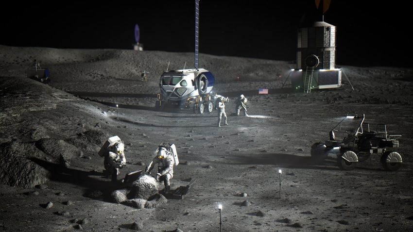
Background
• NASA has been directed to return to the lunar surface by 2024 and test systems to be
  used for a Human Mars exploration mission in the mid-2030s
• NASA has identified the need for crew exploration capabilities on the Moon and Mars that
  go beyond the crew’s ability to walk (1-2km)
• Two mobility systems have been identified in the Moon and Mars architectures to
  accomplish this requirement
    ! Unpressurised crew Mobility Platform (Lunar Terrain Vehicle)
    ! Habitable Mobility Platform

• These mobility platforms will leverage a combination of existing and emerging
  technologies for current terrestrial vehicles
• NASA desires to partner with US industry and International Partners to develop the
  required mobile platforms

                                    SENSITIVE BUT UNCLASSIFIED • NASA INTERNAL
                                                                                             2
                                           USE ONLY • DO NOT DISTRIBUTE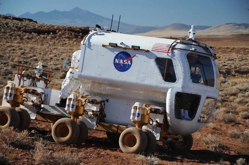
Increasing Traverse Distance Enables Discoveries

Mode of transportation:    walking       walking     walking with Mobile       LRV          LRV             LRV
                                                         Equipment
                                                      Transporter (MET)
  Approx. max. distance    ~62 m        ~450 m            ~1.4 km            ~4.7 km      ~4.4 km         ~7.5 km
      from landing site:
  BUT, number of EVAs:       1             2                 2                  3            3               3
   [This also influences
       sample number]

      An unpressurized rover will greatly extend traverse range, enabling more diverse science discoveries and increased
      operational capabilities for other tasks.
                                           SENSITIVE BUT UNCLASSIFIED • NASA INTERNAL
                                                  USE ONLY • DO NOT DISTRIBUTE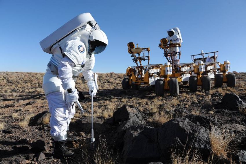
Mass of Tools and Sample Containers
     Mission             Mass          Mode of Transportaion
     Apollo 11           22.85 kg      walking                                   An unpressurized rover allows for a greater
                                                                                 amount of field equipment to be
     Apollo 12           29.17 kg      walking
                                                                                 transported on a field traverse, giving the
     Apollo 14           43.07 kg      walking w/MET                             crew a wider assortment of tools to work
                                                                                 with, and the flexibility to apply the right
     Apollo 15           50.29 kg      LRV
                                                                                 tool for the job at hand.
     Apollo 16           53.03 kg      LRV
     Apollo 17           45.69 kg      LRV

Apollo 12                               Apollo 14                                   Apollo 15-17
Hand-Held Tool Carrier              Loathed and awful MET                 Convienently Loaded with Samples and
                                      SENSITIVE BUT UNCLASSIFIED • NASA INTERNAL        Equipment
                                             USE ONLY • DO NOT DISTRIBUTE
Walking vs. Roving

• Apollo 17 landing site
• During Apollo 14 EVA 2,
  crew walked ~1.5 km
  uphill to Cone crater
  (blue circle)
• None of major science
  discoveries of Apollo 17
  mission would have
  happened without LRV

                             SENSITIVE BUT UNCLASSIFIED • NASA INTERNAL
                                    USE ONLY • DO NOT DISTRIBUTE
Four different geologic units within 10 km radial distance
of connecting ridge landing site (all impact ejecta,
sampling different parts and depths of underlying Pre-                                                              National Aeronautics and
                                                                                                                        Space Administration
Nectarian massif and/or terra material ). 3 units within 5
km radial distance, and only 2 units within 2 km radial
distance.
Relative Age

 Youngest                Copernican

                         Eratosthenian
                                                                                                                10 km radius
                                                                                                                 5 km radius
                                                                                                                 2 km radius
                         Imbrian

                         Nectarian

  Oldest                 Pre-Nectarian

 Subscripts: c, crater materials; p, plains materials; m, massif material; pl, platform massif
 material; and sc, satellitic crater (i.e., basin secondary) material [1, Imbrium basin; 2,
 Orientale basin secondaries]; and t, terra material.

                    Geology of Shackleton Crater and the south pole of the Moon
                                                          P.D. Spudis et al., 2008               SENSITIVE BUT UNCLASSIFIED • NASA INTERNAL
                                                                                                                                    www.nasa.gov
                                        Geophysical Research Letters 35: L14201                         USE ONLY • DO NOT DISTRIBUTE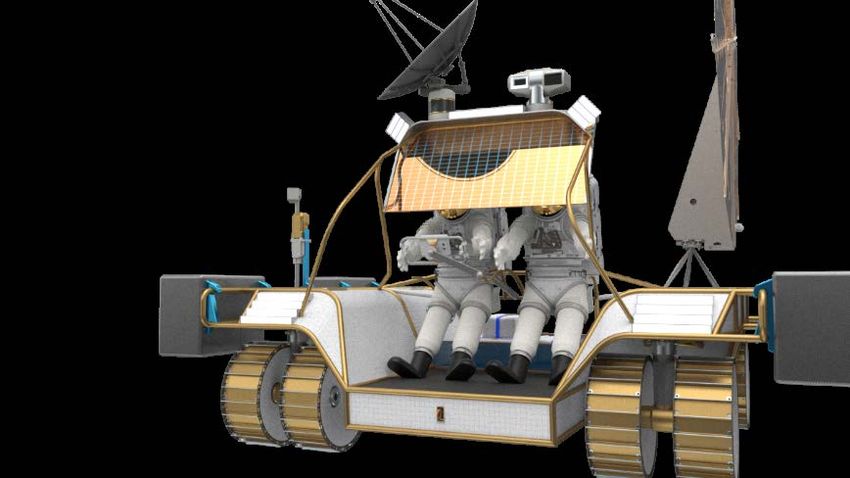
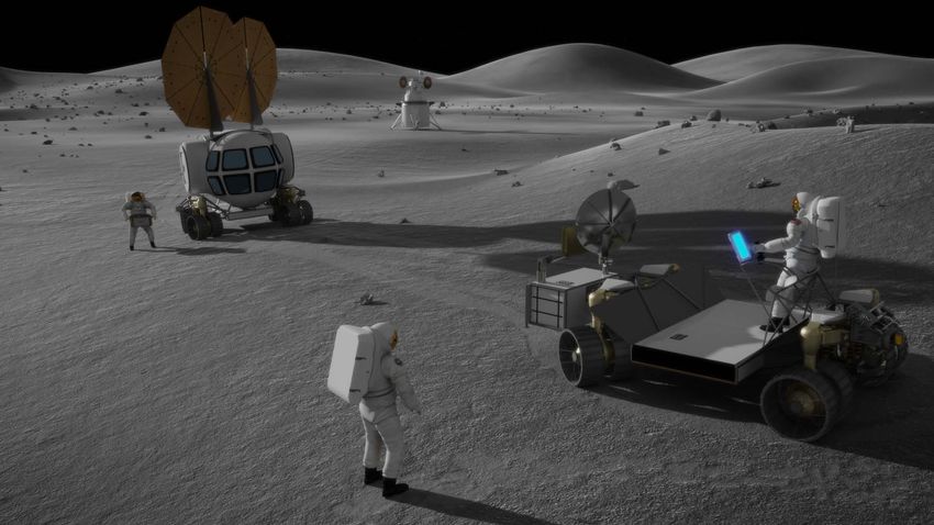
What is the LTV?
 • The Lunar Terrain Vehicle (LTV) is, in concept, very
   similar to the Lunar Rover Vehicle (LRV)
       • May require different general arrangements to address the
         unique aspects of the Lunar South Pole
 • In addition to the capabilities provided by the LRV the
   LTV will have expanded functionality such as
       • Reusable: Rechargeable & Service life (~10 yr)
       • Remote operation (HLS, Gateway, Earth, ….)
       • Ability to traverse from one landing zone to another
       • Interface with future science instruments and payloads for
         utilization or pre-deployment of assets
       • Ability to survive eclipse periods
Note: Computer-generated images of vehicles and other elements are for
illustrative purposes only and do not necessarily reflect actual designs.   7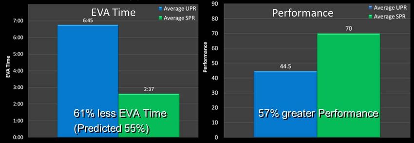
Possible Additional LTV Use Cases
• Perform science operations during uncrewed periods
    ! Outfit LTV with various science instruments including but not limited to neutron spectrometer, ground penetrating
       radar, XRF, core drills.
    ! Support resource mapping for multiple science customers including USGS (United States Geological Service)
    ! Scout future landing zones and deploy beacons
    ! Scout future EVA traverses to maximize crew surface time and facilitate detailed training
• Transport logistics and spares to point of use.
    ! Fluid logistics package including oxygen, nitrogen, water and a transfer compressor and pump package. Transfer
       to Foundational Surface habitat and Small pressurized Rover.
    ! Portable Utility pallet ( solar array and 200 watt-hrs of energy storage). Transfer to Habitat, Human landing
       system to enable night survival. Also to support in-situ resources plants operating in permanently shadowed
       regions (PSR)
    ! Transfer spares and logistics as needed in response to failures of the pressurized rover, reducing the need of the
       pressurized rover to carry a full set of spares.
• Facilitate development of infrastructure for sustained lunar presence
    ! Outfit with various earth moving packages
    ! Deploy Fission power system
    ! Deploy cables to distribute power
    ! Configure with offloading package for offloading various payloads, eliminating the need for dedicated one time
        use offloading systems                                                                                         8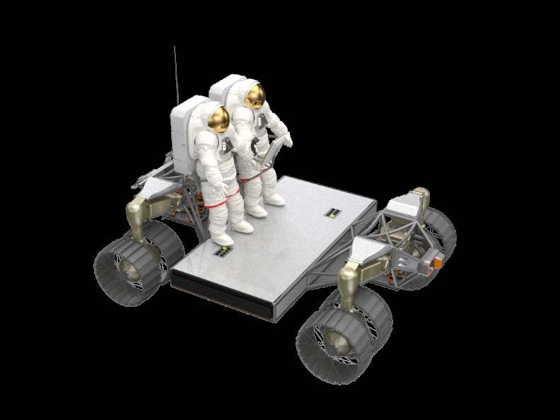
Challenges for EVA during Planetary Exploration
  • Dealing with risk and consequences of a significant Solar Particle Event (SPE)
  • Long duration missions with three 8hr EVAs per person per week
       !   Apollo suits were used no more than 3 times
       !   Individual crewmembers might perform up to 76 EVAs in a 6-month mission
       !   Suit-induced trauma currently occurs with even minimal EVA time

  • With Apollo style un-pressurized rover (UPR), exploration range is limited by EVA sortie time and 10 km
    walkback constraint
       !   Science/geology community input that optimal scientific return within this range could be accomplished within ~ 30 days of
           EVA
       !   Two UPRs could extend exploration range up to 15-20 km (crew-day limited)

  • Apollo highlighted the importance of dust control for future long duration missions
  • Increased Decompression Sickness (DCS) risk and prebreathe requirements associated with 8.2 psi 34% O2
    cabin pressure versus Apollo with 5 psi 100% O2
  • The high frequency EVA associated with the projected exploration architectures will require significant increases
    in EVA work efficiency (EVA time/prep time)

                                             SENSITIVE BUT UNCLASSIFIED • NASA INTERNAL
                                                    USE ONLY • DO NOT DISTRIBUTE
                                                                                                                                        Page 9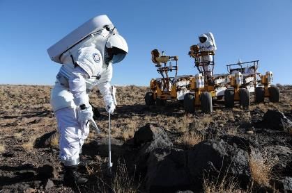
Suit Induced Trauma
“The Wall of EVA”
                   250

                                                                                                                               “The Wall”
                                                                                                                             ISS Construction
                   200

                   150
       EVA Hours

                   100
                                                          Apollo/Skylab
                                                                                             Pre-Challenger
                                                                                             Shuttle                                     Shuttle
                                 Gemini
                    50

                     0
                         196 6

                                  196 8

                                          197 0

                                                  197 2

                                                            197 4

                                                                     197 6

                                                                             197 8

                                                                                     198 0

                                                                                             198 2

                                                                                                     198 4

                                                                                                             198 6

                                                                                                                     198 8

                                                                                                                             199 0

                                                                                                                                     199 2

                                                                                                                                             199 4

                                                                                                                                                     199 6

                                                                                                                                                             199 8

                                                                                                                                                                     200 0

                                                                                                                                                                             200 2

                                                                                                                                                                                     200 4

                                                                                                                                                                                             200 6

                                                                                                                                                                                                     200 8

                                                                                                                                                                                                             201 0
                                                                                                                     Year

                                                                    SENSITIVE BUT UNCLASSIFIED • NASA INTERNAL
                                                                           USE ONLY • DO NOT DISTRIBUTE
Constellation Era: “The Mountain of EVA”
“The Mountain”
Available Lunar EVA Hours
(LAT-2 Option 2) – based on
Three 8 hour EVAs per week
using Unpressurized Rovers
à Need to extend range well
beyond 10 km
Gemini “The Wall”
Apollo/Skylab Pre-Challenger Shuttle ISS Construction
Shuttle (projected)Pressurized Rover Design Features (Slide 1 of 2)
Radiator on Roof: allows
refreezing of fusible heat sink water Suit Ports: allows suit donning and
on extended sorties vehicle egress in < 10min with
minimal gas loss.
ECLSS system with heavy
commonality with PLSS (e.g.,
swingbeds, blowers)
Ice-shielded Lock / Fusible
Heat Sink: cabin surrounded by
5.4 cm frozen water provides
SPE protection. Same ice is
used as a fusible heat sink,
rejected heat energy by melting
ice vs. evaporating water to
vacuum.
Aft Driving Station:
enables crew to drive rover
while EVA (not shown)
Suit Shelter: retractable shelter Work Package Interface:
protects EVA suits from dust, allows attachment of modular
radiation and micrometeorites. work packages e.g. winch,
cable reel, backhoe, cranePressurized Rover Design Features (Slide 2 of 2)
Exercise ergometer
(inside): allows crew to
exercise during translations
Docking Hatch: allows pressurized crew
transfer from Rover-to-Rover, Rover-to-
Habitat, and Rover- to Pressurized logistics
and/or spares depots.
Windows: provide visibility as
good, or better than, EVA suit
visibility
Cantilevered cockpit:
Mobility Chassis does not
obstruct visibility Pivoting Wheels: enables crab-
style driving for dockingPressurized Rover Design Features
16Tested Small Pressurized Rover Concept in the Field
Increases of productivity going from LTV to SPR Concept
• 1-day Traverse Distance: 31% increase
• Productivity: 57% increase
• Productivity per EVA Hour: 470 % increase
• Boots-on-Surface EVA Time: 23% increase
• Total EVA Time: 61% decrease
• Crew Fatigue: Statistically significant decrease
• Crew Discomfort: Statistically significant decreaseSummary of Health and Safety Advantages of Pressurized
Rover
• Crew typically never more than 10 mins away from safe haven
! Suit malfunctions, Solar Storms, Injury
• Radiation Protection via fusible heat sink
• Reduction of suit induced trauma because of less time in the suits
• Improved Nutrition, Hydration and
Waste Management Options- short EVAs
• Reduced Decompression Stress- exploration atmosphere, and less time in the suit
for bubbles to grow
• Pressurized Safe Haven for Treatment of Injuries or Decompression Sickness
• Exercise Countermeasures daily in the Rover (charges the batteries)
• Most effective ingress for incapacitated crew member via suit port
Note: Computer-generated images of vehicles and other elements are for
illustrative purposes only and do not necessarily reflect actual designs. 18How Will We Use the Pressurized Rover and LTV
Together?
Exploration and science
communities will do a deep
dive into traverse planning
to develop options for using
a combination of the Rover
and LTV together to exploit
the advantages of both
types of vehicles.
19
Note: All computer illustrated images of surface mobility elements in this presentation are for illustrative purposes only and do not reflect actual designs.Working with U.S. Industry Partners
• LTV development will follow a phased, iterative design, build,
test development strategy to lower risk prior to production of the
final flight unit.
• We will be working with U.S. industry to leverage the billions of
dollars that have been invested in battery technology, electric
vehicles, autonomous driving, sensor fusion and software.
20Discussion Areas for Dust Mitigation Countermeasures
Potential areas where dust may affect performance
! Radiators
! Solar Arrays
! Drive Train/Wheel Modules
! Suitport Seals
! Lights
! Sensors/Science Instruments
! Common/Standard Interfaces and Connectors that provide modularity for tools and science work packages (i.e., potential
for more frequent connect/disconnect use)
! Suits
! Windows
! Hatch/Docking Seals
• Need to take into consideration countermeasures capability in both crewed and uncrewed
scenarios
! Uncrewed
o Mechanical and/or Electromagnetic dust repulsion (for windows, radiators, solar arrays?)
o Compressed air or CO2 manifolds to clear dust from windows, radiators and solar arrays
21Discussion Areas for Dust Mitigation Countermeasures
• Need to take into consideration countermeasures capability in
both crewed and uncrewed scenarios
! Uncrewed
o Mechanical and/or Electromagnetic dust repulsion (for windows, radiators, solar arrays?)
o Compressed air or CO2 manifolds to clear dust from windows, radiators and solar arrays
o Dust tolerant drivetrain design that increases path dust has to travel to reach critical components
! Crewed
o Brushes for suits, suitport seals, and docking hatch seals
o Kickpoint to knock dust off boots before ingressing vehicles
22You can also read