T400 Concrete Mixer - Owners Manual Operating Instructions & Parts Manual - Agriquip
←
→
Page content transcription
If your browser does not render page correctly, please read the page content below
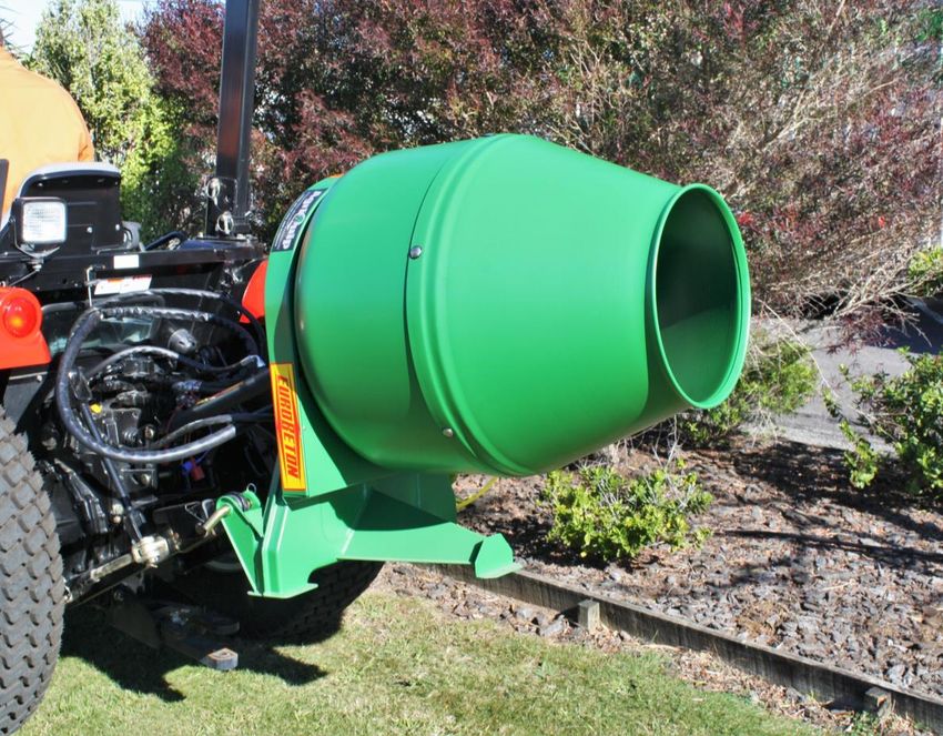
T400 Concrete Mixer

        Owners Manual
Operating Instructions & Parts Manual

         30 Hurlstone Drive, PO Box 578, NEW PLYMOUTH
               Ph: (06) 759 8402 www.agriquip.co.nz
                      support@agriquip.co.nz
                                                        November 2020

Safe Working Instructions
The machine may only be used, serviced and maintained
by persons who are aware of all the dangers. All other
persons may not operate or maintain the machine.
This operating manual must be read and observed by all
people that are to service, maintain or control the machine
so that hazards are avoided.
All safety points in this manual are indicated by this sign:
Pass on all safety precautions to other users! All warning and recommendation plates as well as
pictograms that are to be found on the machine or appliance, are of utmost importance for danger-free
operation - they are intended for your safety.
NOTE: If decals are missing, damaged or unreadable replace them
The machine may only be used for its designed use. Otherwise, all warrantees are no longer valid and
neither the manufacturer nor Agriquip are liable for any resultant injuries or damage.
All DOL-OSH guidelines are to be followed and all other general safety, medical and traffic regulations are
to be adhered to!
The manufacturer’s original parts and accessories have been designed
especially for the machine. The installation and/or use of non-original
parts and accessories can adversely effect the safe operation of the
machine. Neither the manufacturer nor Agriquip are liable for any
resultant injuries or damage caused by the use of parts and
accessories that have not been supplied by Agriquip.
Alterations and the use of auxiliary parts not approved in writing by Agriquip are not
permitted. In the event of unauthorised alterations or attachments all warrantees are null
and void.
Switch-off towing vehicle motor and allow all moving parts to come to a complete standstill
before entering the filler/unloading area and while connecting/disconnecting machine.
Perform the connecting and disconnecting operations with the mixer resting on the
ground.
All guards must be attached to the The connection bolts Secure the drive shaft
machine and maintained in good must be secured with guard with the chain to
order. All warn and damaged the key after prevent it rotating with
guards must be replaced or connection to the the drive shaft.
repaired before continuing tractor.
operations
Before engaging the power take-off,
ensure that the PTO speed is 250
rpm and rotates in the correct
direction.Safe Working Instructions (continued)
During operation do not place hands, etc. into the mixer opening.
During transport and operation do not climb onto the machine.
Always disengage the power take-off when transporting.
Before taking the machine onto public roads, ensure all reflectors
and required lights are fitted and operational.
Do not exceed the maximum overall
dimensions and weights as stated in
LTSA regulations.
Do not tow any vehicle, trailer or
implement behind the mixer.
Preparation for Use
1. Connect the mixer to the tractor using the bottom two links of
the three-point linkage.
2. Raise the three-point linkage, steadying the mixer by hand, until
the input shaft is in-line with the power take-off. (fig 1)
3. Stop raising the three-point linkage when this position has been
reached.
4. Connect the hydraulic cylinder to the third point of the tractor
three-point linkage (fig 2). Fig 1
5. Manually tilt the front (mouth) of the mixer until the mixer is in
the lowest position (emptying position). Unthread the cylinder
completely and locate it into the suitable hole of the mixer. (fig
3).
If the cylinder, completely unthreaded, is still short, it will be
necessary to connect an extension between the cylinder and
the mixer connection point. (fig 4).
6. Once the hydraulic hose is connected to the tractor tilt the mixer
using the hydraulic controls until you active the highest position Fig 2
(load position) (fig. 5).
7. When the mixer is this position, insert the drive shaft (fig 6).
It is better before you insert the drive shaft to measure the
distance between the power take-off and the input shaft. The
drive shaft should be less than 3 cm shorter in length than this
distance in order to allow sufficient play in the drive shaft during
assembly and operation. If this is not possible because of the
excessive length of the PTO shaft then follow the operations
Fig 3
described in the following section. (Length adjustment)
Fig 4 Fig 5
CAUTION: To avoid breaking or bending of the
Fig 6
forks and crosses the PTO shaft when working
must never exceed a 25° angleLength Adjustment (of Drive Shaft)
1. Hold the half-shafts close to each other in the shortest
working position and mark them. (Fig 8)
2. Shorten working inner and outer guard tubes equally. (Fig 9)
3. Shorten inner and outer sliding profiles each by the same
amount as the guard tubes. (Fig 10)
4. Round off all sharp edges and remove burrs (Fig 11).
Grease sliding profiles.
NOTE: No other changes may be made to the PTO
drive shaft and guard.
Use and Maintenance
In order to avoid side vibrations during mixer operation,
stop the side arms of the tractor moving up and down. (fig
12)
Check that the top cylinder and the mixer are in line with
the tractor (see illustration at extreme right) in order to
avoid excess strain and movement on the mixer hitch with
Fig 12
resultant wear of the pivot pin and enlargement of the
hitching fork of the mixer.
Now the machine is ready to be used, all the loading and unloading operations are
to be made exclusively with the hydraulic controls actuating the top cylinder without
lifting the bottom two three-point linkage. If these lifting bars operate when the top
cylinder is actuated it means the linkage lifting is not independent to the oil delivery
to the cylinder.
WARNING: The hydraulic systems must be independent to prevent mixer
breakage.
The mixer does not require any special maintenance; but it is a good rule to wash
the mixer bowl both inside and out after use in order to remove any concrete or
other corrosive material that could cause irreparable damage.
Lubrication
Regularly clean and grease the rim and the toothed pinion. Carefully grease
carefully the drive shaft at the points indicated at the intervals stated below.
Point Every
1 8 hrs
2 40 hrs
3 20 hrs
4 40 hrs
Mixing
For best mixing results put the ingredients into the mixer in the following sequence:
water, cement and gravel.Frame for side operation of the mixer
This device allows the mixer to be easily lifted or lowered
and loaded and unloaded to the side. This increases the
mixer’s versatility. This easy to use accessory consists of
a strong frame on which it is mounted an angle gear box
with a long and flexible drive shaft for connection to the
mixer in addition to the one connected to the PTO.
Decommissioning
Before disposing of the mixer, remove the oil from gearbox, and then dispose of the used oil and machine in
accordance with local by-laws.
NOTE: Do not just abandon the machine on a field.
Ordering Spare Parts
Quote the Machine Model, Serial Number, Year of Manufacture, Part Number and Quantity Required.
eg. Model N°: T400
Serial N°: 12345
Year: 2006
Part N°: R009.009
Quantity: 1
Item Part N° Number
1 T003.024 1
2 P004.026 2
3 C019.005 5
4 V003.194 4
5 C012.001 2
6 A005.035 1
7 S006.001-2 1+1
8 P004.003 1
9 V003.037 1
10 R004.005 1
11 R005.025 1
12 C012.019 1
13 V003.003 1
14 R004.001 1
15 C012.020 1
16 C006.016 1
17 R009.009 1
18 V003.022 3
19 R005.012 6
20 D001.002 12
21 T010.124 1
22 V003.002 3
23 R004.002 3
24 D001.002 3
25 P001.029 3
26 R009.010 1T400 Concrete Mixer
- Parts Section -
30 Hurlstone Drive, PO Box 578, NEW PLYMOUTH
Ph (06) 759 8402 www.agriquip.co.nz
support@agriquip.co.nzTable 1 Frame & Mixer Bowl Assembly – PTO Driven
Item Part No Description Qty
1 V003.014 HEXAGON HEAD SCREW 1
2 C012.001 BEARING 2
3 C012.019 BEARING 1
4 C012.020 BEARING 1
5 A005.035 DRIVE SHAFT T400 1
6 S006.001 SPRING PIN 1
7 5006.006 SPRING PIN 1
8 V003.268 HEXAGON HEAD SCREW 3
9 R005.013 FLAT WASHER 21
10 D001.005 HEXAGON NUT 15
11 V003.056 HEXAGON SCREW 3
12 R004.006 SPRING WASHER 1
13 V003.037 HEX HEAD SCREW 1
14 R005.025 FLAT WASHER 1
15 0006.016 COVER GUARD T400 1
16 R005.017 FLAT WASHER 2
17 P004.026 LIFTING PIN 2
18 C019.005 COTTER PIN 3
19 P012.026 PTO COVER 1
20 V003.171 CUP SCREW 6
21 V003.194 ROUND HEAD SCREW 10
22 R005.086 NYLON WASHER 6
23 P001.029 MIXER IRON BLADE T400 3
24 D001.006 HEXAGON NUT 2
25 P004.003 PIN FOR AGITATOR 1
26 0006.195 LOWER COVER GUARD T400 1
27 C016.012 T400 OUTER CONE SECTION 1
28 I002.001 GREASE NIPPLE 1
29 R005.080 FLAT WASHER 1
30 R009.010 T400 PINION GEAR 2005 1
31 R009.009 RING GEAR T400 2005 1
32 F006.001 INNER DRUM SECTION - COMPLETE 1
33 T003.024 MIXER FRAME T400 1Table 2 Frame & Mixer Bowl Assembly – Hydraulically Driven
Item Part No Description Qty
1 C006.016 COVER GUARD T400 1
2 0006.195 LOWER COVER GUARD T400 1
3 C016.012 T400 OUTER CONE SECTION 1
4 C019.005 COTTER PIN DM 3
5 R004.006 SPRING WASHER 1
6 F006.001 COMPLETE DRUM INNER SECTION 1
7 V003.268 HEXHEAD SCREW 3
8 R005.013 FLAT WASHER 21
9 D001.005 HEX NUT 15
10 R009.009 RING GEAR T400 2005 1
11 V003.056 HEXAGON HEAD SCREW 3
12 R005.025 FLAT WASHER 1
13 V003.037 HEX HEAD SCREW 1
14 P001.029 MIXER IRON BLADE T400 3
15 R005.080 FLAT WASHER 1
16 V003.014 HEX HEAD SCREW 1
17 1002.001 GREASE NIPPLE 1
18 P004.003 PIN FOR AGITATOR 1
19 P004.026 LOWER LINK PIN 2
20 V003.171 CUP SCREW 6
21 V003.194 ROUND HEAD SCREW 10
22 R005.086 NYLON WASHER 6
23 A005.223 COMPLETE DRIVE SHAFT 1
24 C012.001 BEARING 1
25 C012.019 BEARING 2
26 C012.020 BEARING 1
27 R009.010 T400 PINION GEAR 2005 1
28 S006.001 SPRING PIN 1
29 S006.006 SPRING PIN 1
30 T003.222 HYDRAULIC MIXER FRAME 1Table 3 Lifting Ram & Cylinder Item Part No Description Qty 1 R001.014 DOUBLE SCREW COUPLING 1 2 V004.003 VALVE WITH MALE COUPLING & CAP 1 3 R005.061 COPPER FLAT WASHER 1 4 T015.033 HOSE 1 5 T017.026 PLUG 1 6 S009.004 CYLINDER STEM 1 7 G007.011 CYLINDER STEM GUIDE 1 8 A003.011 OIL SEAL 1 9 A003.039 CYLINDER OIL SEAL 1 10 S006.010 SPRING PIN 1 11 S006.011 SPRING PIN 1 12 G007.006 CYLINDER FIXED ROD GUIDE 1 13 A003.009 OIL SEAL 1 14 A003.010 OIL SEAL 1 15 S011.002 CIRCLIP 2 16 A003.075 OIL SEAL 1 17 C003.004 CYLINDER COMPLETE SLEEVE 1 18 C013.005 DOUBLE ACTING CYLINDER 1
Table 4 Hydraulic Drive Components
Item    Part No    Description                     Qty
   1    M006.001   ORBITAL HYD MOTOR                1
   2    D001.034   HEXAGON NUT                      2
   3    R005.061   COPPER FLAT WASHER               4
   4    R001.014   DOUBLE SCREW ADAPTER             2
   5    T015.033   HOSE                             1
   6    R001.003   DOUBLE SCREW ADAPTER             1
   7    V004.003   VALVE WITH MALE ADAPTER & CAP    2
   8    T015.030   HOSE                             1
   9    R005.018   FLAT WASHER                      4
  10    V003.036   HEXHEAD SCREW                    2
Notes
_________________________________________________________________________________________
_________________________________________________________________________________________
_________________________________________________________________________________________
_________________________________________________________________________________________
_________________________________________________________________________________________
_________________________________________________________________________________________
_________________________________________________________________________________________
_________________________________________________________________________________________
_________________________________________________________________________________________
_________________________________________________________________________________________
_________________________________________________________________________________________
_________________________________________________________________________________________
_________________________________________________________________________________________
_________________________________________________________________________________________
_________________________________________________________________________________________
_________________________________________________________________________________________
_________________________________________________________________________________________
_________________________________________________________________________________________
_________________________________________________________________________________________
_________________________________________________________________________________________
_________________________________________________________________________________________
_________________________________________________________________________________________
_________________________________________________________________________________________
_________________________________________________________________________________________
_________________________________________________________________________________________
_________________________________________________________________________________________
_________________________________________________________________________________________
_________________________________________________________________________________________
_________________________________________________________________________________________
_________________________________________________________________________________________
_________________________________________________________________________________________
_________________________________________________________________________________________
_________________________________________________________________________________________
_________________________________________________________________________________________
_________________________________________________________________________________________
_________________________________________________________________________________________
_________________________________________________________________________________________
_________________________________________________________________________________________
Dealer’s Stamp
                 AGRIQUIP CONCRETE MIXER

                 Model
                                   T400

                 Man. Date / Serial N°

                 Purchase Date
Imported & Distributed by:
PO Box 578 30 Hurlstone Drive New Plymouth
+64 (06) 759 8402
www.agriquip.co.nz support@agriquip.co.nzYou can also read