Square One Shopping Centre - Long Span Glass Fin Wall - TU Delft
←
→
Page content transcription
If your browser does not render page correctly, please read the page content below
Challenging Glass 7
                                           Conference on Architectural and Structural Applications of Glass
                                            Belis, Bos & Louter (Eds.), Ghent University, September 2020.
                                                   Copyright © with the authors. All rights reserved.
                                            ISBN 978-94-6366-296-3, https://doi.org/10.7480/cgc.7.4766

Square One Shopping Centre – Long Span Glass Fin Wall
                                                 Andrew Crosby, John Kooymans
                                               Read Jones Christoffersen Ltd, Canada

           Square One Shopping Centre is owned by Oxford Properties in Toronto, Canada, and was designed by MMC
           International Architects Ltd. The shopping centre went through a recent expansion and features a large glass and steel
           rotunda for its feature entrance into the new expansion. The feature glass wall is oval in plan and is 18m tall utilizing a
           custom splicing detail to minimize the use of steel at the connections. The fin wall was analysed and tested to ensure the
           connection detail behaved as predicted. This paper will visit the design of the fin wall and review the findings of the
           physical testing performed on the connection detail.

           Keywords: Glass fin, Connection, Testing

1. Introduction
Oxford Properties were looking to design a major expansion for the Square One Shopping Centre in Mississauga,
Ontario, Canada. The architectural design team lead by Chris Brown of MMC International Architects Ltd. saw an
opportunity to anchor the expansion with a signature feature entrance. The rotunda has a large circular steel roof
supported by architecturally exposed round steel columns. We used a series of horizontal curved round steel sections
acting as wind girts to help support the glass fin wall laterally. The glass fins themselves are hung from the steel roof
structure with the glazing units toggled to the face of the glass fins resting on dead load tabs connected to the hanger.
The glass fin connections were a main focus of the design process as we were looking to simplify the connection by
using single pins at either side of the splice joint instead of the traditional connection plates. This paper will explore
the details of the rotunda construction as well as the analysis and testing of the glass fin connections and highlight
how glass connections can be reimagined.

2. Design concept
Figure 1 below shows the steel structure and glass fin locations in the design of the rotunda. There are two horizontal
girt lines within the full height glass wall to assist in supporting the glass fins against lateral wind pressures. The steel
roof trusses have outriggers to carry the hanging load of the glass wall while allowing for a glass skylight return
around the perimeter of the steel roof as shown in Figure 2.

There are several aspects to the design that help make the wall very transparent and allows for the full use of the floor
area next to the wall. The glass IGU panels are supported off a steel bar that is connected to the roof structure. The
steel bar is in turn siliconed to the glass fin for lateral load transference. This allows the glass fin to be designed for
the wind pressure loads only. The other factor in the design is the connection of the glass fins to the horizontal girts
using steel plate outriggers. This allows for the span of the glass fins to be shorter and continuous over the supports
allowing for a unique splicing connection as well as a reduced fin depth as shown in Figure 3. The final design concept
is for the glass fin to stop roughly 3m from the floor so that the bottom IGU panel is only partially supported by the
fin and allows for a “fin free” zone at the floor level all around the rotunda perimeter. Figure 4 shows a plan section
detail of the glass fin with the steel hanger bar used to carry the IGU panels. The IGU panels are fixed back to the
hanger bar with an internal toggle system and the hanger bar transfers the lateral load back to the fin through structural
silicone.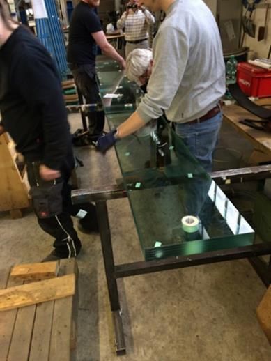
Challenging Glass 7

                           Fig. 1 Overall Rotunda geometry.

Fig. 2 Fin wall section.                                  Fig. 3 Glass fin splice detail.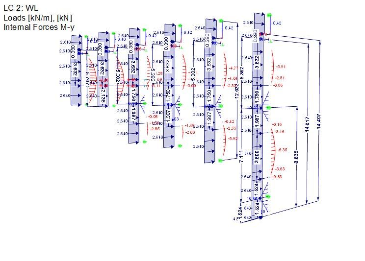
Square One shopping centre – long span glass fin wall

                                               Fig. 4 Plan section of glass fin/wall.

3. Connection/analysis
The glass fin is comprised of 6 layers of glass. This is done predominantly for redundancy and post-breakage behavior.
The fin is connected back to the steel girts via a steel outrigger plate. This plate is inserted into the glass fin allowing
for a semi-concealed connection to the main structure as shown in Figure 2. The glass splice detail uses an overlapping
connection of half the glass fin thickness with two simple pin connections within the overlapping zone to create
moment continuity and allow for shear and axial load transfer. By having the span of the glass fin shortened by the
horizontal girts and outrigger arms, the glass fin pieces can be smaller and shallower resulting in aspect ratios for each
piece that are acceptable for the tempering process. It also maintains a smaller connection force requirement at the
splice making the simple splice connection possible without using several bolts or heavier glass.

The glass fins were designed using the software program SJ Mepla with global analysis of the overall structure coming
from the software program RFEM (See Figure 5). Local models were run to check the connection design and stress
levels in the glass fins allowing for any one lite to be broken for post-breakage behavior. The splice locations were
offset from the supports in a gerber style system close to the points of zero moment to minimize the stresses at the
splices.

                                              Fig. 5 Analytical model of glass fins.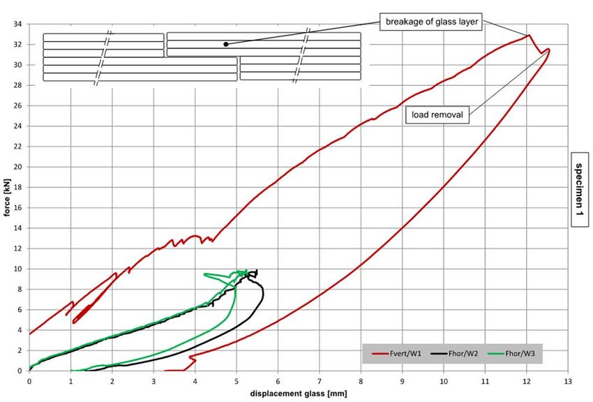
Challenging Glass 7

                                        Fig. 6 Analytical model of tested splice.

4. Connection tests
The fin splice connection was tested by the glazing contractor (Josef Gartner GmbH) as required by the contract
documents. It was tested at the Laboratory for Steel and Lightweight Metal Construction of Munich University and
Applied Sciences in Munich, Germany. Figures 7 and 8 show the test set up and procedure.

                                             Fig. 7 Glass fin splice testing.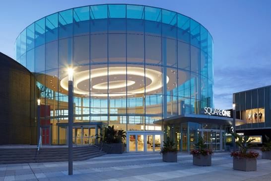
Square One shopping centre – long span glass fin wall
Fig. 8 Glass fin splice testing.
Fig. 9 Glass testing images at breakage.
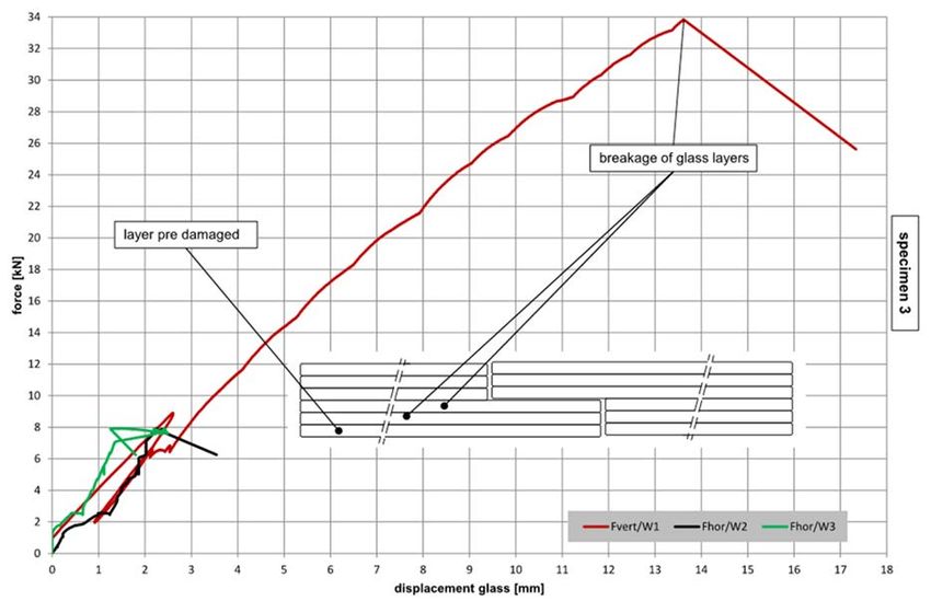
The fin was loaded vertically in a 4 point bending application to simulate the wind shear and bending forces at the
splice. The fin was also loaded axially to similuate the self weight of the glass which is transferred through the splice
and up to the top steel hanger plate. The fins were tested in unbroken and broken conditions. In the broken condition,
four specimens were tested where 1 lite of each specimen was intentionally broken prior to load application. The
unbroken tests were loaded to two times the service loading, held for 10 minutes, and then loaded to failure. The
unbroken tests had good correlation breaking at roughly five times the service loading. While the tests had good
correlation, the broken lites were always interior as seen in Figure 9 and the load at breakage was lower than expected
based on the modeled stress at the hole.
The post-breakage tests were loaded to the full service load, held for 10 minutes and then loaded to failure. The post-
breakage tests had good correlation but also broke at roughly five times the service loading. This result was not
expected since the pre-broken specimens had 2/3 the bearing area of the unbroken specimens.
The deflections observed in the testing were similar at service loading but were larger than predicted by the analytical
model at their peak loading.
Both the additional deflection and breakage of the glass were estimated to have been caused by small tolerances in
the fitted parts. Over the short distance between the bolts, small gaps can result in larger than anticipated deflections
and also allow for some rotation of the shear pins. A rotation of the shear pin can cause localized stresses on a single
lite.
While the tests failed earlier than predicted, they failed at loads that were greatly in excess of the service loads and
also showed very consistant behaviour in both the unbroken and broken tests, as seen in Figures 10, 11, 12, 13 and 14.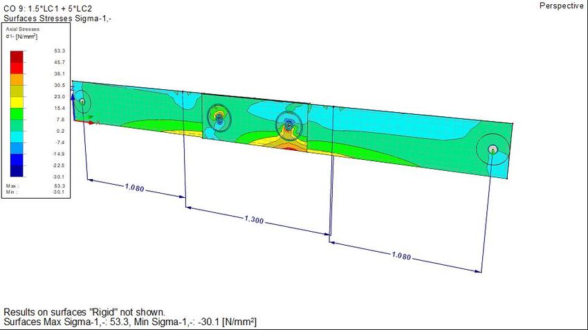
Challenging Glass 7

  Fig. 10

  Fig. 11
Square One shopping centre – long span glass fin wall

                      Fig. 12

                      Fig. 13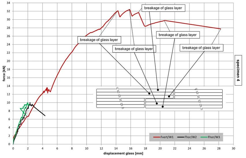
Challenging Glass 7
Fig. 14
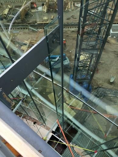
5. Construction/finished Rotunda
The construction of the rotunda went relatively smoothly. The vast column free space created a great assembly place
and main entrance for the expansion of the shopping centre. The images below speak for themselves with respect to
transparency and elegance. The custom fin wall design served its purpose of creating an iconic entrance to a very
successful shopping centre and successful project.
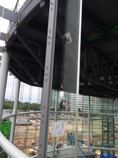
Fig. 15 Construction photo of fin splice. Fig. 16 Construction photo of hanging connection.
Fig. 17 Completed Rotunda.
Fig. 18 Competed Rotunda.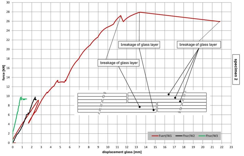
Square One shopping centre – long span glass fin wall

6. Summary
This project showed that testing custom design elements is often necessary to understand the actual behaviour of a
non-traditional assembly. It is thought that if the connection were concentric in nature, the FE results would have been
more in line with the test results. With this project, we chose a simple and elegant connection that would be easy to
assemble, but meant that there was some uncertainty in the behaviour of the connection. Small local rotations of the
shear pin appeared to have concentrated the reactive force to one lite instead of spreading it evenly over all three lites.
Testing proved that the design was safe and that we did not have any issues in a post-breakage scenario

7. Acknowledgments
Read Jones Christoffersen Ltd. would like to acknowledge the Ownership (Oxford Properties) for their forward
thinking and allowing the consulting team to design such an iconic entrance for the new expansion. We would also
like to thank MMC International Architects Ltd. for envisioning this exciting structural glass element as part of the
project. Last but not least, we would like to thank and congratulate the Contract Managers (Ellis Don Corporation)
and the Specialty Glazing Contractor (Josef Gartner GmbH) for executing the project successfully.
Challenging Glass 7

                  7   Conference on Architectural and Structural Applications of Glass
                       Belis, Bos & Louter (Eds.), Ghent University, September 2020.
                           ISBN 978-94-6366-296-3, www.challengingglass.com

PLATINUM SPONSORS

GOLD SPONSORS

SILVER SPONSORS

ORGANISING PARTNERS
You can also read