The equation of the oscillatory motion of the blade of the earth-moving machine depending on the properties of the ground and the parameters of ...
←
→
Page content transcription
If your browser does not render page correctly, please read the page content below
E3S Web of Conferences 274, 11008 (2021)                                 https://doi.org/10.1051/e3sconf/202127411008
STCCE – 2021

      The equation of the oscillatory motion of the
      blade of the earth-moving machine depending
      on the properties of the ground and the
      parameters of the blade
      Minsur Zemdikhanov1* [0000-001-5207-2346], Rustem Sakhapov1 [0000-0001-9665-1251], and Ramil
      Gainutdinov1
      1   Kazan State University of Architecture and Engineering, 420043, Zelenaya st., Kazan, Russia

                     Abstract. The influence of the design parameters and technological properties of the
                     ground on the nature of the oscillatory movement of the blade of the working body of
                     the earth-moving machine is investigated.
                     The purpose of the study is to identify the force factors of the interaction of the
                     oscillatory working body of the earth -moving machine with the ground and determine
                     its optimal parameters.
                     The equation of the oscillatory motion of the blade of the working body of the earth-
                     moving machine depending on its design parameters and technological properties of the
                     ground is obtained.
                     The results can be used in the development and determination of the optimal design
                     parameters of the working bodies of earth-moving machines.
                     Keywords: working body, oscillatory motion, knife, ground moving.

      1 Introduction
      You can increase the productivity of earth-moving machines by increasing the engine
      power and traction force. Another direction of increasing the productivity of these types of
      machines is to improve the scheme and design of their working bodies. This will allow,
      without increasing the power and traction of these types of machines, to increase its
      productivity by reducing the resistance of the ground to the working body of the earth-
      moving machine [1-4].
          When carrying out earth-moving operations in order to reduce the resistance of the
      ground to the working bodies of machines, other methods can also be used. For example,
      based on the use of vibrations or vibrations of the working body of machines (active
      working bodies), as well as a shock or explosion [5].
          Vibration organs include those working bodies on which vibration sources are installed,
      which inform the working body of vibrations of a certain frequency and in a certain
      direction. The resulting pulse load destroys the ground, thereby reducing the resistance of
      the working body, and therefore the machine [6, 7].

      *
          Corresponding author: mr.minsur@mail.ru

© The Authors, published by EDP Sciences. This is an open access article distributed under the terms of the Creative Commons
Attribution License 4.0 (http://creativecommons.org/licenses/by/4.0/).
E3S Web of Conferences 274, 11008 (2021) https://doi.org/10.1051/e3sconf/202127411008
STCCE – 2021
In earth-moving machines with blade and dump working bodies, vibration is usually
transmitted to the dump or blade of the working body of the machine.
The disadvantage of vibrating working bodies of earth-moving machines is the
complexity of the design, and sometimes a higher total energy consumption [8].
In this regard, the working bodies of machines are relevant, in which the oscillatory
movement of the blade or cutting edge occurs due to the heterogeneity of the ground
structure. Due to the heterogeneity of the ground structure, the resistance forces to the
working body of the machine will also be variable. As a result, when interacting with the
ground, there is a self-oscillating movement of the working body. Self-oscillating working
bodies, unlike working bodies with an active drive, do not require energy supply, therefore,
they have a simpler design and lower energy consumption. At the same time, they have all
the advantages of working bodies with an active drive [9-11].
The purpose of the study is to determine the influence of the technological properties of
the ground and the design parameters of the blade of the working body of the earth-moving
machine on the nature of its oscillatory movement.
2 Methods
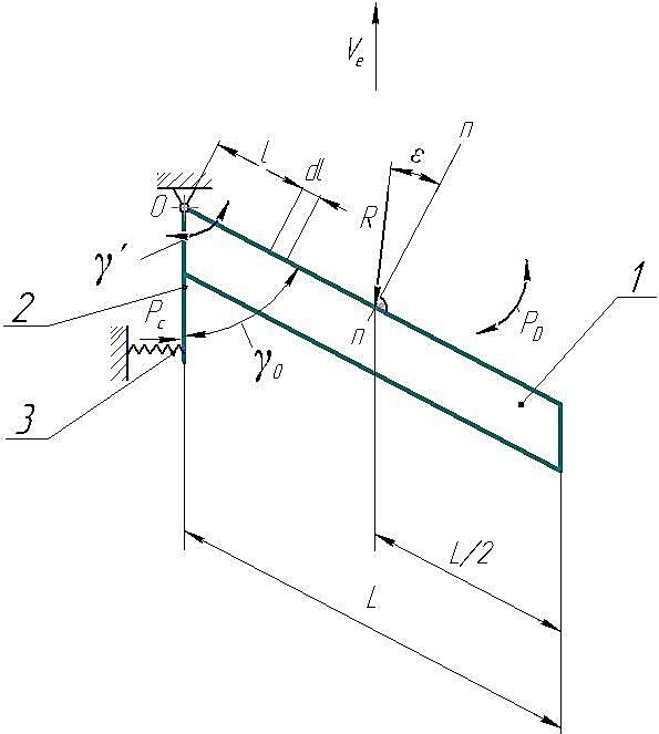
The scheme of the proposed self-oscillating working body of the earth-moving machine in
the plan is shown in Fig. 1. The angle in the plan between the direction of movement and
the line of the cutting edge of the blade when working is γ0. The blade has the ability to
rotate around the vertical axis OZ, passing through the tip of the blade (hinge A) and
perpendicular to the plane of the drawing. Also, the blade 1 is spring-loaded with a spring
3, which also in a special case can be made in the form of a torsion shaft also passing
through the OZ axis.
Fig. 1. Diagram of the forces acting on the blade of the working body.
2E3S Web of Conferences 274, 11008 (2021) https://doi.org/10.1051/e3sconf/202127411008
STCCE – 2021
Having considered the process of interaction of the blade of the working body with the
ground and determining the influence of its parameters on the parameters of self-oscillatory
motion, we can describe the equation of its oscillatory motion.
When obtaining the equation, you can consider two options for attaching a blade that
performs an oscillatory movement. The first option – the axis of rotation of the blade passes
through the leftmost tip of the cutting edge of the blade, as shown in Fig. 1. The second
option – the axis of rotation of the blade is located at some distance from the line of the
cutting edge of the blade. In this study, we will consider the first option.
In this paper, the oscillatory motion of the blade of the working body relative to the
vertical axis OZ, which also performs translational motion in the ground at a speed of Ve, is
theoretically investigated (Fig. 1).
Also, Fig. 1 shows the forces acting on the blade of the working body. The cutting edge
1 is limited from turning by the spring 3 interacting through the lever 2. In Fig. 1, the force
R, is the horizontal projection of the main vector of the ground resistance force on the
direction of the forward movement of the blade. The moment MR of the force R is balanced
by the moment MC, the force PC, acting on the blade lever from the side of the spring 2.
3 Results and discussion
The above diagram of the blade attachment requires the use of a spring 3 with high rigidity
to balance the moment MC. In this case, the self-oscillating system will have a high natural
frequency of oscillations, determined by the formula:
1 c
0 (1)
2 J
where c is the torsional rigidity of the blade turning system, H m/rad; J is the moment of
inertia of the blade with the axis and lever relative to the vertical axis OZ, kg*m^2.
With the forward movement of the working body, under the action of the constant
component of the resistance, the blade will be set at an angle γ0, at which the moments MR
and MC are mutually balanced. When the ground resistance changes, therefore, the value of
MR, the blade 1 performs an oscillatory movement at a certain angle γ relative to the
position with an angle γ0. The energy of the oscillatory motion decreases due to friction
losses. However, the inconstancy of the ground resistance force leads to the constant
occurrence of new vibrations with different amplitudes.
In this design, the frequency of natural vibrations of the working body can be adjusted
by changing the torsional rigidity of the system. For example, changing the spring stiffness
or using springs with different characteristics.
The blade is also affected by the moment MD from the dissipative forces PD of the
ground, which counteracts the oscillatory movement of the blade. Then the oscillatory
motion of the blade of the working body of the machine can be described by the following
equation:
J = M R + M C + M D (2)
where MD is the total moment of dissipative forces PD.
The moment MR of the force R is determined by the equation (Fig. 1):
L
MR = R cos , (3)
2
where L is the length of the cutting edge of the blade; ε is the angle of friction of the ground
against the cutting edge of the blade during the translational movement of the working
body.
The force R can be expressed by the formula:
3E3S Web of Conferences 274, 11008 (2021) https://doi.org/10.1051/e3sconf/202127411008
STCCE – 2021
RY
R (4)
sin( 0 )
where RY is the projection of the force R on the direction of movement of the working body;
γ0 is the angle in plan between the direction of translational movement of the working body
and the line of the cutting edge of the blade, when MR and MC are mutually balanced and
are respectively equal to MR0 and MC0.
The force of RY is written in the following form [12]:
RY k0 B0 k0 L sin 0 (5)
where k0 is the specific resistance of the ground in the direction of movement of the
working body, per unit width of the blade grip, N/m; B0 is the width of the blade grip, when
the angle between the direction of movement of the working body and the line of the
cutting edge of the blade is γ0.
Substituting RY from equation (5) into (4), we obtain:
k L sin 0
R 0 (6)
sin( 0 )
From equations (3) and (6), we obtain the following equation for determining MR0:
0 k L2 cos sin 0
MR 0 (7)
2 sin( 0 )
Given that when the angle between the direction of movement of the working body and the
line of the cutting edge of the blade is γ0, then MR0 = - MC0, we write:
0 k0 L2 cos sin 0
MC . (8)
2 sin( 0 )
When the blade moves forward, it performs an self-oscillatory movement, deviating from
the angle γ0 by a certain angle γ, then the moments MR and MC are determined by the
equations:
k L2 cos sin( 0 )
MR 0 (9)
2 sin( 0 )
k0 L2 cos sin 0 (10)
MC c
2 sin( 0 )
The energy loss of the oscillatory movement of the blade of the working body in the ground
is determined, taking into account the dry, viscous and quadratic component of the friction
force. The main moment of the dissipative friction forces is a quadratic dependence on the
angular velocity and is directed against the direction of rotation of the blade [13-15]:
M D =( b1 m1 sgn + + b3 m3 2 sgn ), (11)
where b1, b2, b3 are coefficients that depend on the properties of the soil and relate to the
dry, viscous and quadratic components of the friction force, respectively; m1, m2, m3 are
coefficients determined by the design parameters of the working body; - the Kronecker
function, respectively, having the values -1, 0, 1 at 0 [16, 17].
4E3S Web of Conferences 274, 11008 (2021) https://doi.org/10.1051/e3sconf/202127411008
STCCE – 2021
We determine the coefficients m1, m2, m3 included in equation (11), which depend on
the design parameters of the working body. The main part of the ground friction force on
the working body of the machine acting on the blade, as is known, falls on its cutting edge.
A much smaller part of the ground friction force affects the upper surface of the blade [18,
19].
Next, we write the formula (11) in the form:
M D = ( M 1 sgn + M 2 + M 3 sgn ), (12)
where M1, M2, M3 are the moments of ground resistance relative to the axis of rotation of
the blade, created by the forces of dry, viscous and quadratic friction.
Next, we define the moments M1, M2, M3 in the form of integrals:
L
L2
M 1 b1 ldl b1
2
(13)
0
L L
L3
M 2 b2 vl ldl b2 l 2dl b2
3
(14)
0 0
L
L4 2
M 3 b3 vl2ldl b3 2 l 3 dl b3
4
(15)
0
where l is the distance from the axis of rotation of the blade to the segment dl on the cutting
edge of the blade; νl is the speed of the segment of the cutting edge dl during the self-
oscillating movement of the knife.
Then m1, m2, m3 are determined by the following formulas:
L2 L3 L4
m1
; m2 ; m3 . (16)
2 3 4
After the transformations, the equation of the self-oscillating motion of the blade of the
working body (2) will take the form:
k0 L2 cos sin( 0 ) sin 0 L2 L3 L4
J c b1 sgn b2 b3 2 sgn
(17)
2 sin( 0 ) sin( )
0 2 3 4
or, by entering the appropriate notation, we get:
sin( 0 ) sin 0 2
A0 Ac A2 ( A1 A3 ) sgn 0 (18)
sin( 0 ) sin( 0 )
k 0 L2 cos c b L2 b L3 b L4
where – A0 ; AC ; A1 1 ; A2 2 ; A3 3 .
2J J 2J 3J 4J
To determine the influence of the parameters of the working body on the nature of
oscillations, equation (18) is numerically solved.
To solve these equations, it is necessary to determine the parameters that depend on the
properties of the ground. The characteristics of the ground resistance were determined as a
result of processing experimentally obtained vibrograms recorded during the movement of
the working body with certain parameters in this ground.
5E3S Web of Conferences 274, 11008 (2021) https://doi.org/10.1051/e3sconf/202127411008
STCCE – 2021
The parameters of the working body and the properties of the ground affect such
characteristics of the movement of the working body as the frequency and period of
vibrations and the attenuation decrement.
The results of the calculations are shown in Figs 2 and 3 in the form of graphs.
Fig. 2 shows the calculated vibrogram of the oscillatory motion of the working body having
the parameters: B0 0,25m, 0 450 , J 0,04kg * m^2, с 45H m/grad.
Fig. 2. Vibrogram of the oscillatory movement of the working body.
Fig. 3. Graph of the dependence of the decrement of oscillations on the amplitude.
Fig. 3 shows a graph of the dependence of the decrement of vibrations of the working body
on the amplitude of vibrations. As can be seen from the figure, the greater the amplitude of
the oscillations, the greater the decrement of the oscillations. This relationship is directly
proportional.
6E3S Web of Conferences 274, 11008 (2021) https://doi.org/10.1051/e3sconf/202127411008
STCCE – 2021
4 Conclusions
The equation (18) of motion of the blade of the working body of an earth-moving machine
is obtained, depending on the technological properties of the soil and the design parameters
of the self-oscillating working body. This equation can be used to determine the optimal
parameters of the working bodies of earth-moving machines.
When determining the influence of the parameters of the working body and the ground
on the nature of oscillatory movement of the blade, equation (18) is solved numerically.
As the solution of the resulting equation shows, the parameters of the working body and
the properties of the soil affect such characteristics of the oscillatory motion as the
frequency and period of vibrations, the decay decrement. At the same time, the greater the
oscillation amplitude, the greater the attenuation decrement. This dependence is actually
directly proportional.
References
1. Crowder Clifford D. Integral rippers for hydraulic excavator bucket, United States,
E02F3/40; E02F3/96; E02F3/04; E02F3/40
2. David H. McNabb Ripper plough for soil tillage, United States Patent 172730,
AA01B3920FI
3. Purser Ernest R. Ripper tooth attachment for a backhoe, E02F3/96; E02F3/04
4. Slaughter, James B. Adjustable ripper tooth for power shovels, United States Patent
3039210, E02F3/96; E02F3/04
5. V. L. Lapshin, Elastic-visco-plastic model for simulation of vibration separation
processes, Mountain information and analytical Bulletin, 12, 285-288 (2008)
6. A method of regulating the parameters of vibration of the working bodies and the device
for its implementation : patent 2231241 of the Rus. Federation ; decl. 07.12.2001; publ.
27.09.2004. Bull. 27, 6
7. R. L. Sakhapov, R. V. Nikolaeva, M. H. Gatiyatullin, M. M. Makhmutov, Modeling the
dynamics of the chassis of construction machines, Journal of Physics: Conference Series
738, 1, 012119 (2016) DOI: 10.1088/1742-6596/738/1/012119
8. A. I. Tretyakov, Analysis of design research in the vibrating working bodies of forestry
of tillers, Voronezh scientific and technical Bulletin, 3(5), 90-101 (2013)
9. W. Batke, J. Siebeck, H. Halama, M. Ricci, F. Tintrup, Tooth cap for construction
machinery, US Patent D463460, 2002.
10. V. A. Penchuk, Regularities of soil destruction by working bodies of machines for
earthworks, Izvestiya VUZov. Construction, 1 (1999)
11. R. Sakhapov, M. Makhmutov, Influence of removable anti-skid device on the soil
density, IOP Conference Series: Materials Science and Engineering, 786, 012021 (2020)
DOI: 10.1088/1757-899X/786/1/012021
12. I. M. Panov, Physical foundations of mechanics of soils (Phoenix, Kyiv, 266, 2008)
13. L. N. Kiseleva, V. N. Kuznetsova, The basic principles of mathematical modeling of the
interaction of the working body of the digging machine with the developed soil/ Vestnik
SibADI, 2, 5-9 (2011)
14. L. N. Kiseleva, Y. A. Fedotenko, Mathematical description of the process of interaction
of the working bodies of mines, machine developed by the soil, Omsk scientific Bulletin
of Omsk, 267-270 (2010)
15. L. N. Kiseleva, The influence of parameters chips mines, machines for traction
calculation, Interuniversity collection of works of young scientists, postgraduates and
students, 7, 246-250 (2010)
7E3S Web of Conferences 274, 11008 (2021) https://doi.org/10.1051/e3sconf/202127411008
STCCE – 2021
16. R. L. Sakhapov, M. M. Makhmutov , M. M. Zemdikhanov, Experimental model of
influence of moisture and soil type on shift resistivity, Izvestiya KGASU, 1(39), 286-
292 (2017)
17. R. L. Sakhapov, M. M. Makhmutov, Options of packages of different types of soils,
Izvestiya KGASU, 2(32), 295-299 (2015)
18. D. Bruce, Earth working sweep, US Patent 20030010157, 2003.
19. Horst Konig, Maschinen im Baubetrieb (Wiesbaden:Vieweg+Teubner Verlag, 354,
2008)
8You can also read