RECOMMENDED PRACTICE Testing of rotor blade erosion protection systems - DNVGL-RP-0171
←
→
Page content transcription
If your browser does not render page correctly, please read the page content below
RECOMMENDED PRACTICE

DNVGL-RP-0171                                                         Edition February 2018

Testing of rotor blade erosion protection
systems

            The electronic pdf version of this document, available free of charge
               from http://www.dnvgl.com, is the officially binding version.

                                     DNV GL AS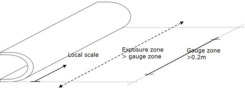
FOREWORD

DNV GL recommended practices contain sound engineering practice and guidance.

©   DNV GL AS February 2018

Any comments may be sent by e-mail to rules@dnvgl.com

This service document has been prepared based on available knowledge, technology and/or information at the time of issuance of this
document. The use of this document by others than DNV GL is at the user's sole risk. DNV GL does not accept any liability or responsibility
for loss or damages resulting from any use of this document.
CHANGES – CURRENT

                                                                           Changes - current
This is a new document.

Recommended practice — DNVGL-RP-0171. Edition February 2018       Page 3
Testing of rotor blade erosion protection systems

                                                      DNV GL AS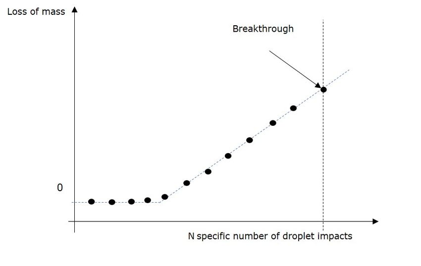
CONTENTS

                                                                                                                                       Contents
        Changes – current.................................................................................................. 3

        Section 1 General.................................................................................................. 7
                        1.1 Introduction.................................................................................... 7
                        1.2 Objective...........................................................................................7
                        1.3 Scope................................................................................................ 7
                        1.4 Application........................................................................................ 7
                        1.5 References........................................................................................ 8
                        1.6 Definitions and abbreviations........................................................... 9

        Section 2 Test procedure.....................................................................................13
                        2.1 Test procedure.............................................................................. 13

        Section 3 Rotating arm test rig........................................................................... 14
                        3.1 Outline............................................................................................ 14
                        3.2 Rotating carrier arm....................................................................... 15
                        3.3 Number of carrier arms.................................................................. 15
                        3.4 Radial position of specimen............................................................ 15
                        3.5 Distance from origin of droplet to centre of specimen in rotor
                        plane.....................................................................................................16
                        3.6 Angle of incidence.......................................................................... 16
                        3.7 Distance of test specimen to side wall........................................... 17

        Section 4 Specimens............................................................................................18
                        4.1 Geometry........................................................................................ 18
                        4.2 Material...........................................................................................18
                        4.3 Specimen preparation..................................................................... 18
                        4.4 Accelerated ageing......................................................................... 19
                        4.5 Tapes as erosion protection............................................................20

        Section 5 Test parameters...................................................................................21
                        5.1 Test condition parameters.............................................................. 21
                        5.2 Derived test parameters................................................................. 22

        Section 6 Calibration............................................................................................. 23
                        6.1 General........................................................................................... 23
                        6.2 Calibration intervals........................................................................23
                        6.3 Calibration specimens..................................................................... 23
                        6.4 Evaluation of calibration results..................................................... 24

Recommended practice — DNVGL-RP-0171. Edition February 2018                                                                  Page 4
Testing of rotor blade erosion protection systems

                                                           DNV GL AS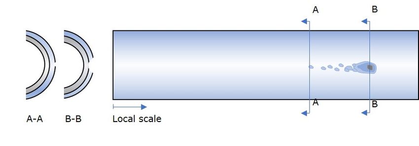
Contents
        Section 7 Inspection parameters.......................................................................... 25
                        7.1 Overview of inspection parameters................................................ 25
                        7.2 Inspection interval and time...........................................................25
                        7.3 Cleaning method............................................................................. 25
                        7.4 Inspection method..........................................................................25

        Section 8 Result parameters................................................................................. 26
                        8.1 Overview of result parameters....................................................... 26
                        8.2 Mass loss........................................................................................ 26
                        8.3 Failure modes................................................................................. 26
                        8.4 Stages of erosion progress............................................................. 26
                        8.5 End of incubation period.................................................................26
                        8.6 Breakthrough.................................................................................. 28

        Section 9 Displaying results................................................................................ 30
                        9.1 Displaying results..........................................................................30

        Section 10 Test report.......................................................................................... 32
                        10.1 Test report.................................................................................... 32

        Section 11 Summary............................................................................................36
                        11.1 Summary..................................................................................... 36

        Appendix A Specimen geometry.......................................................................... 37
                        A.1 Specimen geometry...................................................................... 37

        Appendix B Derived test parameters.................................................................... 38
                        B.1 Droplet velocity.............................................................................. 38
                        B.2 Rain intensity................................................................................. 39
                        B.3 Droplet impact velocity...................................................................39
                        B.4 Specific impact frequency...............................................................39

        Appendix C Results from round robin tests.......................................................... 43
                        C.1 Parameter overview........................................................................43
                        C.2 Reference curve for calibration specimens..................................... 47
                        C.3 Test results on coating systems..................................................... 53

        Appendix D Influences to be considered...............................................................61
                        D.1 Overview........................................................................................ 61
                        D.2 Shadowing effect............................................................................61

Recommended practice — DNVGL-RP-0171. Edition February 2018                                                              Page 5
Testing of rotor blade erosion protection systems

                                                         DNV GL AS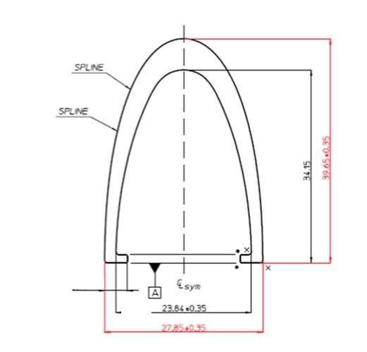
Contents
        Changes – historic................................................................................................ 63

Recommended practice — DNVGL-RP-0171. Edition February 2018                                                           Page 6
Testing of rotor blade erosion protection systems

                                                       DNV GL AS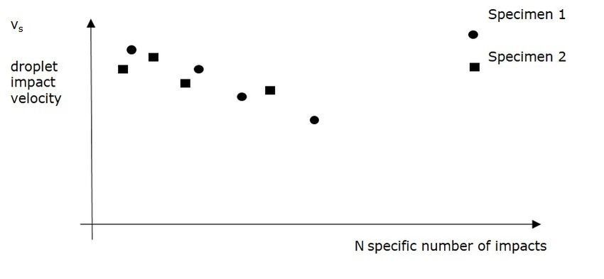
SECTION 1 GENERAL

1.1 Introduction
This recommended practice (RP) provides technical recommendations to support the execution of rain erosion
tests on rotating arm test rigs. The intention of the RP is to reach a position where results from different
rotating arm test rigs are comparable.

1.2 Objective
The objective of this recommended practice is to:
— specify a detailed test procedure for rain erosion tests (RET) performed with a rotating arm test rig to
  ensure comparable results when using different test rigs
— specify the main influencing parameters for the assessment of the rain erosion. These include:
   —   mechanical properties of the tested system (protection system + laminate)
   —   substrate preparation
   —   method of application for leading edge protection system
   —   curing conditions of the coating
   —   testing temperature
   —   accumulated number of droplet impacts to reach a pre-defined erosion stage
   —   test rig parameters, e.g.:
       — droplet size
       — droplet distribution
       — impact speed.
— specify the geometry and material of a calibration specimen
— provide guidance for defining a calibration reference band
— provide guidance for the testing of coating systems and tapes and how to document the results
— provide anonymised test results of the round robin tests.

1.3 Scope
The rain erosion performance of the test specimens is dependent on many parameters which are not
directly connected to the erosion protection system itself such as, the substrate below the protection system
(laminate and filler) and the test rig parameters. This recommended practice provides guidance as to which
parameters will influence the test results, and therefore shall be monitored and controlled during erosion
testing, to ensure comparable results when using different test rigs. As far as applicable, the parameters
are set to represent the environmental conditions that a leading edge of a rotor blade on a wind turbine is
exposed to.
In addition, guidance is provided for the selection of a calibration specimen.
The results from a round robin test on calibration specimens and on three coated specimens are anonymised
and provided in App.C. The designs of all three test rigs used for these tests were very similar.
An evaluation of the erosion test results with regards to the erosion performance, lifetime, outliers or the
required number of specimens, is not within the scope of this RP.
This RP was developed as an extension to the requirements specified in the ASTM G73-10 standard.

1.4 Application
In the following paragraphs the application of this RP compared to other publications connected to rain
erosion at DNV GL is clarified.

Recommended practice — DNVGL-RP-0171. Edition February 2018                                                Page 7
Testing of rotor blade erosion protection systems

                                                      DNV GL AS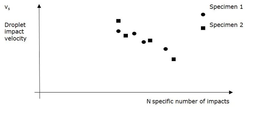
1.4.1 Testing of rotor blade erosion protection systems
This RP supports the execution of rain erosion tests on rotating arm test rigs. It specifies the boundary
conditions to ensure comparable test results on different test rigs. In addition to that, guidance for
representative test parameters is provided.
This RP does not specify requirements, such as minimum survival times, for the certification of an erosion
protection system.
The objectives of this RP are especially important for blade manufacturers who aim to improve the
performance of their erosion protection system based on different test campaigns. Also for comparisons of
test results with the erosion performance on the turbines, it is essential to have a basis of reliable and well
aligned test results.

1.4.2 Coatings for protection of fibre reinforced plastic structures with
heavy rain erosion loads
Class programme DNVGL-CP-0424 defines a test matrix to acquire a type approval for a coating system.
The class programme specifies a minimum quality level and in this way helps filter out unsuitable and
low performing materials when considering loads and ageing effects such as temperatures and climatic
influences.
The objective of the class programme and the certification of materials, is to ensure that the coating system
will be produced with a constant quality and ensures that changes in formulation and properties are correctly
documented. The class programme DNVGL-CP-0424 is not limited to erosion tests, but also covers tensile
and gloss tests at different temperatures, with and without UV exposure.
It must be emphasized that material qualifications do not consider the materials survivability under
operational loads for the turbine life.

1.4.3 Rotor blades for wind turbines
Rotor blade component certification is based on DNVGL-ST-0376 in combination with DNVGL-SE-0441.
When considering an erosion protection system within the context of a blade certification, the following
additional considerations shall be made:
— it shall be shown that the specimens are representative for the specific blade production considering the
  following items:
   —   leading edge lay-up
   —   materials
   —   substrate production method
   —   application method and quality of leading edge protection system.
— appropriate maintenance intervals and maintenance measures shall be defined.

1.5 References
Table 1-1 Normative DNV GL documents

       Document code                                                         Title

DNVGL-CP-0424                   Coatings for protection of FRP structures with heavy rain erosion loads

DNVGL-SE-0441                   Type and component certification of wind turbines

DNVGL-ST-0376                   Rotor blades for wind turbines

Recommended practice — DNVGL-RP-0171. Edition February 2018                                                 Page 8
Testing of rotor blade erosion protection systems

                                                          DNV GL AS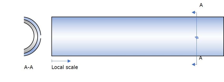
Table 1-2 Normative external documents

        Document code                                                           Title

ASTM G73-10                     Standard Test Method for Liquid Impingement Erosion Using Rotating Apparatus

ISO 2808                        Paints and varnishes - Determination of film thickness

ISO 4618:2014                   Paints and varnishes - Terms and definition

ISO 6507-1:2005                 Metallic materials - Vickers hardness test - Part 1: Test method

ISO/IEC 17025                   General requirements for the competence of testing and calibration laboratories

1.6 Definitions and abbreviations
For the purposes of this document, the terms and definitions given in ISO 4618 and the following apply.

1.6.1 Definition of verbal forms
Table 1-3 Definition of verbal forms

            Term                                                             Definition

                                verbal form used to indicate requirements strictly to be followed in order to conform with the
shall
                                document

                                verbal form used to indicate that among several possibilities one is recommended as
should                          particularly suitable, without mentioning or excluding others, or that a certain course of
                                action is preferred but not necessarily required

may                             verbal form used to indicate a course of action permissible within the limits of the document

1.6.2 Definition of terms
Table 1-4 Definition of terms

                    Term                                                                Definition

angle of incidence                              impact angle of the rain drop on the specimen surface

                                                point in time when the erosion progress breaks through the protective layer to
breakthrough
                                                the underlying substrate

droplet concentration                           number of droplets per cubic meter

end of incubation period                        exposure time until the first mass loss or damage is visually detectable

exposure zone                                   the area the rain is distributed on

failure mode                                    e.g. cracking, peeling, abrasion

gauge zone length                               the area on the specimen where the erosion performance will be evaluated

number of specific impacts                      number of impacts per projected unit area perpendicular to the impact velocity

rain intensity                                  height of raining water accumulated per unit of time

Recommended practice — DNVGL-RP-0171. Edition February 2018                                                                  Page 9
Testing of rotor blade erosion protection systems

                                                            DNV GL AS
Term Definition
specific impact frequency number of specific impacts per unit of time
stage of erosion progress reference point in time: end of incubation period or breakthrough
terminal velocity highest droplet falling velocity due to air resistance
cumulated volume of water when considering all droplets contained in a unit
water volume concentration
volume of space
1.6.3 Definitions of symbols and equations
Table 1-5 Symbols
Symbol Unit Definition
2
A [m ] area covered with rain
b [m] distance of test specimen to side wall
COV [-] coefficient of variation
d [mm] mean diameter of a droplet
g [m/s²] gravitational acceleration
I [m/s] rain intensity
k [-] constant value for power law equation
K [1/s] constant
l [m] length
L [m] length
m [-] exponent for power law equation
2
[#Impacts/m ] specific number of impacts
2 specific number of impacts N following the best fit
[#Impacts/m ]
reference line for the data points of sample j
2 specific number of impacts per unit time
[#Impacts/(s·m )]
specific impact frequency
3
P [m /s] water volumetric flow rate
3
q [#Droplets/m ] droplet concentration
r [m] radius
Ra [ μm] average surface roughness
2
[#Impacts/m ] standard deviation for specific number of impacts N
s
alternatively [m/s] (alternatively standard deviation for vs)
t [s] exposure time
v [m/s] velocity
Recommended practice — DNVGL-RP-0171. Edition February 2018 Page 10
Testing of rotor blade erosion protection systems
DNV GL ASSymbol Unit Definition
3
[m ] volume of a droplet
distance from origin of droplet to centre of specimen in
x [m]
rotor plane
2
[#Impacts/m ] mean value for specific number of impacts N
alternatively [m/s] (alternatively mean value for vs)
[°] angle of incidence
[°] half angle between rows of rain dispensers
[rad] coverage angle
[-] ratio of coverage angle and 2
[-] water volume concentration
[rad/s] angular velocity
centre point of specimen
outer point of specimen
inner point of specimen
index for number of test sample
gauge zone
rotor plane
(impact velocity of) the sample with the drops
(impact velocity of) the sample with the drops at the
centre position of specimen
reference (impact velocity of) the sample with the drops
maximum specimen (impact velocity of) droplets at the
outer position of specimen
minimum specimen (impact velocity of) droplets at the
inner position of specimen
droplet falling (velocity)
terminal droplet falling (velocity)
droplet falling (velocity) when reaching the rotor plane
where impacts with the specimen occur
(distance of) influence
Recommended practice — DNVGL-RP-0171. Edition February 2018 Page 11
Testing of rotor blade erosion protection systems
DNV GL ASSymbol Unit Definition
specimen distance
1.6.4 Abbreviations
Table 1-6 Abbreviations
Abbreviation Description
FRP fibre reinforced plastics
RP recommended practice
RET rain erosion test
Recommended practice — DNVGL-RP-0171. Edition February 2018 Page 12
Testing of rotor blade erosion protection systems
DNV GL ASSECTION 2 TEST PROCEDURE
2.1 Test procedure
Testing laboratories should comply with the requirements of ISO 17025.
The erosion damage is reproduced on specimens mounted on an arm which rotates horizontally, through
an artificial rain field. The rain impacts the surface of the test specimen and erodes the surface, which is
protected with the coating or tape, to be tested.
The degree of erosion damage caused by the droplet impacts shall be inspected and documented. This
shall be performed by visual inspection and picture documentation at defined intervals. Detailed picture
documentation enables the investigation of the initial damage at the end of the incubation period, as well as
the damage progress.
The time needed to erode the surface to a specified limit, is the measure which is used to compare the
performance of the protections systems with each other. There are two erosion stages which are commonly
used to specify the survival time of the specimens:
1) end of incubation period
2) breakthrough to the underlying substrate.
It is essential to monitor and control all parameters which influence the test result. The test apparatus,
test procedures and the substrates are not fully standardized, the parameters listed in Sec.10 shall as a
minimum, be controlled and monitored.
The relationship between accelerated erosion tests to real-life erosion is part of current research and, cannot
yet be quantified. It is currently state of art to use accelerated erosion tests with high impact speeds to
assess the performance of rain erosion protection systems.
Recommended practice — DNVGL-RP-0171. Edition February 2018 Page 13
Testing of rotor blade erosion protection systems
DNV GL ASSECTION 3 ROTATING ARM TEST RIG
3.1 Outline
An outline of the rotating arm test rig is shown in Figure 3-1. An artificial rain field may be generated over
the entire swept area of the specimen, or a part of it.
Figure 3-1 Rotating arm test rig
The test parameters relating to the rig design are shown in Table 3-1.
Table 3-1 Test rig parameters
Test parameter Unit Nominal condition
rotating carrier arm [-] aerofoil shaped with an integrated specimen
Recommended practice — DNVGL-RP-0171. Edition February 2018 Page 14
Testing of rotor blade erosion protection systems
DNV GL ASTest parameter Unit Nominal condition
number of specimen carrier arms [-] max. 3
radial position for the centre of the specimen, rc [m] min. 1.0
vertical distance from origin of droplet (needle) to
[m] min. 0.2
centre of specimen in rotor plane, x
angle of incidence, α [°] 90
distance of test specimen to side wall, b [m] to be documented
3.2 Rotating carrier arm
The aerofoil contour of the carrier arm reduces the influence of the support structure on the test result. The
influence of any uneven air flow within the test chamber, on the test results is not fully established, therefore
this influence is one of the main design drivers for the test rig. As an aerofoil contour for the carrier arm, the
specimen geometry may be used. The specimen geometry is specified in App.A.
3.3 Number of carrier arms
A maximum of three carrier arms should be used to avoid an influence of the turbulence of one specimen on
the preceding to avoid any shadowing effect (see [D.2]).
3.4 Radial position of specimen
The radial distance from the rotor centre to the centre of the test specimen shall be at least 1.0 m in order to
reduce the aerodynamic influence of the support structure (considering a constant rotational speed).
The influence of the centrifugal forces and the resulting longitudinal stresses on the test results is unknown.
Thus, a minimum radius of 1.0 m shall be specified to limit the centrifugal forces on the specimen compared
to a set impact velocity.
Recommended practice — DNVGL-RP-0171. Edition February 2018 Page 15
Testing of rotor blade erosion protection systems
DNV GL AS3.5 Distance from origin of droplet to centre of specimen in rotor
plane
Figure 3-2 Distance from origin of droplet (needle) to centre of specimen in rotor plane
The falling distance, x, from the needle to the specimen centre plane should be at least 200 mm as shown
in Figure 3-2. One reason for specifying a falling distance above 200mm is the decreasing risk of influences
from shadowing effect when the droplet falling speed is increased (see [D.2]).
3.6 Angle of incidence
The angle of incidence α is defined as shown in Figure 3-3:
Figure 3-3 Angle of incidence
Recommended practice — DNVGL-RP-0171. Edition February 2018 Page 16
Testing of rotor blade erosion protection systems
DNV GL AS3.7 Distance of test specimen to side wall
The minimum distance between the test specimen and the side wall shall be determined based on the
individual test rig and rain field. An influence of the side wall onto the test result shall be avoided.
Recommended practice — DNVGL-RP-0171. Edition February 2018 Page 17
Testing of rotor blade erosion protection systems
DNV GL ASSECTION 4 SPECIMENS
4.1 Geometry
The relevant geometry parameters for the specimens are listed in Table 4-1:
Table 4-1 Parameters related to the specimen geometry
Specimen geometry parameters Unit Nominal condition
U-shaped and integrated in the aerofoil design of the
cross-sectional shape of specimen [-]
carrier arm. Leading edge curvature shall be measured
length of exposure zone shall be larger than gauge
exposure zone [m]
zone
gauge zone length of specimen lgz [m] min. 0.2 m
4.1.1 Cross-sectional shape
A U-shaped cross section is considered most representative for rotor blade leading edges. A standard
specimen geometry is described in App.A.
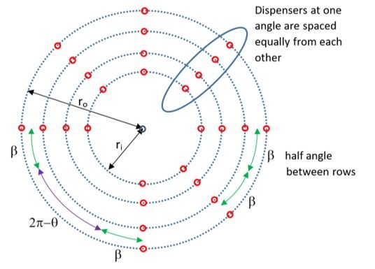
4.1.2 Exposure zone
The exposure zone is the area the rain is distributed on. It may be smaller or larger than the specimen
length. To avoid edge effects, the exposure zone shall be larger than the gauge zone. An illustration of the
exposure zone is shown in App.A.
4.1.3 Gauge zone length
The gauge zone is the area on the specimen where the erosion performance is evaluated. To avoid edge
effects, the gauge zone shall be smaller than the exposure zone. In App.A a sketch of the gauge zone is
shown.
4.2 Material
The specimens typically consist of two main components, the substrate and the protection system which shall
be tested.
If the test is referencing a particular blade or blade family, the test specimen substrate should be built with
the same materials as the leading edge in the blade production. The same is valid for the protection system,
e.g. coating or tape. Any deviation from the rotor blade production shall be documented and evaluated.
4.3 Specimen preparation
Production methods, manufacturing tolerances and materials have a large influence on the test results.
The test specimens should be built with the same production methods as the leading edges in the blade
production. Any deviation from the rotor blade production process shall be documented and the influence of
the deviations on the test results shall be evaluated.
The following parameters shall be documented:
Recommended practice — DNVGL-RP-0171. Edition February 2018 Page 18
Testing of rotor blade erosion protection systems
DNV GL ASTable 4-2 Specimen parameters
Specimen parameter Unit Nominal condition
identification number of specimen [-] to be documented
materials (fibres, resins, filler, coating
[-] as in blade production, to be documented
etc.) and material suppliers
lay-up [-] as in blade production, to be documented
surface preparation [-] as in blade production, to be documented
curing cycles, temperatures and
[-] as in blade production, to be documented
duration for substrate and coating
all layer thicknesses (filler, primer,
[μm] minimum values of blade production, to be documented
coating etc.)
coating / tape application method [-] as in blade production, to be documented
coating application quality [-] as in blade production, to be documented
4.3.1 Production method and coating/tape application
The influences of the blade production method and manufacturing tolerances on the blade leading edge area
should be considered during testing. For these considerations, all materials and layers at the leading edge
shall be considered.
For generic specimens, appropriate assumptions for the items listed above shall be made.
4.3.2 Layer thicknesses
All materials at the leading edge shall be applied with the minimum thicknesses compared to the real blade
production. The thicknesses of all layers shall be specified and measured.
The thickness of the dried leading edge protection coating shall be measured in micrometres by one of the
procedures specified in ISO 2808.
4.4 Accelerated ageing
The reference baseline testing should be performed on virgin specimens.
If climate influences are part of the test campaign, accelerated ageing of the test specimens shall be carried
out in the same manner, to the highest possible extent, as the conditions the blades are subjected to.
The following climatic parameters should be considered:
Table 4-3 Parameters for accelerated ageing
Parameter for accelerated ageing Nominal condition
extreme temperatures to be documented
UV exposure to be documented
humidity to be documented
salt spray to be documented
Recommended practice — DNVGL-RP-0171. Edition February 2018 Page 19
Testing of rotor blade erosion protection systems
DNV GL ASTo reduce the list of climatic influences for the tests, it shall be shown that the neglected climatic parameter
has no influence on the test result, or that the parameter is not relevant for the application purpose.
It must be emphasized that there is currently no approach available to reliably relate accelerated ageing of
test specimens to wind turbine site conditions.
4.5 Tapes as erosion protection
The transition area of the tape edges with the blade surface shall be investigated during testing. In addition
to that, tape edges, start and end positions, overlaps, as well as transitions between two tapes shall be
subject to erosion testing.
It shall be ensured that the differences in failure modes are appropriately covered. Tape peeling is a critical
failure mode.
Since the failure modes for coatings and tapes may be different, any comparison of test results for coatings
and tapes shall be performed very carefully.
Recommended practice — DNVGL-RP-0171. Edition February 2018 Page 20
Testing of rotor blade erosion protection systems
DNV GL ASSECTION 5 TEST PARAMETERS
5.1 Test condition parameters
5.1.1 Overview of test condition parameter
The test condition parameters that shall be specified and or monitored during test are listed in Table 5-1.
Table 5-1 Test condition parameters
Test parameter Unit Nominal condition
duration of test [min] to be specified
normal impact velocity at centre of specimen,
[m/s] to be calculated
vs,c
water temperature [°C] to be monitored
water quality [μS/cm] to be documented
to be monitored during test
test specimen temperature [°C]
or alternatively during inspection
test chamber temperature [°C] to be monitored during test
to be documented if room pressure or vacuum
test chamber pressure [Pa]
is present
mean droplet size, diameter, d [mm] ~2.0
droplet size standard deviation [mm] to be monitored prior to test
5.1.2 Duration of test
The test duration shall be defined depending on the individual incubation period and breakthrough time of the
protection system. Since this is not known at the onset of testing new protection systems, careful monitoring
of the first samples is needed to establish the test durations for subsequent test samples to establish a
baseline. The test is completed when the required level of information on the erosion progress is reached.
5.1.3 Water temperature
The influence of water temperature on erosion is not clearly understood. As a result, it is important to
measure the water temperature as close to the needle as possible for each test performed. A possible effect
of water temperature should then be evaluated during post processing of the results.
5.1.4 Water quality
The selected water quality shall be documented by measuring the conductivity or composition. Deionized
water, de-mineralized water, tap water, chloride-containing water or artificial sea water may be selected.
Recommended practice — DNVGL-RP-0171. Edition February 2018 Page 21
Testing of rotor blade erosion protection systems
DNV GL AS5.1.5 Test chamber pressure
The chamber pressure should be monitored. The erosion test should be performed at normal atmospheric
pressure.
5.1.6 Mean droplet size
The droplet size has a direct impact on the erosion damage. Therefore, test results should only be compared
for similar sized droplets.
The mean droplet size and standard deviation shall be determined and reported with a reasonable accuracy.
Furthermore, the droplet size distribution should be determined to give a better understanding of the impact
on the specimen.
Droplet sizes are dependent on many parameters and have a large influence on the erosion behaviour. The
droplet size shall be regularly measured using a laser disdrometer or appropriate methods.
5.2 Derived test parameters
5.2.1 Overview of derived test parameters
The following test parameters shall be derived from the test condition parameters specified in [5.1].
Table 5-2 Derived test parameters
Derived test parameter Unit Nominal condition
to be measured or computed from rig design
rain intensity, I [m/s]
(which needs to be defined)
max impact velocity, vs,max [m/s] to be computed
min impact velocity, vs,min [m/s] to be computed
droplet velocity when entering rotor plane,
[m/s] to be computed
vdrop,rp
specific impact frequency per unit time at
2
centre of gauge zone, Ṅc (based on mean [Impacts /(m *s)] to be computed
drop diameter, d)
The impact frequency should be selected in a way that the sample surface is able to recover after each
impact, and no water film is generated on the sample surface. It is believed that, on an operating wind
turbine, the impact frequency is not high enough for any point of the protection system to simultaneously
experience stresses resulting from separate impacts.
Further details on the calculation of these parameters are provided in App.B.
Recommended practice — DNVGL-RP-0171. Edition February 2018 Page 22
Testing of rotor blade erosion protection systems
DNV GL ASSECTION 6 CALIBRATION
6.1 General
To ensure the accuracy of the test equipment and to quantify the variation between different tests or test
rigs a standardised calibration scheme is required. Further information on calibration test results and possible
reference bands are provided in [C.2].
6.2 Calibration intervals
A calibration is mandatory when a new test rig is set up. In addition to that, calibrations shall be performed
as a minimum every second month and after any change of the test parameters.
Table 6-1 Parameters calibration intervals
Parameter Unit Nominal condition
date and time of calibration [YYYYMMDD] to be documented
Any modification of test parameters during a test campaign shall be explicitly listed.
6.3 Calibration specimens
6.3.1 Geometry
For the calibration specimens, the geometry, which is specified in App.A, may be applied.
6.3.2 Aluminium calibration specimens
For calibration specimens, the material defined in Table 6-2 and Table 6-3 may be used.
Table 6-2 Parameters for aluminium calibration material
Parameter Unit Nominal condition
specimen composition [-] EN-AW-3003, aluminium alloy
temper code [-] H112
average hardness
[HV 2] 33
ISO 6507-1:2005
3
density [kg/m ] ~2700
Young’s modulus [GPa] ~70
Table 6-3 Parameters related to manufacture and preparation of aluminium calibration specimen
Parameter Unit Nominal condition
manufacturing process [-] extruded from blocks and polished
annealing [-] none
Recommended practice — DNVGL-RP-0171. Edition February 2018 Page 23
Testing of rotor blade erosion protection systems
DNV GL ASParameter Unit Nominal condition surface roughness, Ra [μm]
SECTION 7 INSPECTION PARAMETERS
Currently, no unambiguous evaluation method of the rain erosion test results exists. The specimens are
commonly inspected visually and subsequently compared to other test results in terms of damage severity
versus test execution time.

7.1 Overview of inspection parameters
The relevant inspection parameters are listed in Table 7-1:

Table 7-1 Parameters related to inspections

Inspection parameter                                          Unit    Nominal condition

inspection interval                                       [min]       to be specified

cleaning method before inspection                             [-]     to be specified

time of inspection in relation to exposure
                                                          [min]       to be documented
time

                                                                      high resolution pictures including a scale to
picture at every inspection                                   [-]
                                                                      be documented

7.2 Inspection interval and time
Before the erosion test is started, an initial visual inspection of the test specimens shall be performed and
documented with pictures. As additional information, the specimen mass may be recorded.
The inspection interval is individually determined. It is recommended to adjust the inspection intervals and
the test time to cover both stages of erosion progress, the end of the incubation period and breakthrough,
with sufficient accuracy.
The time of inspection in relation to the execution time shall be recorded for every inspection. The inspection
interval has an influence on the accuracy of the test result. For calibration purposes, the inspection interval
should therefore be kept constant for each run.
Loss of gloss is not used to evaluate the performance of the erosion protection system.

7.3 Cleaning method
The cleaning method, which is used before each inspection, shall be specified.
The cleaning is mainly used for drying the specimens to avoid an influence of the water on the result of the
visual inspection or mass measurement.

7.4 Inspection method
The test specimens shall be inspected visually. The results shall be documented with high resolution pictures,
including a reference scale, for every inspection. It shall be ensured that the quality of the pictures is good
enough to derive the end of the incubation period. More elaborate inspection methods using microscopes
may be applied.
Each location on the specimen shall be correlated with an impact speed. Depending on the rig configuration,
the impact frequency might change along the length of the sample.

Recommended practice — DNVGL-RP-0171. Edition February 2018                                                    Page 25
Testing of rotor blade erosion protection systems

                                                      DNV GL AS
SECTION 8 RESULT PARAMETERS
8.1 Overview of result parameters
The relevant result parameters are listed in Table 8-1:
Table 8-1 Result parameters
Result parameter Unit Nominal condition
mass loss [g] optional
failure modes [-] optional
reference point in time: end of incubation period and
stages of erosion progress [-]
breakthrough
document time of initial surface damage for each
end of incubation period [min]
location
breakthrough [min] document time of breakthrough for each location
8.2 Mass loss
The mass loss of the calibration specimens may be measured and monitored at the inspections. The mass
loss is used to monitor the erosion damage development on the complete specimen and independent of the
eroded layers.
8.3 Failure modes
The different failure modes of the leading edge protection systems, such as cracking, peeling, and abrasion,
may be documented as additional information. This information might be important to evaluate the reasons
for varying performance levels of the leading edge protection systems. It shall be ensured that the failure
modes, which are triggered during testing, are comparable to the failure modes seen on the turbines.
8.4 Stages of erosion progress
The stages of erosion progress are reference points in time which may be used to assess the remaining
protective efficacy of the erosion protection system and to compare the performance of different systems
with each other. In context of this recommended practice, the end of the incubation period and breakthrough
are specified as they are the most commonly used stages of erosion progress.
8.5 End of incubation period
The incubation period is defined as the exposure time until the first damage is visually detectable on the
outer surface of the test specimen. The incubation period depends on the impact speed and thus, for rotating
arm test rigs, on the position on the specimen.
An illustration of an initial surface damage for a protected specimen is shown in Figure 8-1:
Recommended practice — DNVGL-RP-0171. Edition February 2018 Page 26
Testing of rotor blade erosion protection systems
DNV GL ASFigure 8-1 Illustration of initial surface damage at the end of the incubation period
The first visual surface damage can be caused by different failure modes (e.g. cracking, peeling, abrasion).
In some cases, the initial damage is not located on the outer surface, but in the underlying layers, and is
thus not visible until a piece of the material is suddenly removed. Methods to measure damage below an
undamaged surface are not yet common in rain erosion testing.
Loss of gloss is not considered to be damage.
For determining the end of the incubation period on rotating arm test rigs, as described in [3.1], measuring
mass loss is not an appropriate parameter, since it is providing information about the status of the complete
specimen, independent of the rotational speed and the affected layer.
Thus, for visualization purposes only, Figure 8-2 uses mass loss to describe the meaning of incubation period.
Figure 8-2 Visualization of the incubation period based on mass loss for one specific section, e.g.
section A-A of Figure 8-1
Recommended practice — DNVGL-RP-0171. Edition February 2018 Page 27
Testing of rotor blade erosion protection systems
DNV GL ASGenerally, it shall be clearly specified how the end of the incubation period is defined, how it is detected and
which approximate resolution the detection method has. Especially for tapes, a detailed definition of the end
of the incubation period and the differentiation to breakthrough (see [8.6]) is important.
8.6 Breakthrough
Breakthrough is defined as the point in time when the erosion breaks through the protective layer to the
underlying substrate. It shall be clearly defined which layers belong to the substrate (e.g. laminate, topcoat
etc.). The time of breakthrough depends on the impact velocity and thus, for rotating arm test rigs (as
described in [3.1]), it also depends on the location on the specimen.
The end of the incubation period and breakthrough may be equal in some cases. This might apply when the
initial damage is caused on the underlying layers and develops without visible damage on the surface, until a
piece of protection layer is suddenly removed.
An illustration of the breakthrough erosion stage is shown in Figure 8-3.
Figure 8-3 Illustration of breakthrough erosion stage in B-B compared to the initial surface
damage at the end of the incubation period in A-A
As described in [8.5], loss of mass is not an appropriate parameter to define erosion progress stages for the
chosen test rig configuration (see [3.1]). However, for visualization purposes only, Figure 8-4 uses mass loss
to provide further information on the breakthrough erosion stage.
Recommended practice — DNVGL-RP-0171. Edition February 2018 Page 28
Testing of rotor blade erosion protection systems
DNV GL ASFigure 8-4 Visualization of breakthrough based on mass loss for homogeneous specimen material
Looking at the theoretical graph of mass loss vs number of droplet impacts, the point of breakthrough will
be shown as a change of slope, since the underlying substrate has different erosion properties than the
protective layer.
Breakthrough times should be determined conservatively, by using the time-step before breakthrough is
detected on the pictures.
Recommended practice — DNVGL-RP-0171. Edition February 2018 Page 29
Testing of rotor blade erosion protection systems
DNV GL ASSECTION 9 DISPLAYING RESULTS
9.1 Displaying results
An incubation curve may be expressed in terms of the recorded ends of incubation periods at different impact
velocities and specific numbers of impacts, see Figure 9-1.
Figure 9-1 Result data for end incubation period shown as droplet impact velocity vs specific
number of droplet impacts (axes on a logarithmic scale)
The vs versus N diagrams, as shown in Figure 9-1 may be developed assuming that the data cloud is
described by a power law:
As often used for traditional fatigue S/N curves, the equation may be specified with N as the dependent
parameter:
As a next step, the data is transformed into a log-log scale and the parameters k and m are determined
using a least square fit:
If the end of the incubation period is plotted for droplet impact velocity versus specific number of impacts,
the diagram resembles traditional fatigue S/N curves where the induced stresses are displayed versus the
number of cycles.
Since, for the test rig configuration specified in [3.1], the impact speed increases with the radial position
on the specimen, one test specimen provides information for several impact velocities. However, the
establishment of an incubation curve requires visual detection of initial damages at the individual specimen
cross-sections.
Recommended practice — DNVGL-RP-0171. Edition February 2018 Page 30
Testing of rotor blade erosion protection systems
DNV GL ASBreakthrough data may be expressed in the same way, as shown in Figure 9-2:
Figure 9-2 Breakthrough data shown as droplet impact velocity versus specific number of droplet
impacts (axes on a logarithmic scale)
Recommended practice — DNVGL-RP-0171. Edition February 2018 Page 31
Testing of rotor blade erosion protection systems
DNV GL ASSECTION 10 TEST REPORT
10.1 Test report
The test report should comply with ASTM G73-10. Further a test parameter overview, as shown in Table
10-1, shall be summarized by collecting the parameters specified in Table 3-1 to Table 8-1 in this document.
Table 10-1 Summary of parameters to be documented in the test report.
Deviations from
Test parameter Unit Nominal condition
nominal condition
aerofoil shaped with an
specimen carrier arm [-]
integrated specimen
number of specimen
[-] max. 3
carrier arms
radius position of centre
Test rig
of specimen attachment, [m] min. 1.0
rc
distance from origin
of droplet to centre of
[m] min. 0.2
specimen in rotor plane,
x
angle of incidence [°] 90
U-shaped and integrated
in the aerofoil design of
cross-sectional shape of
[-] the carrier arm. Leading
specimen
Specimen geometry
edge curvature to be
measured.
gauge zone length of
specimen, lgz (zone
[m] min. 0.2
where erosion is
evaluated)
exposure zone [m] larger than gauge zone
Recommended practice — DNVGL-RP-0171. Edition February 2018 Page 32
Testing of rotor blade erosion protection systems
DNV GL ASDeviations from
Test parameter Unit Nominal condition
nominal condition
identification number of
[-] to be documented
specimen
materials (fibres, resins, as in blade production
filler, coating etc.) and [-]
material suppliers to be documented
as in blade production
layup [-]
to be documented
Specimen preparation
as in blade production
surface preparation [-]
to be documented
curing cycles,
temperatures and as in blade production
[-]
duration for base to be documented
laminate and coating
all layer thicknesses minimum values from
(filler, primer, coating [μm] blade production
etc.) to be documented
coating/tape application as in blade production
[-]
method to be documented
as in blade production
coating application quality [-]
to be documented
extreme temperatures [-] to be documented
UV exposure [-] to be documented
Accelerated ageing
humidity [-] to be documented
salt spray [-] to be documented
duration of test [min] to be specified
normal impact velocity at
[m/s] to be calculated
centre of specimen, vs,c
Test conditions
water temperature [°C] to be monitored
water quality [μS/cm] to be documented
test specimen to be monitored during
[°C]
temperature test
test chamber to be monitored during
[°C]
temperature test
Recommended practice — DNVGL-RP-0171. Edition February 2018 Page 33
Testing of rotor blade erosion protection systems
DNV GL ASDeviations from
Test parameter Unit Nominal condition
nominal condition
to be monitored during
test chamber pressure [Pa]
test
mean droplet size,
[mm] ~2.0
diameter
droplet size standard to be monitored prior to
[mm]
deviation test
to be measured or
rain intensity in exposure
computed from rig design
zone (exposure zone [m/s]
(which needs to be
needs to be defined)
defined)
Derived test parameters
max impact velocity,
[m/s] to be computed
vs,max
min impact velocity, vs,min [m/s] to be computed
droplet velocity when
entering rotor plane, [m/s] to be computed
vdrop,rp
specific impact frequency
per unit time in exposure [Impacts /
2 to be estimated
zone, Ṅc (based on mean (m *s)]
drop diameter)
Calibration
date and time of
[YYYYMMDD] to be documented
calibration
specimen composition [-] EN-AW-3003
temper code [-] H112
Calibration material
average hardness,
[HV 2] 33
ISO 6507-1:2005
3
density [kg/m ] ~2700
Young’s modulus [GPa] ~70
Recommended practice — DNVGL-RP-0171. Edition February 2018 Page 34
Testing of rotor blade erosion protection systems
DNV GL ASDeviations from
Test parameter Unit Nominal condition
nominal condition
extruded from blocks and
manufacturing process [-]
polished
annealing [-] none
Calibration process
surface roughness, Ra [µm]SECTION 11 SUMMARY
11.1 Summary
In this recommended practice, the influencing parameters for erosion tests on rotating arm test rigs were
specified and in some cases nominal values were recommended. Furthermore, an aluminium calibration
specimen is introduced. The performed round robin tests show comparable erosion performances for the
three rotating arm test rigs. The round robin test results are listed in App.C.
Recommended practice — DNVGL-RP-0171. Edition February 2018 Page 36
Testing of rotor blade erosion protection systems
DNV GL ASAPPENDIX A SPECIMEN GEOMETRY
A.1 Specimen geometry
Figure A-1 Gauge length explanation
Figure A-2 Specimen cross-section based on NACA 634-021
Recommended practice — DNVGL-RP-0171. Edition February 2018 Page 37
Testing of rotor blade erosion protection systems
DNV GL ASAPPENDIX B DERIVED TEST PARAMETERS
B.1 Droplet velocity
If the initial speed of the droplet at the needle is zero, the velocity of the drop is a function of how far the
drop falls from the needle to the sample, x, and the droplet diameter, d.
Figure B-1 Illustration of specimen impact velocity and droplet falling velocity
vdrop,rp = droplet falling velocity when reaching the centre of specimen in the rotor plane
x = distance from origin of droplet (needle) to centre of specimen in the rotor plane
For droplet sizes of 0.1 mm to 3 mm, the terminal velocity of the droplet may be defined by using the
following empirical relation in ASTM G73-10:
where d is the mean droplet diameter in [mm].
If the travel distance is not high enough for the droplets to reach terminal velocity when reaching the rotor
plane (vdrop,rp = vdrop,max), the droplet velocity may be derived from the two following relations:
using x(t = 0) = 0
Recommended practice — DNVGL-RP-0171. Edition February 2018 Page 38
Testing of rotor blade erosion protection systems
DNV GL ASThe velocity as function of time is established from the equilibrium equation in terms of an object falling
freely in air. Using this equation, the velocity of the droplet when reaching the rotor plane, v(t@rp) =
vdrop,rp, may be calculated.
Alternatively, the droplet velocity may be determined experimentally by using a laser disdrometer.
B.2 Rain intensity
In line with ASTM G73-10, the rain intensity, I , may be directly derived from the water flow, P , and the area
the water is distributed over, A . Thus, the rain intensity is calculated as:
The area is dependent on how the rain field is generated. In cases where the rain is only generated directly
over the specimen gauge zone, the area may be computed as:
where:
ro =
ri =
φ =
In this case, θ is the angle coverage where the rain is generated, and φ the distribution ratio.
B.3 Droplet impact velocity
The droplet falling velocity is very small compared to the sample travelling velocity. Thus, the resulting
impact velocity is assumed to be equal to the sample speed.
For the test rig configuration specified in this document, the impact velocity distribution, vs(r), across the
gauge zone is linearly related to the radial position on the specimen carrier arm and the angular velocity:
B.4 Specific impact frequency
The number of specific impacts, in terms of number of droplet impacting on a unit area during the exposure
time, t is computed from the droplet concentration, q, and the impact speed, vs:
Thus, the specific impact frequency per unit time at the gauge zone centre is quantified as:
Recommended practice — DNVGL-RP-0171. Edition February 2018 Page 39
Testing of rotor blade erosion protection systems
DNV GL ASThe droplet concentration, q, is the number of droplets per cubic meter. It is estimated from the water
volume concentration, ψ, and the volume of a single droplet, Vdrop, which is based on the mean droplet
diameter:
The water volume concentration, ψ, may either be experimentally characterized or estimated from the rain
intensity, I, and the droplet falling velocity, vdrop,rp, when entering the rotor plane:
The leads to the following equation for the droplet concentration, q:
The specific impact frequency,Ṅc shall be reported to give an indication of the impact rate of the test setup.
The number of specific impacts N should be used for expressing results.
On some machine setups, in order to have a constant specific impact frequency along the sample's length,
the rain intensity is intentionally inhomogeneous. The evaluation of the specific impact frequency for one
example of such a rain intensity repartition is shown below.
In order to keep the specific impact frequency, Ṅ, constant along the samples being tested, one solution is to
generate the rain field through dispensers organized radially, in a spider web shape.
Recommended practice — DNVGL-RP-0171. Edition February 2018 Page 40
Testing of rotor blade erosion protection systems
DNV GL ASFigure B-2 Dispensers set following a spider web pattern
For most machines, the above drawing is not exactly accurate as dispensers would, by design, not have
exactly the same radial position from one row to the other, in order to homogenize the rain flow along the
sample.
It is also common, as shown in the drawing, to have a certain angular section without dispensers, required
for example, to fit the needs of automatic inspection equipment. The complementary angle is called the angle
of coverage θ.
With such a distribution of dispensers, if we consider an area delimited by 2 circles of arbitrary radius r and r
+ Δr, we can see that the number of dispensers do not depend on r (provided that the discreet distribution of
dispensers is approximated by an equivalent continuous distribution). We can therefore write that:
with θ being the angle of coverage in radians.
In order to keep the specific impact frequency, Ṅc constant, it has to be independent of the radius r and the
rain intensity I(r) has to be proportional to l/r:
We find the constant K through the total flow of water P which us poured over the covered area:
Recommended practice — DNVGL-RP-0171. Edition February 2018 Page 41
Testing of rotor blade erosion protection systems
DNV GL ASReplacing constant K , the rain intensity in the covered area can then be expressed as:
As shown earlier, q can be expressed through the water volume concentration and the volume of a drop:
Replacing q and vs , the specific impact frequency in the covered area, can be expressed as:
And by replacing the rain intensity I :
Deducing from this, we see that the specific impact frequency is independent of the radial position, hence
constant along the sample.
By multiplying that impact frequency with the time the sample spent in the rain covered area, we can get the
specific number of drop impacts after a certain test time t:
with the rotational speed: .
Thus, the specific number of impacts is independent of the angle of coverage:
Recommended practice — DNVGL-RP-0171. Edition February 2018 Page 42
Testing of rotor blade erosion protection systems
DNV GL ASAPPENDIX C RESULTS FROM ROUND ROBIN TESTS
C.1 Parameter overview
The test parameters for the three rotating arm test rigs, which were used for the calibration tests on
aluminium specimens, are listed in the tables below.
C.1.1 Parameters constant for all tests
Table C-1 Test rig parameters for round robin tests
Test parameter Unit Round robin value
aerofoil shaped with an integrated specimen.
specimen carrier arm [-]
NACA 634-021
number of specimen carrier arms [-] 3
radial position of centre of specimen
[m] 1.0
attachment, rc
Table C-2 Specimen design parameters for round robin tests
Specific value Specific value Specific value
Test parameter Unit Round robin value
for test rig A for test rig B for test rig C
U-shaped and
cross-sectional integrated in the as specified as specified as specified
[-]
shape of specimen aerofoil design of in App.A in App.A in App.A
the carrier arm
gauge zone length
[m] 0.4 0.4 0.4 0.4
of specimen, lgz
distance from
origin of droplet
to centre of [m] ~0.4 0.38 0.4 0.4
specimen in
rotor plane, x
Table C-3 Test condition parameters for round robin tests
Specific value Specific value Specific value
Test parameter Unit Round robin value
for test rig A for test rig B for test rig C
water quality [μS/cm] - 2.5 +/-0.5 16 0.3
test specimen
[°C] NA - - -
temperature
test chamber
[Pa] NA - - -
pressure
mean droplet
[mm] ~2.0 2.3 2.34 2.36
size, diameter
Recommended practice — DNVGL-RP-0171. Edition February 2018 Page 43
Testing of rotor blade erosion protection systems
DNV GL ASYou can also read