EAI Endorsed Transactions - on Energy Web - EUDL
←
→
Page content transcription
If your browser does not render page correctly, please read the page content below
EAI Endorsed Transactions
on Energy Web Research Article

A 2D numerical simulation of blade twist effect on the
aerodynamic performance of an asymmetric blade
vertical axis wind turbine in low wind speed
Hussain Mahamed Sahed Mostafa Mazarbhuiya1,*, Agnimitra Biswas1 and Kaushal Kumar Sharma1

1
 Mechanical Engineering Department, National Institute of Technology, Silchar, Assam, India-788010

Abstract

 For urban areas, small-scale vertical axis wind turbine (VAWT) is a promising energy harvester due to its compact
 structure. However, VAWT’s performance is inferior in low wind speed of urban environment. Selection of proper design
 and operational parameters can give a desirable power output under such condition. In this paper, effect of trailing edge
 blade twist on aerodynamic performance of an asymmetric blade H-Darrieus VAWT at a wind speed (6.0 m/s) is
 investigated using 2D numerical simulation. Important aerodynamic parameters considering blade twists have been
 analysed. Although blade twist has not increased power coefficient magnificently, the same is improved with blade twist
 of 1º. However, further increase of the latter reduces the turbine performance. A maximum power coefficient of 0.171 is
 obtained at tip speed ratio 2.4 for 1º blade twist configuration. Hence, the present study shows that blade twist should be
 very low for low wind speed application of H-Darrieus VAWT.

 Keywords: blade aerodynamics, blade twist, CFD, low wind speed, built environment.

 Received on 22 November 2019, accepted on 20 January 2020, published on 30 January 2020

 Copyright © 2020 Hussain Mahamed Sahed Mostafa Mazarbhuiya et al., licensed to EAI. This is an open access article distributed
 under the terms of the Creative Commons Attribution licence (http://creativecommons.org/licenses/by/3.0/), which permits unlimited
 use, distribution and reproduction in any medium so long as the original work is properly cited.

 doi: 10.4108/eai.13-7-2018.162828

*
 Corresponding author. Email: mdhussain0309@gmail.com
 power coefficient (Cp) of H-Darrieus VAWT; such as
 deforming blades at leading edge [1] and trailing edge [2,3],
1. Introduction using gurney flap [4] and flapped airfoil . Blade twist is also
 identified as a means for improving the VAWT’s
Wind is an important renewable energy source whose performance. Gupta and Biswas [5] investigated the effect
effective utilization can fulfill the demand of rising energy of twisted blade trailing edge using 2D steady-state CFD
needs. Small-scale vertical axis wind turbine (VAWT) is a analysis and recommended twisted blade for self-starting of
promising energy harvester due to its various advantages symmetric blade H-Darrieus rotor as the blade exhibited
compared to the horizontal axis windmill. They have positive lift at zero incidence during startup. The effect of
experienced renewed importance from researchers and trailing edge twist angle on steady-state performance of the
manufacturers for energy generation in the urban areas. rotor was also evaluated. The optimal twist angle for higher
However, there is an issue about its performance in the torque coefficient was reported to be 30 o. Biswas and Gupta
urban areas that have low wind speed. VAWT’s [6] also investigated the unsteady low wind speed
performance can be improved by selection of proper design aerodynamics of a two bladed H-Darrieus rotor having 30o
and operational perimeters. Modifications of the blade twist at blade trailing edge. The blade-fluid interaction was
designs itself influence the performance of VAWTs. studied in detail to analyze improved power performance of
Different techniques have been used for boosting up the

 EAI Endorsed Transactions on
 1 Energy Web
 05 2020 - 07 2020 | Volume 7 | Issue 28 | e5
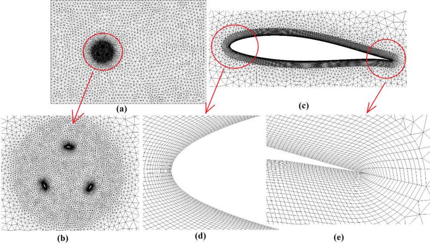
H.M.S.M. Mazarbhuiya, A. Biswas and K. K. Sharma the rotor compared to without blade twist rotor. Beri et al. for pressure linked equation (SIMPLE) algorithm is used to [7] investigated the self-starting property of symmetric couple pressure-velocity terms of URANS equation. NACA 0018 airfoil blade modified at its trailing edge. Standard pressure and second order momentum spatial Trailing edge modification was done by creating a flexible discretization scheme is used. A first order implicit transient portion of the airfoil, which was located at about 70% of the formulation scheme is imposed. A convergence criterion of blade chord length. Two dimensional unsteady flow analysis 10-3 is imposed for continuity, velocity and turbulent revealed that modified airfoil blade profile had better self- properties. The time step size (∆t) is calculated using Eq. starting at low tip speed ratios (TSR) compared to prominent (1). cambered airfoil NACA 2415. Sobhani et al. [8] used blades for VAWT having cavities instead of conventional blades. t (1) 180 They observed a 25% increase in average efficiencies of the rotor with blade cavity. The combination of semicircular where ω denotes angular velocity of H-Darrieus VAWT. dimple and gurney flap was also used to investigate the The number of time step is 1800, which completes five turbine performance. Ismail and Vijayaraghavan used the complete rotation of the turbine. Maximum iteration per combination of dimple and gurney flap and obtained time steps is retained as 20. The boundary conditions like maximum average tangential force for VAWT [9]. Due to velocity inlet, pressure outlet and symmetry to the sidewall capability of maximizing the tangential force its use (gurney boundaries are imposed on the computational model as flap) might be apparent at low tip speed range. Bianchini et shown in Fig. 1. This rectangular model consists of one al. [10] recommended gurney flap at inner side of airfoil stationary and one rotating domain. The radius of rotating which extracted better torque at downwind half of turbine domain is enlarged to double of the radius of the turbine. revolution. A parametric observation was also carried out to Distance between inlet boundary condition and the turbine select an optimized geometrical model for urban center is 10r, and the whole length of the computational environment [11]. Roh et al.[12] also reported that variation domain is 30r. Blades are created in such a way that of blade profile influence the turbine power. A three bladed aerodynamic moment center remains at 25% of chord H-Darrieus turbine has better aerodynamic performance than length. other blade configurations [13]. Design and operational parameters impact the performance of H-Darrieus VAWT. Increasing the aerodynamic performance of VAWT with symmetrical and asymmetrical blade at low wind speed is a great challenge as faced by previous researchers. In this paper to design an effective H-Darrieus VAWT for low wind speed of urban location, a six-digit asymmetric airfoil, NACA 63-415 is selected. Twist is made at the trailing edge of the airfoil blade. It is anticipated that twist at the trailing edge would accelerate the flow at the blade trailing edge, which is otherwise slow and on the verge of separation. And which might increase the aerodynamic performance of the blades and the turbine as a whole. In this regard, a two dimensional Figure 1. 2D H-Darrieus VAWT domain. numerical simulation is done for performance optimization The detail geometrical description of the VAWT is given in of the considered H-Darrieus VAWT with trailing edge Table 1. blade twists. Table 1. Details of the VAWT geometrical dimensions 2. Numerical and geometrical modelling Numerical simulation of H-Darrieus VAWT using Fluent Blade profile NACA 63-415 CFD software is performed using finite volume method to solve the unsteady Reynolds average Naiver Stoke Number of blades (N) 3 (URANS) equation. A viscous model consisting of four Blade chord length (c) 0.05 m equations is used to simulate the low wind speed flow across the turbine. The four equations transition SST model has Spoke-Blade connection 25% of c capability to capture the underlying flow physics associated Turbine diameter (D) 0.5 m with VAWT and has a good agreement with experimental Turbine solidity (σ) 0.3 results [14–16]. In VAWT simulation a flow transition from laminar to turbulent is present and hence it is suitable to use Wind speed (U) 6.0 m/s transition SST model [17]. The four equation model is based The details of computational domain and mesh is shown in on the coupling of SST-kω transport equations with addition Fig. 2. The aerodynamic performance of NACA 63-415 is of another two transport equations. A semi implicit method better [18] and hence it is selected for the turbine blade EAI Endorsed Transactions on 2 Energy Web 05 2020 - 07 2020 | Volume 7 | Issue 28 | e5
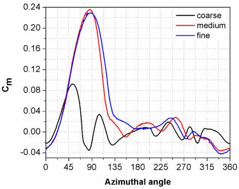
A 2D Numerical Simulation of Blade Twist Effect on the Aerodynamic Performance of an Asymmetric Blade Vertical Axis Wind Turbine in Low Wind speed creation. A sliding mesh motion technique is used to continuity equation Eq. (2), x-momentum Eq. (3) and y- compute the relative motion between rotating and stationary momentum Eq. (4) are solved to calculate the performance domain, which is recommended for time accurate solution of the present turbine using ANSYS FLUENT CFD [19]. These two domains are bounded by an interface. software. Different element size is used on computational domain (airfoil, rotating zone and stationary zone) to ensure the mesh quality and finalize the element size by grid . V 0 (2) independence test. An unstructured triangular mesh is used u p xx yx for the rotating and stationary domain whereas structural mesh is used near the airfoils periphery. A viscous sub-layer t . uV x x y (3) is generated on the airfoil boundary, which is resolved using v p yy xy inflation layers near the airfoil boundary. An inflation zone having 25 number of layers, 0.02 mm first layer thickness t . vV y y x (4) and growth rate of 1.1 is used. Governing equations namely Figure 2. Computational domain and grid: (a) Domain and grid for VAWT, (b) grid near the rotating cell zone, (c) grid near the airfoil, (d) airfoil leading edge, (e) airfoil trailing edge. 3. Sensitivity and validation Cp is obtained between the 4th and 5th turbine revolution. Similar trend of variation in Cp is also reported by For unsteady simulation study, it is necessary to identify Rezaeiha et al. [20]. The angular velocity (ω) for the the number of time steps, which is customarily classified corresponding λ is calculated using the Eq. 5. in terms of turbine revolutions. Unnecessarily excess revolution of turbine in unsteady simulation consumes = (5) 2 lots of memory from the computer system, which is a very time-consuming process and increase the project cost as well. In the present simulation of the considered wind Table 2. Details of grids used in VAWT turbine, five numbers of revolutions are considered. The relative change of Cp with respect to the number of revolutions of the turbine is shown in Fig. 3. With starting Grid size No of elements of the turbine, the change of Cp is maximum which is visible up to the 4th revolution. A significant over Coarse 22230 estimation of turbine performance would be the reason Medium 130512 during data sampling. A very little deflection (0.06%) in EAI Endorsed Transactions on 3 Energy Web 05 2020 - 07 2020 | Volume 7 | Issue 28 | e5
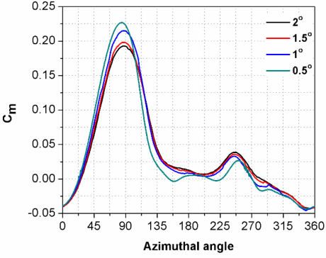
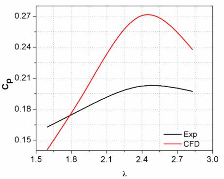
H.M.S.M. Mazarbhuiya, A. Biswas and K. K. Sharma Fine 233154 Figure 4. Variation of Cm with azimuthal position for three grid resolution. The average Cp of 5th revolution of turbine is considered Due to increase in resolution of grids near airfoils for further calculations. In order to ensure the quality of boundary, there would be less overestimation of grid for VAWT, grid sensitivity analysis is conducted for performance in viscous sub-layer zone of the airfoil and three types of grids as described in Table 2. hence a notable increase in Cm is recorded. The change in Cm is negligible for further refinement in grid resolution from medium to fine. Based on this grid sensitivity test a medium grid is selected for further simulation. In order to investigate the sensitivity of different time step size, simulations are performed for azimuthal increments in the range 0.5⁰ to 2⁰. When the azimuthal increment is refined from 2⁰ to 1.5⁰, it results in 0.9% variation in C m. Further refinement of azimuthal increment to 1⁰ and 0.5⁰ results in 0.5% and 0.3% variation in Cm, respectively. The change in Cm with azimuthal position for different azimuthal increment is shown in Fig.5. Figure 3. Relative change of Cp with respect to turbine revolutions The resolution of grids is systematically increased near the airfoils and the rotating zone. This process of grid sensitivity test is used widely in CFD studies. In this study, instantaneous moment coefficient (Cm), lift coefficient (Cl) and drag coefficient (Cd) are monitored. The power coefficient (Cp) of the turbine can be calculated using Eq. 6. C p Cm (6) Figure 5. Variation of Cm with azimuthal angle for various azimuthal increment. The variation of Cm with azimuthal position for last revolution of turbine for a single blade is plotted in Fig. 4 A major change in Cm is observed towards upwind for different grid sizes. position. Although the peak Cm is achieved at upwind position for 0.5⁰ azimuthal increment but the average C m is less due to negative Cm achieved at 150⁰ and 220⁰ azimuthal position. From this investigation, it is observed that if azimuthal increment is reduced then simulation takes more time and computational memory. Hence, for present study an azimuthal increment of 1⁰ is preferred due to an economical computational time. Moreover, the variation in Cm is very less (0.3%) compared to 0.5 ⁰ azimuthal increment. In order to ensure the accuracy of numerical results, a validation study is performed. The C p value calculated from numerical simulation is compared with experimental results of Mazarbhuiya et al. [21] as shown in Fig. 6. The trend of the CFD results is matched with the experimental results. However, the overestimation in CFD results is due to neglecting the combined effect of the tip loss, struts’ drag on the blades and due to the 2D simulation model, which is also reported in literature [22]. Also the maximum over- EAI Endorsed Transactions on 4 Energy Web 05 2020 - 07 2020 | Volume 7 | Issue 28 | e5
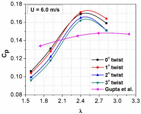
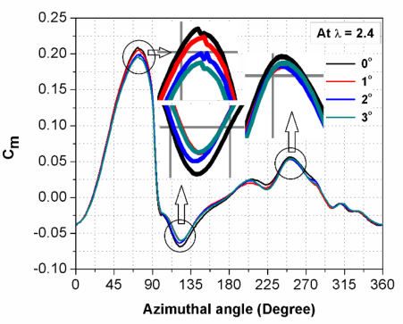
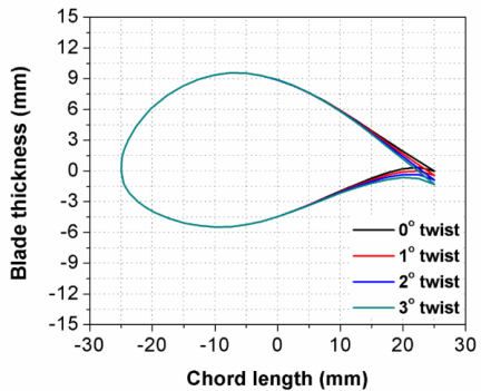
A 2D Numerical Simulation of Blade Twist Effect on the Aerodynamic Performance of an Asymmetric Blade Vertical Axis Wind Turbine
in Low Wind speed

estimation in the present validation is less compared to the In the present investigation 0⁰-3⁰ blade twist has been
validation performed by previous researchers [19,22–24]. considered and the thickness of the airfoil is considered to
It is found from these literatures that the root mean square be 30% as being the optimum [21]. The variation of Cp
error (RMSE) are 25%, 6.8%, 7% and 8.5% in their against different tip speed ratio (TSR) is shown in Fig. 8
validations, whereas in the present validation the RMSE is for different twist angles and also validated the trend of
only 4.22%, which is less compared to the published the curve with [25]. The variations in TSR range occur
results of [19,22–24], and therefore it shows the accuracy due to different solidities of the turbines. Generally,
of the present CFD results. The RMSE is obtained using turbines with symmetric airfoils show better performance
Eq.7 [25]. in higher wind speed (U ˃ 6.0 m/s). But, in the present
 paper investigation has been performed considering built
 ∑
 =1( − )
 2 environment, which has less wind speed (U ≤ 6.0 m/s)
 = √ (7) and in this situation self-starting problem of turbine is

 raised, which can be overcome by using asymmetric
 airfoils [28,29]. Also in real city condition i.e. in urban
 area, the average wind speed can be lower than 6.0 m/s.
 However, asymmetric H-Darrieus turbine can still
 function in suitable locations having higher wind speed
 like those which have accelerated shear layers, for e.g.
 rooftops of high rise buildings and also the developed
 passage that links the areas of positive and negative
 pressure [30]. Although, the wind speed in real city
 condition is less, which also depends upon its
 geographical location, in well planned cities there are
 certain locations where the magnitude of wind speed can
 be brought to a higher value than the average wind speed
 of the city. Some of such locations where it would be
 possible are: (a) on rooftops [31], (b) in between two
 buildings [32], (c) inside through building opening[33],
 (d) on building’s skin [34]. The increased wind speeds in
 such locations are found to be 5.85 m/s [35], 5.5 m/s [36],
Figure 6. Validation of CFD results with established 5.25 m/s [37], which are close to the wind speed
 experimental results [21]. investigated in the present work.

4. Results and discussion
A thorough numerical investigation has been carried out
to determine the performance of asymmetric NACA 63-
415 blade VAWT with different trailing edge blade twist
angle shown in Fig. 7.

 Figure 8. Variations of Cp with TSR for different
 degree of blade twist turbine and also compared with
 existing results [27].

 A minor improvement in performance in terms of
 maximum Cp is visible at 1⁰ twist at TSR 2.4 and this
 Figure 7. Airfoil twist angles used for present 2D improvement is more visible with further increase in TSR.
 numerical simulation. Further increase in blade twist decrease Cp of the turbine.
 Although the difference in Cp is comparatively less, for a

 EAI Endorsed Transactions on
 5 Energy Web
 05 2020 - 07 2020 | Volume 7 | Issue 28 | e5
H.M.S.M. Mazarbhuiya, A. Biswas and K. K. Sharma

bigger configuration of turbine with same aspect ratio the 5. Conclusions
same will proportionately have a sizable difference in
performance. Gupta et al.[27] investigated the An aerodynamic performance is carried out using 2D
performance of H-Darrieus VAWT considering numerical simulation for different trailing edge blade
symmetrical airfoil with trailing edge blade twist. Their twists (1⁰-3⁰). Detailed insights of blade twist effect are
results are compared with present results. The power obtained by analyzing important aerodynamic parameters
coefficient of the present turbine having asymmetric at low operating wind speed 6.0 m/s. The major
airfoil with trailing edge blade twist is found better conclusions are summarized as below-
compared to the turbine having symmetrical airfoil with (a) A maximum power coefficient of 0.171 is
trailing edge blade twist as seen in Fig. 8. obtained at TSR 2.4 for 1⁰ blade twist turbine and
 with further increase in TSR, power coefficient
 of 1⁰ blade twist turbine is still greater than other
 blade twist turbines. Thus, the asymmetric blade
 H-Darrieus turbine with 1⁰ blade twist has
 overall higher aerodynamic performance.
 (b) Although, a minor increment is achieved with 1 ⁰
 blade twist but, further increase in blade twist
 drastically reduces the turbine performance.
 (c) A minor difference in moment coefficient is
 noticed between 0⁰ and 1⁰ blade twist turbine,
 although the average moment coefficient is
 higher for 1⁰ blade twist turbine in many
 azimuthal ranges.
 (d) The present study shows that blade twist should
 be very low for low wind speed application of H-
 Darrieus VAWT.
 Figure 9. Variations of Cm with θ for different degree
 of blade twist turbine. Acknowledgements.
The variation of Cm with azimuthal angle (θ) for different Author would like to thank and acknowledge the computational
trailing edge blade twist angle is shown in Fig. 9. A Lab facility, Department of Mechanical Engineering, NIT
marginal increase in Cm is visible for azimuthal angle 75⁰ Silchar, India.
at 0⁰ twist but at azimuthal position 124⁰ the value of Cm is
lower compared to 1⁰ twist turbine and the average Cm is
higher for 1⁰ twist turbine, which results in increase in C p References
for this turbine at TSR 2.4 (Fig.8). The 0 ⁰ blade twist has
positive maximum and negative maximum C m at 75⁰ and [1] Bouzaher MT, Hadid M. Numerical Investigation of a
 Vertical Axis Tidal Turbine with Deforming Blades.
124⁰ azimuthal position shown in Fig. 9. The values of
 Arab J Sci Eng 2017;42:2167–78. doi:10.1007/s13369-
average Cm for all turbine configuration is given in Table 017-2511-5.
3. [2] Bouzaher MT, Hadid M, Semch-Eddine D. Flow
 control for the vertical axis wind turbine by means of
 flapping flexible foils. J Brazilian Soc Mech Sci Eng
Table 3. Details of average moment coefficient (Cm) 2017;39:457–70. doi:10.1007/s40430-016-0618-3.
for different turbine configurations. [3] Bouzaher MT, Guerira B, Hadid M. Performance
 analysis of a vertical axis tidal turbine with flexible
 blades. J Mar Sci Appl 2017;16:73–80.
 doi:10.1007/s11804-017-1391-0.
 Turbine configuration Average Cm
 [4] Bouzaher MT, Drias N, Guerira B. Improvement of
 No blade twist turbine (0⁰) 0.023442722 Energy Extraction Efficiency for Flapping Airfoils by
 Using Oscillating Gurney Flaps. Arab J Sci Eng
 1⁰ blade twist turbine 0.02366121 2019;44:809–19. doi:10.1007/s13369-018-3270-7.
 2⁰ blade twist turbine 0.022786319 [5] Gupta R, Biswas A. Computational fluid dynamics
 analysis of a twisted three-bladed H-Darrieus rotor. J
 3⁰ blade twist turbine 0.022387913 Renew Sustain Energy 2010;2. doi:10.1063/1.3483487.
 [6] Biswas A, Gupta R. Unsteady aerodynamics of a twist
 bladed H-Darrieus rotor in low Reynolds number flow.
At 252⁰ azimuthal position there is a negligible increase in J Renew Sustain Energy 2014;6.
Cm for 0⁰ twist turbine. Hence, at downwind position doi:10.1063/1.4878995.
effect of blade twist is negligible at low wind speed. The [7] Beri H, Yao Y. Numerical simulation of unsteady flow
 to show self-starting of vertical axis wind turbine using
results at the other two twist angles lie in between the 0⁰ &
 fluent. J Appl Sci 2011;11:962–70.
1⁰ blade pitch results.

 EAI Endorsed Transactions on
 6 Energy Web
 05 2020 - 07 2020 | Volume 7 | Issue 28 | e5
A 2D Numerical Simulation of Blade Twist Effect on the Aerodynamic Performance of an Asymmetric Blade Vertical Axis Wind Turbine
in Low Wind speed

 doi:10.3923/jas.2011.962.970. axis wind turbine with different series airfoil shapes.
[8] Sobhani E, Ghaffari M, Maghrebi MJ. Numerical Renew Energy 2018;126:801–18.
 investigation of dimple effects on darrieus vertical axis doi:10.1016/j.renene.2018.02.095.
 wind turbine. Energy 2017;133:231–41. [24] Gosselin R, Dumas G, Boudreau M. Parametric study
 doi:10.1016/j.energy.2017.05.105. of H-Darrieus vertical-axis turbines using CFD
[9] Ismail MF, Vijayaraghavan K. The effects of aerofoil simulations. J Renew Sustain Energy 2016;8.
 profile modification on a vertical axis wind turbine doi:10.1063/1.4963240.
 performance. Energy 2015;80:20–31. [25] Mazarbhuiya HMSM, Biswas A, Sharma KK. Blade
 doi:10.1016/j.energy.2014.11.034. thickness effect on the aerodynamic performance of an
[10] Bianchini A, Balduzzi F, Di Rosa D, Ferrara G. On the asymmetric NACA six series blade vertical axis wind
 use of Gurney Flaps for the aerodynamic performance turbine in low wind speed. Int J Green Energy
 augmentation of Darrieus wind turbines. Energy 2020;17:171–9. doi:10.1080/15435075.2020.1712214.
 Convers Manag 2019;184:402–15. [26] Howell R, Qin N, Edwards J, Durrani N. Wind tunnel
 doi:10.1016/j.enconman.2019.01.068. and numerical study of a small vertical axis wind
[11] Svorcan J, Stupar S, Komarov D, Peković O, Kostić I. turbine. Renew Energy 2010;35:412–22.
 Aerodynamic design and analysis of a small-scale doi:10.1016/j.renene.2009.07.025.
 vertical axis wind turbine. J Mech Sci Technol [27] Gupta R, Biswas A. Performance measurement of a
 2013;27:2367–73. doi:10.1007/s12206-013-0621-x. twisted three-bladed airfoil-shaped H-rotor
[12] Roh SC, Kang SH. Effects of a blade profile, the 2010;1:279–300.
 Reynolds number, and the solidity on the performance [28] Singh MA, Biswas A, Misra RD. Investigation of self-
 of a straight bladed vertical axis wind turbine. J Mech starting and high rotor solidity on the performance of a
 Sci Technol 2013;27:3299–307. doi:10.1007/s12206- three S1210 blade H-type Darrieus rotor. Renew
 013-0852-x. Energy 2015;76:381–7.
[13] Chen Y, Lian Y. Numerical investigation of vortex doi:10.1016/j.renene.2014.11.027.
 dynamics in an H-rotor vertical axis wind turbine. Eng [29] Batista NC, Melício R, Mendes VMF, Calderón M,
 Appl Comput Fluid Mech 2015;9:21–32. Ramiro A. On a self-start Darrieus wind turbine: Blade
 doi:10.1080/19942060.2015.1004790. design and field tests. Renew Sustain Energy Rev
[14] Menter FR, Kuntz M, Langtry R. Ten Years of 2015;52:508–22. doi:10.1016/j.rser.2015.07.147.
 Industrial Experience with the SST Turbulence Model. [30] Ayhan D, Saǧlam A. A technical review of building-
 Turbul Heat Mass Transf 4 2003;4:625–32. mounted wind power systems and a sample simulation
 doi:10.4028/www.scientific.net/AMR.576.60. model. Renew Sustain Energy Rev 2012;16:1040–9.
[15] Menter FR, Langtry RB, Likki SR, Suzen YB, Huang doi:10.1016/j.rser.2011.09.028.
 PG, Völker S. A Correlation-Based Transition Model [31] Abohela I, Hamza N, Dudek S. Effect of roof shape,
 Using Local Variables—Part I: Model Formulation. J wind direction, building height and urban configuration
 Turbomach 2006;128:413. doi:10.1115/1.2184352. on the energy yield and positioning of roof mounted
[16] Langtry RB, Menter FR, Likki SR, Suzen YB, Huang wind turbines. Renew Energy 2013;50:1106–18.
 PG, Völker S. A Correlation-Based Transition Model doi:10.1016/j.renene.2012.08.068.
 Using Local Variables—Part II: Test Cases and [32] Blocken B, Stathopoulos T, Carmeliet J. Wind
 Industrial Applications. J Turbomach 2006;128:423. Environmental Conditions in Passages between Two
 doi:10.1115/1.2184353. Long Narrow Perpendicular Buildings. J Aerosp Eng
[17] Almohammadi KM, Ingham DB, Ma L, Pourkashan M. 2008;21:280–7. doi:10.1061/(ASCE)0893-
 Computational fluid dynamics (CFD) mesh 1321(2008)21.
 independency techniques for a straight blade vertical [33] Li QS, Shu ZR, Chen FB. Performance assessment of
 axis wind turbine. Energy 2013;58:483–93. tall building-integrated wind turbines for power
 doi:10.1016/j.energy.2013.06.012. generation. Appl Energy 2016;165:777–88.
[18] Mohamed MH, Ali AM, Hafiz AA. CFD analysis for doi:10.1016/j.apenergy.2015.12.114.
 H-rotor Darrieus turbine as a low speed wind energy [34] Park J, Jung HJ, Lee SW, Park J. A new building-
 converter. Eng Sci Technol an Int J 2015;18:1–13. integrated wind turbine system utilizing the building.
 doi:10.1016/j.jestch.2014.08.002. Energies 2015;8:11846–70. doi:10.3390/en81011846.
[19] Hashem I, Mohamed MH. Aerodynamic performance [35] Arteaga-López E, Ángeles-Camacho C, Bañuelos-
 enhancements of H-rotor Darrieus wind turbine. Energy Ruedas F. Advanced methodology for feasibility
 2018;142:531–45. doi:10.1016/j.energy.2017.10.036. studies on building-mounted wind turbines installation
[20] Rezaeiha A, Kalkman I, Blocken B. Effect of pitch in urban environment: Applying CFD analysis. Energy
 angle on power performance and aerodynamics of a 2019;167:181–8. doi:10.1016/j.energy.2018.10.191.
 vertical axis wind turbine. Appl Energy 2017;197:132– [36] Dilimulati A, Stathopoulos T, Paraschivoiu M. Wind
 50. doi:10.1016/j.apenergy.2017.03.128. turbine designs for urban applications: A case study of
[21] Mazarbhuiya HMSM, Biswas A, Sharma KK. shrouded diffuser casing for turbines. J Wind Eng Ind
 Performance investigations of modified asymmetric Aerodyn 2018;175:179–92.
 blade H-Darrieus VAWT rotors. J Renew Sustain doi:10.1016/j.jweia.2018.01.003.
 Energy 2018;033302. doi:10.1063/1.5026857. [37] Sotoudeh F, Kamali R, Mousavi SM. Field tests and
[22] Raciti Castelli M, Englaro A, Benini E. The Darrieus numerical modeling of INVELOX wind turbine
 wind turbine: Proposal for a new performance application in low wind speed region. Energy
 prediction model based on CFD. Energy 2011;36:4919– 2019;181:745–59. doi:10.1016/j.energy.2019.05.186.
 34. doi:10.1016/j.energy.2011.05.036.
[23] Wang Y, Shen S, Li G, Huang D, Zheng Z.
 Investigation on aerodynamic performance of vertical

 EAI Endorsed Transactions on
 7 Energy Web
 05 2020 - 07 2020 | Volume 7 | Issue 28 | e5
You can also read