Impact Performance Evaluation of a Crash Cushion Design Using Finite Element Simulation and Full-Scale Crash Testing - MDPI

Page created by Max Burgess
 
CONTINUE READING
Impact Performance Evaluation of a Crash Cushion Design Using Finite Element Simulation and Full-Scale Crash Testing - MDPI
safety
Article
Impact Performance Evaluation of a Crash Cushion
Design Using Finite Element Simulation and
Full-Scale Crash Testing
Murat Büyük 1 , Ali Osman Atahan 2, *           and Kenan Kurucuoğlu 3
 1    Department Faculty of Engineering and Natural Sciences, Sabanci University, Main Campus, İstanbul 34956,
      Turkey; muratbuyuk@sabanciuniv.edu
 2    Department of Civil Engineering, Istanbul Technical University, Ayazaga Campus, İstanbul 34469, Turkey
 3    Ulukur Plastic Traffic Products, İstanbul 34870, Turkey; info@ulukur.com
 *    Correspondence: atahana@itu.edu.tr
                                                                                                      
 Received: 22 August 2018; Accepted: 25 October 2018; Published: 1 November 2018                      

 Abstract: Crash cushions are designed to gradually absorb the kinetic energy of an impacting vehicle
 and bring it to a controlled stop within an acceptable distance while maintaining a limited amount of
 deceleration on the occupants. These cushions are used to protect errant vehicles from hitting rigid
 objects, such as poles and barriers located at exit locations on roads. Impact performance evaluation
 of crash cushions are attained according to an EN 1317-3 standard based on various speed limits and
 impact angles. Crash cushions can be designed to absorb the energy of an impacting vehicle by using
 different material deformation mechanisms, such as metal plasticity supported by airbag folding
 or damping. In this study, a new crash cushion system, called the ulukur crash cushion (UCC), is
 developed by using linear, low-density polyethylene (LLDPE) containers supported by embedded
 plastic energy-absorbing tubes as dampers. Steel cables are used to provide anchorage to the design.
 The crashworthiness of the system was evaluated both numerically and experimentally. The finite
 element model of the design was developed and solved using LS-DYNA (971, LSTC, Livermore, CA,
 USA), in which the impact performance was evaluated considering the EN 1317 standard. Following
 the simulations, full-scale crash tests were performed to determine the performance of the design
 in containing and redirecting the impacting vehicle. Both the simulations and crash tests showed
 acceptable agreement. Further crash tests are planned to fully evaluate the crashworthiness of the
 new crash cushion system.

 Keywords: crash cushion; crash test; simulation; LS-DYNA; EN 1317; road safety; energy absorption;
 linear, low-density polyethylene

1. Introduction
      Traffic and road safety is a serious concern worldwide, and multi-phased research has been
undertaken in recent years. The United Nations General Assembly has made an important initiative to
reduce the fatality rate in traffic accidents around the world by 50% and provided funds for research.
In this context, Turkey has prepared a 10-year vision program covering traffic education and training,
safety and enforcement, health and emergency assistance initiatives, and the improvement of traffic
safety with engineering measures [1,2]. This program has been implemented by Ministries of Education,
Interior, Health, and Transportation. Since 2010, serious steps have been taken regarding traffic safety
in Turkey. These advances include speed control using smart detection systems, the enforcement of
traffic rules through cameras, the reduction of arrival times of ambulances in an accident site, and
providing traffic safety culture to students of all ages. These undertakings have resulted in a 10%

Safety 2018, 4, 48; doi:10.3390/safety4040048                                     www.mdpi.com/journal/safety
Impact Performance Evaluation of a Crash Cushion Design Using Finite Element Simulation and Full-Scale Crash Testing - MDPI
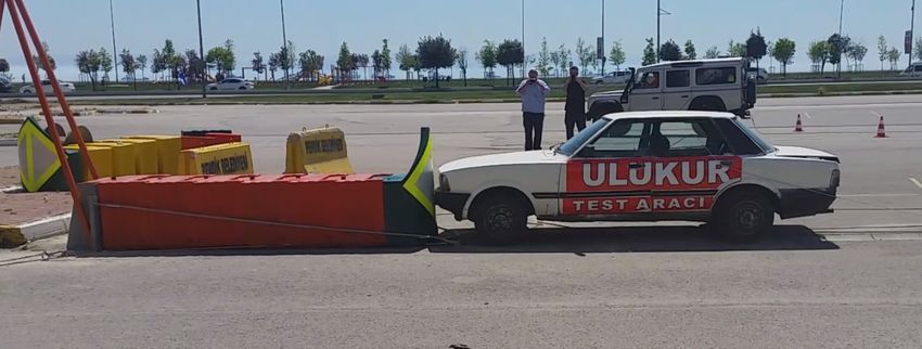
Safety 2018, 4, 48                                                                                                     2 of 11
Safety 2018, 4, x FOR PEER REVIEW                                                                                       2 of 11

decrease
statisticalindata,
              fatal the
                     accidents  in Turkey;
                         level of             however,
                                    achievement            according
                                                      is not            to statistical
                                                               at the desired     level data,
                                                                                         of 15%.the level
                                                                                                     Lack ofofachievement
                                                                                                               road restraintis
not  at the desired   level  of 15%.    Lack  of  road   restraint  system
system utilization is one of the areas that needs to be improved [1].         utilization   is one   of the areas  that  needs
to beCrash
       improved     [1]. are widely used in developed countries to protect vehicles against impacts with
              cushions
fixed, sharp, narrow,are
      Crash   cushions     andwidely     used inlocated
                                rigid objects      developed     countries
                                                            at road           to protect
                                                                     exit locations,       vehicles
                                                                                        tool   booths, against  impacts
                                                                                                         workzones,       with
                                                                                                                        barrier
fixed,  sharp,  narrow,    and  rigid   objects  located    at road  exit locations,    tool  booths,
ends, and trees [3,4]. As shown in Figure 1, collision with unprotected objects increases the severity   workzones,     barrier
ends,   and trees
of accidents    and[3,4]. As shown
                       results          in Figure
                                in fatalities.      1, collisiontowith
                                                  According              unprotected
                                                                    predictions          objects
                                                                                    by the          increases
                                                                                               Turkish         the severity
                                                                                                          statistics         of
                                                                                                                      institute
accidents   and   results  in fatalities.  According      to predictions    by  the  Turkish     statistics
(TUIK), the number of fixed object accidents is on the rise, which creates concern for road-safety          institute  (TUIK),
the  number
targets  set byofthe
                   fixed  objectGovernment
                      Turkish     accidents is [5].
                                                  on the   rise,
                                                       Crash      which creates
                                                               cushions   in generalconcern     for road-safety
                                                                                        are designed      to slow targets
                                                                                                                   down and set
by  the  Turkish   Government        [5]. Crash    cushions    in general   are  designed
contain the impacting vehicle in a controlled way by absorbing its kinetic energy. The Istanbulto  slow  down    and   contain
the  impacting Municipality
Metropolitan      vehicle in a controlled     way by
                                   (IMM), which           absorbing its
                                                      is responsible    forkinetic
                                                                             trafficenergy.    The Istanbul
                                                                                     safety within      the cityMetropolitan
                                                                                                                  of Istanbul,
Municipality
expressed interest in utilizing low-cost and nationally developed crash cushions in Istanbulinterest
                (IMM),    which   is responsible    for traffic  safety within   the  city of  Istanbul,   expressed    due to
in utilizing
budget        low-cost[1].
          constraints    and nationally developed crash cushions in Istanbul due to budget constraints [1].

                         Figure 1.
                         Figure 1. Severity
                                   Severity of
                                            of road accidents with
                                               road accidents with narrow
                                                                   narrow and
                                                                          and rigid
                                                                              rigid objects.
                                                                                    objects.

     The aim of  of this
                     this project
                           projectis,
                                    is,therefore,
                                        therefore,totodevelop
                                                        develop a new
                                                                   a newhybrid
                                                                           hybridcrash cushion
                                                                                    crash        system,
                                                                                           cushion        called
                                                                                                     system,      the
                                                                                                              called
ulukur   crash  cushion    (UCC),   made     out of linear, low-density   polyethylene    (LLDPE)
the ulukur crash cushion (UCC), made out of linear, low-density polyethylene (LLDPE) containers     containers   and
steelsteel
and   plates  for the
           plates  forIMM.     In this
                        the IMM.     In respect, the UCC
                                         this respect,       will have
                                                       the UCC          low initial
                                                                  will have         maintenance
                                                                              low initial          and repair
                                                                                          maintenance           costs
                                                                                                         and repair
with with
costs  reusable    parts.parts.
             reusable        The The
                                  crashworthiness
                                        crashworthiness of the   system
                                                            of the  systemis isevaluated
                                                                                evaluatedboth
                                                                                            both numerically
                                                                                                  numerically and
experimentally. The  The finite
                           finite element
                                  element model
                                              model ofof the UCC is developed, and impact performance is
analyzed using LS-DYNA in accordance with TSEN 1317 crash testing standard [6,7].              [6,7]. Following the
simulations, full-scale crash tests were performed to validate  validate the
                                                                          the computer
                                                                               computer simulation
                                                                                          simulation results.
                                                                                                       results. Both
the simulations and crash tests show acceptable agreement. Further crash tests are planned to fully
               crashworthiness of
evaluate the crashworthiness        of the
                                        the new
                                             new crash
                                                  crash cushion
                                                         cushion system.
                                                                   system.

2. Details of Ulukur Crash Cushion Developed
      Ulukur crash cushion (UCC) design is composed of linear, low density polyethylene (LLDPE)
containers, energy-absorbing tubes, steel cables, lower plates, and            and back
                                                                                     back support
                                                                                            support plate.
                                                                                                        plate. Geometrical
                                                                                                                Geometrical
details of these materials
                  materials areare provided
                                   providedin   inFigure
                                                   Figure2.2.Containers
                                                                 Containersare  areproduced
                                                                                    producedusing   usingLLDPE,
                                                                                                           LLDPE,    since
                                                                                                                   since    it
                                                                                                                         it is
is a dependableand
a dependable       andcost-effective
                         cost-effectivematerial
                                          materialthatthatcould
                                                            couldsustain
                                                                    sustain large
                                                                              large deformations,
                                                                                      deformations, endure dynamic  dynamic
forces,
forces, and
         andabsorb
               absorb kinetic energy
                         kinetic       of the
                                  energy    of impacting     vehiclevehicle
                                                 the impacting        withoutwithout
                                                                                  crack formation.      Detailed technical
                                                                                            crack formation.        Detailed
information   about LLDPE
technical information     aboutcanLLDPE
                                   be foundcaninbea found
                                                    study by in aCozzi
                                                                  studyetbyal.Cozzi
                                                                               [8]. The   measurements
                                                                                      et al.                 for the LLDPE
                                                                                              [8]. The measurements       for
containers
the LLDPEare     500 mmare
             containers        500×mm
                            long     800 long
                                           mm ×wide     × 710
                                                   800 mm     wide     710×
                                                                 mm×tall    mm 8 mmtall thick.
                                                                                        × 8 mmInthick.
                                                                                                     addition,   250 mm250
                                                                                                           In addition,    in
diameter,  460 mm 460
mm in diameter,       longmmenergy-absorbing      tubes made
                                long energy-absorbing             outmade
                                                               tubes   of LLDPE     areLLDPE
                                                                               out of     utilizedareinside   the containers
                                                                                                        utilized  inside the
to improvetothe
containers        crash performance
                improve                    of the design.
                           the crash performance       of the50    mm in
                                                                design.  50diameter       holes are
                                                                             mm in diameter            provided
                                                                                                    holes          on tubes
                                                                                                           are provided    on
to allow  controlled    air release.  The   number      of tubes   varied   based    on   the  container
tubes to allow controlled air release. The number of tubes varied based on the container type. In            type.  In other
words,  as shown
other words,        in Figure
                as shown       2, the lead
                            in Figure       container
                                        2, the           with a shield
                                                lead container     with aincluded     two tubes,
                                                                            shield included          whereas
                                                                                                   two  tubes, all the other
                                                                                                                 whereas   all
standard
the other containers    included four
           standard containers            tubes.
                                    included       This
                                                four     is intended
                                                      tubes.            to provide
                                                               This is intended     toaprovide
                                                                                         soft nose-section      for vehicles
                                                                                                    a soft nose-section   for
with  low-energy
vehicles           impacts. Asimpacts.
          with low-energy         the impactAs energy    increases,
                                                 the impact           so do
                                                                 energy       the energy
                                                                          increases,     so absorption
                                                                                             do the energy capacities  of the
                                                                                                                 absorption
UCC    design.
capacities      Material
            of the        properties
                   UCC design.         of LLDPE
                                    Material         are provided
                                               properties     of LLDPEin Table   1.
                                                                          are provided       in Table 1.
Impact Performance Evaluation of a Crash Cushion Design Using Finite Element Simulation and Full-Scale Crash Testing - MDPI
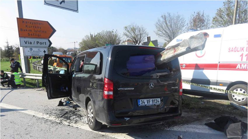
Safety 2018, 4, 48                                                                                                 3 of 11
Safety 2018, 4, x FOR PEER REVIEW                                                                                  3 of 11

                                   (a)                                                          (b)

                                   (c)                                                          (d)
     Figure
     Figure 2.
            2. Details
               Details of
                       of ulukur
                          ulukur crash
                                 crash cushion
                                       cushion (UCC)
                                                (UCC)(a)
                                                      (a) internal
                                                           internal view;
                                                                    view;(b)
                                                                          (b) energy
                                                                              energy absorbing
                                                                                     absorbingtube;
                                                                                               tube;(c)
                                                                                                     (c) top
                                                                                                          top
     view; and (d) assembled  crash cushion
     view; and (d) assembled crash cushion.

           1. Material
     Table 1.
     Table     Materialproperties of low-density
                         properties              polyethylene
                                     of low-density           (LLDPE)
                                                     polyethylene     used in
                                                                  (LLDPE)     UCC
                                                                           used in(ulukur crash cushion)
                                                                                   UCC (ulukur    crash
     design [9,10].
     cushion) design [9,10].
                                     Property                     Value     Test Standard
                                        Property                 Value Test Standard
                                Density (kg/m3 ) 3                 935      ASTM D 1505
                                     Density (kg/m )              935   ASTM D 1505
                           Modulus of Elasticity (MPa)             724       ASTM D 790
                              Modulus   of Elasticity (MPa)
                                    Toughness                     724
                                                                    69  ASTM   D 790
                                                                            ASTM   D 2240
                                       Toughness
                              Yield Strength (MPa)                 69
                                                                    18  ASTM  D
                                                                             ASTM2240
                                                                                    D 638
                                  Yield Strength
                           Vicat Softening         (◦ C)
                                           Temp.(MPa)              18
                                                                   115  ASTM   D 638
                                                                            ASTM   D 1525
                               Vicat Softening
                             Brittleness        (◦ C) (°C)
                                         Temp.Temp.                −75 ASTMASTM
                                                                  115         D 1525D 746
                                 Brittleness Temp. (°C)           −75   ASTM D 746

      The UCC design developed in this study is composed of six containers and a frontal shield. The
      The UCC design developed in this study is composed of six containers and a frontal shield. The
 design is actually intended for 110 kph impacts, so the original design with six containers is not altered
design is actually intended for 110 kph impacts, so the original design with six containers is not
 for 50 kph impact. Total length of the design is 3700 mm. The measurements of UCC elements are
altered for 50 kph impact. Total length of the design is 3700 mm. The measurements of UCC
 provided in Figure 2. This design is intended to provide safe containment and redirection for 50 kph
elements are provided in Figure 2. This design is intended to provide safe containment and
 head-on and side impacts. Since UCC has a modular nature, the design could be easily converted to
redirection for 50 kph head-on and side impacts. Since UCC has a modular nature, the design could
 80, 100, or 110 kph impacts by adding more containers, tubes, and steel members. Thus, the length of
be easily converted to 80, 100, or 110 kph impacts by adding more containers, tubes, and steel
 the system can change based on target design speed. As shown in Figure 2, UCC used four 19 mm
members. Thus, the length of the system can change based on target design speed. As shown in
 diameter steel cables (two on the bottom and two on the side), and cables are anchored to steel plates
Figure 2, UCC used four 19 mm diameter steel cables (two on the bottom and two on the side), and
 at both ends. Bottom cables run between two 650 mm wide × 40 mm wide × 25 mm thick steel plates
cables are anchored to steel plates at both ends. Bottom cables run between two 650 mm wide × 40
 located under the containers. This allowed controlled deformation of containers during frontal and
mm wide × 25 mm thick steel plates located under the containers. This allowed controlled
 side vehicle impacts. Two side cables are used to improve lateral stability of the UCC design.
deformation of containers during frontal and side vehicle impacts. Two side cables are used to
improve
 3. TS ENlateral  stability
            1317 Crash      of theStandard
                         Testing   UCC design.
                                           for Crash Cushion Evaluatıon

3. TSToENassess   the performance
           1317 Crash                  of crash for
                          Testing Standard       cushions
                                                     Crash against
                                                             Cushion    vehicle  impacts, Part 3 of EN 1317 standard,
                                                                          Evaluatıon
named “road-restraint systems—part 3: performance classes, impact test acceptance criteria and test
     To assess
methods            thecushions”
            for crash    performance      of crash
                                    is followed   [6].cushions
                                                       According   against
                                                                      to this vehicle
                                                                               standard,impacts,
                                                                                           vehiclesPart   3 of EN
                                                                                                     weighing   900, 1317
                                                                                                                     1300,
standard,     named     “road-restraint    systems—part        3:  performance       classes,  impact
or 1500 kg traveling at speeds of 50, 80, 100, or 110 impact crash cushions in five different approaches.test acceptance
criteria
Figure 3and    test all
           shows     methods
                        possiblefor  crash
                                  test      cushions”described
                                        combinations      is followed     [6]. 1317
                                                                       in EN   According
                                                                                     standardto this
                                                                                                Partstandard,     vehicles
                                                                                                      3 [6]. As shown    in
weighing     900, 1300,  or 1500  kg  traveling   at speeds   of  50,  80, 100,  or 110  impact  crash
Table 2, for 50 kph tests there are only two tests, namely, TC 1.1.50 and TC 4.2.50; a 900 kg passenger  cushions  in five
different  approaches.
car at impact     positionFigure
                             1 and 31300
                                      showskg all  possiblecar
                                               passenger      testatcombinations
                                                                     impact positon   described   in EN 1317
                                                                                          2, respectively,  are standard
                                                                                                                specified.
Part
Both computer simulations and full-scale crash tests on UCC design are performed at 50 and
     3  [6]. As  shown    in Table   2, for 50 kph    tests there   are  only   two  tests,  namely,  TC   1.1.50 kph.TC In
4.2.50; a 900 kg passenger car at impact position 1 and 1300 kg passenger car at impact positon 2,
respectively, are specified. Both computer simulations and full-scale crash tests on UCC design are
Impact Performance Evaluation of a Crash Cushion Design Using Finite Element Simulation and Full-Scale Crash Testing - MDPI
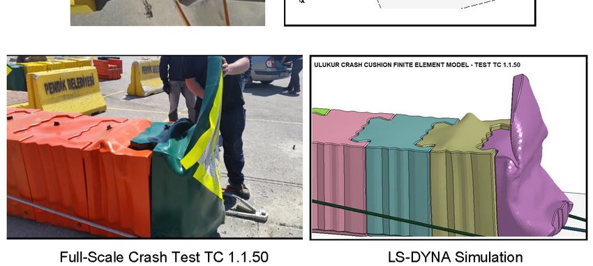
Safety 2018, 4, 48                                                                                                           4 of 11
Safety 2018, 4, x FOR PEER REVIEW                                                                                            4 of 11

other  words,atimpact
performed       50 kph.performance of the
                        In other words,   UCC design
                                        impact       is evaluated
                                               performance  of the using TC 1.1.50
                                                                   UCC design      and TC 4.2.50
                                                                                is evaluated     crash
                                                                                             using TC
tests [6].
1.1.50 and TC 4.2.50 crash tests [6].

                       Figure 3. Crash cushion test approaches in EN 1317 Standard
                                                                          Standard Part
                                                                                   Part 33 [6].
                                                                                           [6].

                        Table 2. Crash testing details for crash cushions in EN 1317 part 3 [6].
                        Table 2. Crash testing details for crash cushions in EN 1317 part 3 [6].
    Test Speed (kph)                                             Acceptance Tests *,,**
   Test Speed (kph)                                              Acceptance Tests * **
               50               TC 1.1.50                                                          TC 4.2.50
             5080                TC  1.1.50
                                TC 1.1.80       TC 1.2.80       TC 2.1.80         TC 3.2.80        TCTC   4.2.50 TC 5.2.80
                                                                                                       4.2.80
             80
              100                TC  1.1.80
                               TC 1.1.100          TC   1.2.80
                                               TC 1.2.100          TC  2.1.80
                                                               TC 2.1.100            TC  3.2.80
                                                                                 TC 3.2.100          TC   4.2.80 TCTC
                                                                                                  TC 4.2.100                5.2.80
                                                                                                                        5.2.100
            100
              110               TC  1.1.100
                               TC 1.1.100         TC   1.2.100
                                               TC 1.3.110          TC 2.1.100
                                                               TC 2.1.100           TC  3.2.100
                                                                                 TC 3.3.110          TC  4.2.100
                                                                                                  TC 4.3.110          TC   5.2.100
                                                                                                                    TC 5.3.110
            110                 TC 1.1.100        TC 1.3.110       TC 2.1.100       TC 3.3.110       TC 4.3.110       TC 5.3.110
     * TC 5.3.110 stands for test crash cushion (TC) approach (5), vehicle (3), and speed (110); ** Vehicles 1, 2, and 3 stand
     *forTC 5.3.110  stands  for test crash cushion
          900 kg, 1300 kg, and 1500 kg, respectively. (TC)  approach   (5), vehicle   (3), and speed   (110);  ** Vehicles   1,
      2, and 3 stand for 900 kg, 1300 kg, and 1500 kg, respectively.
4. Computer Simulation of UCC Design
      Before pursuing costly, full-scale crash testing, a detailed finite element simulation study was
      Beforeon
performed       pursuing     costly,Afull-scale
                   UCC design.                      crash testing,
                                       highly non-linear             a detailed finite element
                                                              and large-deformation                  simulation
                                                                                           finite-element    code study
                                                                                                                   LS-DYNAwas
performed        on   UCC     design.    A     highly    non-linear    and    large-deformation
developed by the livermore software technology corporation (LSTC) was used to model the barrier        finite-element    code
LS-DYNA
and  simulate  developed     by the livermore
                  the vehicle-barrier      impactsoftware
                                                      event [7].technology     corporation
                                                                  Details of the   bridge rail(LSTC)    wasvehicle
                                                                                                 and both     used tomodels
                                                                                                                       model
the explained
are  barrier and      simulate the vehicle-barrier impact event [7]. Details of the bridge rail and both
                   below.
vehicle models are explained below.
4.1. Finite Element Model of UCC Design
      A finite element model of the UCC was developed to assess the crash test performance of
      A finiteThe
the design.       element
                      model, model    of the in
                                 as shown       UCC    was4,developed
                                                   Figure      consistedto ofassess
                                                                               143,063thenodes,
                                                                                           crash 135,389
                                                                                                  test performance
                                                                                                             shell, andof4264
                                                                                                                           the
design.
solid      The model,
        elements.          as shown
                       Shell   elements in represented
                                            Figure 4, consisted
                                                            the LLDPEof 143,063
                                                                           members nodes,
                                                                                        and 135,389   shell, and
                                                                                               steel plates        4264
                                                                                                              of the     solid
                                                                                                                       model,
elements.
while   solidShell   elements
                elements         represented
                            represented       the the
                                                  steelLLDPE
                                                         cables.members
                                                                   The shelland   steel plates
                                                                               elements    of theofLLDPE
                                                                                                    the model,    while solid
                                                                                                             containers   and
elementstubes
internal     represented
                    that arethe   steel cables.
                               expected     to get The
                                                     in shell
                                                         directelements
                                                                 contact of  the vehicles
                                                                          with    LLDPE containers       and internalsevere
                                                                                             and thus experience        tubes
that are expected
deformations       are to  get in direct
                        modeled      with contact      with vehicles
                                             full integration          and thustoexperience
                                                                  formulation       accuratelysevere       deformations
                                                                                                   represent    the complexare
modeled      with    full integration     formulation      to   accurately   represent    the
interactions and behavior. All steel elements were modeled with default element formulation for complex    interactions   and
behavior. All steel
computational              elements were modeled with default element formulation for computational
                    efficiency.
efficiency.
      Since containers are expected to sustain large plastic deformations and possible crushing, a
      Since linear
piecewise      containers
                      plasticare   expected
                                material        to sustain
                                           definition    was large
                                                              used toplastic
                                                                        model  deformations      and possible
                                                                                 the LLDPE elements              crushing,
                                                                                                           [11,12].  Since noa
piecewise
failure       linear plastic
         is expected    in steelmaterial
                                  members, definition    was used
                                                a rigid material     to modelwas
                                                                    modeling     theused
                                                                                     LLDPE      elementsplates
                                                                                            to represent    [11,12].
                                                                                                                  andSince  no
                                                                                                                       cables.
failure
Steel     is expected
       cables             in steel
                were firmly         members,
                                attached    to steela rigid
                                                      platesmaterial    modeling
                                                              at both ends,          wasplates
                                                                              and steel     used were
                                                                                                  to represent
                                                                                                         securedplates    and
                                                                                                                   to ground
cables.unfailing
using     Steel cables    were firmly attached to steel plates at both ends, and steel plates were secured to
                     connections.
groundIn anusing   unfailing
              actual            connections.
                      UCC installation,        connections between the members, such as lower steel plates and
      In  an  actual   UCC    installation,
containers, and steel plates to ground,        connections    between
                                                  are established        thebolts
                                                                     using    members,
                                                                                  and nuts.suchToas  lower steel
                                                                                                  accurately       plates and
                                                                                                               represent   the
containers, and steel plates to ground, are established using bolts and nuts. To accurately represent
the behavior of these connections during full-scale crash testing, CONSTRAINED_SPOTWELD
Impact Performance Evaluation of a Crash Cushion Design Using Finite Element Simulation and Full-Scale Crash Testing - MDPI
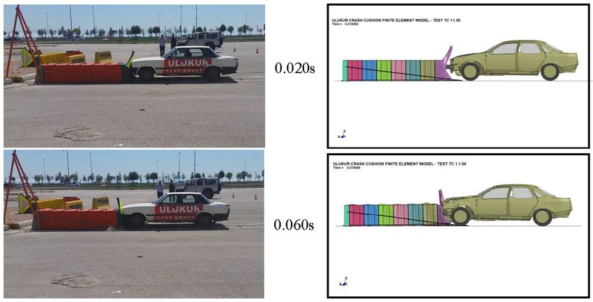
Safety 2018, 4, 48                                                                                            5 of 11

Safety 2018, 4, x FOR PEER REVIEW                                                                             5 of 11
behavior of these connections during full-scale crash testing, CONSTRAINED_SPOTWELD option
in LS-DYNA
option          was used
         in LS-DYNA       was[7]. By [7].
                               used  definition,  this option
                                          By definition,        keeps members
                                                          this option              connected
                                                                       keeps members           until auntil
                                                                                          connected    certain force
                                                                                                            a certain
criteria  is met.isThen,
force criteria      met. the   connection
                           Then,            fails and
                                   the connection      members
                                                     fails          can move
                                                           and members       canfreely.
                                                                                   moveTofreely.
                                                                                           determine   the required
                                                                                                 To determine     the
force level  that fails a connection,   a detailed model    is constructed   using  LS-DYNA.
required force level that fails a connection, a detailed model is constructed using LS-DYNA.   The  behavior   of The
                                                                                                                  the
connection
behavior ofwas the examined
                    connection  under
                                  was different
                                        examinedloading
                                                    under conditions.     A reasonable
                                                             different loading           failure
                                                                                  conditions. A criterion
                                                                                                 reasonable obtained
                                                                                                              failure
from  the component
criterion   obtained from simulation   was used
                              the component       in the connection
                                               simulation     was usedmodel
                                                                         in the[11].
                                                                                 connection model [11].

                                (a)                                                       (b)
                     Figure 4. Finite element model of UCC: (a) frontal view and
                                                                             and (b)
                                                                                 (b) rear
                                                                                     rear view.
                                                                                          view.

4.2.
4.2. Vehicle
     Vehicle Model
             Model
     After
      After the
            the development
                 development of of the
                                    the UCC
                                        UCC model,
                                             model, aa small
                                                       small passenger
                                                              passenger car
                                                                         car model
                                                                              model was
                                                                                      was used
                                                                                          used to
                                                                                                to meet
                                                                                                   meet the
                                                                                                         the EN
                                                                                                             EN
1317 standard   requirements   to  impact the barrier. A 2002  Ford  Taurus vehicle   model  obtained
1317 standard requirements to impact the barrier. A 2002 Ford Taurus vehicle model obtained from       from  the
National   Crash
the National       Analysis
                Crash        Center
                        Analysis      (NCAC)
                                   Center      was used
                                           (NCAC)    was in  the in
                                                          used   study
                                                                    the [13].
                                                                        studyThe   mass
                                                                                [13]. Theofmass
                                                                                            the empty
                                                                                                  of thevehicle
                                                                                                          empty
was  adjusted   to 900  kg, and it  could have been  increased   to 1300 kg  by  adding  extra mass
vehicle was adjusted to 900 kg, and it could have been increased to 1300 kg by adding extra mass      elements.
This particular
elements.   This vehicle   model
                   particular      was model
                              vehicle   used inwas
                                               many    previous
                                                    used  in many studies with success
                                                                      previous   studies [14].
                                                                                          withAsuccess
                                                                                                 picture[14].
                                                                                                          of the
                                                                                                               A
vehicle
picture is
         ofshown    in Figure
            the vehicle       5. in Figure 5.
                         is shown

                 Figure 5. The
                 Figure 5. The 2002
                               2002 Ford
                                    Ford Taurus
                                         Taurus vehicle
                                                vehicle model
                                                        model used
                                                              used in
                                                                    in LS-DYNA
                                                                       LS-DYNA Impact
                                                                                ImpactSimulation.
                                                                                      Simulation.
4.3. TC 1.1.50 Simulation
      After the final modifications on the vehicle model, the simulation was setup according to TC 1.1.50
      After the final modifications on the vehicle model, the simulation was setup according to TC
conditions specified in EN 1317 part 3 [6]. This head-on crash test with 900 kg vehicle is performed
1.1.50 conditions specified in EN 1317 part 3 [6]. This head-on crash test with 900 kg vehicle is
to evaluate the energy-absorption capability of the UCC design and its effectiveness at reducing the
performed to evaluate the energy-absorption capability of the UCC design and its effectiveness at
velocity of impacting vehicle in a controlled manner, thus reducing occupant injury risks. As shown
reducing the velocity of impacting vehicle in a controlled manner, thus reducing occupant injury
in Figure 6, the vehicle was positioned in front of the cushion at 0 degrees impact angle. The vehicle
risks. As shown in Figure 6, the vehicle was positioned in front of the cushion at 0 degrees impact
speed was 50 kph. In this simulation no dummy was used. Simulation was run about 0.15 s until the
angle. The vehicle speed was 50 kph. In this simulation no dummy was used. Simulation was run
vehicle’s kinetic energy completely dissipated by the crash cushion and vehicle was pushed backwards.
about 0.15 s until the vehicle’s kinetic energy completely dissipated by the crash cushion and vehicle
was pushed backwards. As shown in Figure 7, vehicle hit the barrier; instantly, the front container
began to deform and bent towards the impacting vehicle. 0.06 s after the initial impact, the kinetic
energy of the vehicle was significantly reduced and the velocity of the vehicle was approximately 28
Impact Performance Evaluation of a Crash Cushion Design Using Finite Element Simulation and Full-Scale Crash Testing - MDPI
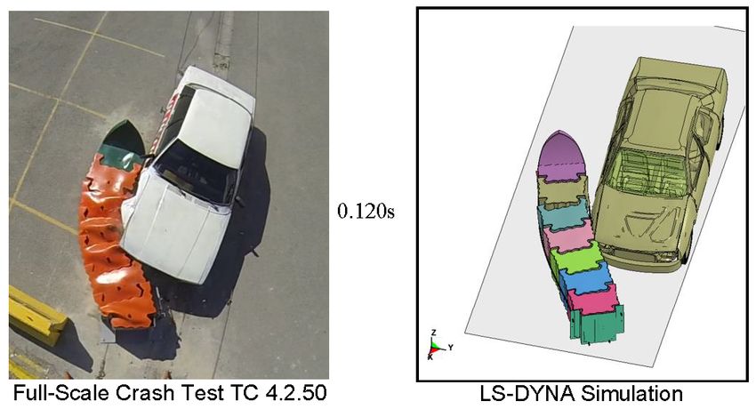
Safety 2018, 4, 48                                                                                                        6 of 11

As shown in Figure 7, vehicle hit the barrier; instantly, the front container began to deform and bent
Safety
Safety 2018,
towards      4,
             4, xx FOR
       2018,the         PEER
                        PEER REVIEW
                    impacting
                    FOR          vehicle. 0.06 s after the initial impact, the kinetic energy of the vehicle66 was
                               REVIEW                                                                                       of
                                                                                                                            of 11
                                                                                                                               11
significantly reduced and the velocity of the vehicle was approximately 28 km/h. 0.072 s after the
km/h.
km/h. 0.072
         0.072 ss after
                     after the
                           the initial
                                initial  contact,  the
                                                   the second
                                         contact,began second     container
                                                                  container   began
                                                                              began toto deform
                                                                                         deform    and absorbed      the rest  of
initial  contact,     the second     container            to deform      and absorbed    the restand     absorbed
                                                                                                    of the  kinetic the  rest of
                                                                                                                     energy    of
the  kinetic
the vehicle.     energy
      kinetic energy        of the
                            of the   vehicle.
                                     vehicle.  Thus,   0.12
                                                Thus, impact  s  after
                                                       0.12 s after     the  initial impact   with   the  UCC,     vehicle  was
the               Thus, 0.12     s after  the initial             with the   initial vehicle
                                                                        the UCC,     impact was
                                                                                              withbrought
                                                                                                     the UCC,  to avehicle  was
                                                                                                                    controlled
brought
brought      to
             to    aa controlled
                      controlled     stop.
                                     stop.  Vehicle
                                             Vehicle   left
                                                       left  the
                                                             the    UCC
                                                                    UCC    in
                                                                           in  aa stable
                                                                                  stable  and
                                                                                          and    upright
                                                                                                 upright   position.
                                                                                                            position.   Energy
                                                                                                                        Energy
stop. Vehicle left the UCC in a stable and upright position. Energy absorption performance of the UCC
absorption
absorption       performance
                 performance       of
                                   of the
                                      the UCC
                                           UCC    was acceptable,      which   resulted  in low
                                                                                            low occupant      risk values   that
was   acceptable,      which resulted      in lowwas   acceptable,
                                                    occupant           which that
                                                                 risk values   resulted
                                                                                     wereinmeasured
                                                                                                  occupant
                                                                                                        insiderisk
                                                                                                                 thevalues  that
                                                                                                                     vehicle.  A
were
were    measured
        measured        inside
                        inside   the
                                 the  vehicle.
                                      vehicle.   A
                                                 A  picture
                                                    picture   of
                                                              of   the
                                                                   the deformed
                                                                       deformed      shape
                                                                                     shape  of
                                                                                            of  the
                                                                                                the  barrier
                                                                                                     barrier   after
                                                                                                               after  TC
                                                                                                                      TC  1.1.50
                                                                                                                          1.1.50
picture of the deformed shape of the barrier after TC 1.1.50 simulation is shown in Figure 8. Based on
simulation
simulation       is
                 is shown
                     shown    in
                              in Figure
                                  Figure   8.
                                           8. Based
                                              Based   on
                                                      on the    simulation
                                                          thethat
                                                                simulation    predictions,
                                                                              predictions,   it
                                                                                             it was   determined
                                                                                                wascontained
                                                                                                      determined      that UCC
the  simulation       predictions,     it was  determined            UCC design      successfully                 andthat  UCC
                                                                                                                       stopped
design
design    successfully
          successfully      contained     and
                            containedinjury    stopped
                                          and stopped     900   kg  vehicle   with  minimal   injury  risk  to
                                                          900 kg vehicle with minimal injury risk to occupants. occupants.
900  kg vehicle       with minimal              risk to occupants.

                                          Full-Scale
                                          Full-Scale Crash
                                                     Crash Test
                                                           Test TC
                                                                TC 1.1.50
                                                                   1.1.50

                                                  LS-DYNA
                                                  LS-DYNA Simulation
                                                          Simulation
                     Figure
                     Figure 6.
                            6. The
                               The 900
                                   900 kg
                                       kg car
                                          car positioned
                                              positioned in
                                                         in front of UCC
                                                            front of UCC barrier
                                                                         barrier before
                                                                                 before TC
                                                                                        TC 1.1.50.
                                                                                           1.1.50.
                                                                                           1.1.50.

                                                       Figure 7. Cont.
Impact Performance Evaluation of a Crash Cushion Design Using Finite Element Simulation and Full-Scale Crash Testing - MDPI
Safety 2018, 4, 48                                                                                         7 of 11
   Safety
Safety    2018,
       2018, 4, x4,FOR
                    x FOR PEER
                       PEER    REVIEW
                            REVIEW                                                                         7 of711
                                                                                                                 of 11

              Figure
           Figure
           Figure 7. 7. Sequential
                  7. Sequential
                     Sequential    picture
                                picture
                                picture    comparison
                                        comparison
                                        comparison of of
                                                   of UCC
                                                      UCCUCC  after
                                                           after
                                                           after TCTC
                                                                 TC    1.1.50
                                                                    1.1.50
                                                                    1.1.50    crash
                                                                           crash
                                                                           crash testtest
                                                                                      andand simulation.
                                                                                          simulation.

            Figure 8. Deformed
               Figure           shape
                      8. Deformed     comparison
                                  shape          of of
                                        comparison  UCC  after
                                                       UCC     TC 1.1.50
                                                            after        crash test and simulation.
            Figure 8. Deformed shape  comparison of UCC  after TCTC  1.1.50
                                                                  1.1.50    crash
                                                                         crash testtest
                                                                                    andand simulation.
                                                                                        simulation.
Impact Performance Evaluation of a Crash Cushion Design Using Finite Element Simulation and Full-Scale Crash Testing - MDPI
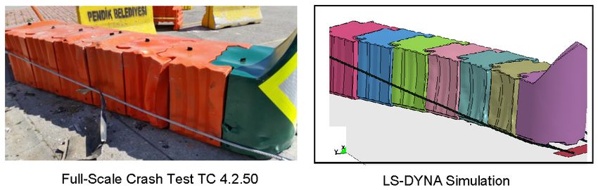
Safety 2018, 4, 48                                                                                                             8 of 11
Safety
Safety 2018,
       2018, 4,
             4, xx FOR
                   FOR PEER
                       PEER REVIEW
                            REVIEW                                                                                             88 of
                                                                                                                                  of 11
                                                                                                                                     11

4.4. TC 4.2.50 Simulation
      A second
         secondsimulation
                    simulationstudystudywas was    also
                                                also      performed
                                                      performed          to evaluate
                                                                     to evaluate         side impact
                                                                                   side impact            capacity
                                                                                                   capacity   of the UCCof thedesign.
                                                                                                                                UCC
design.
As        As described
    described    by test TC by4.2.50,
                                test TC    4.2.50,
                                       a 1300     kg acar
                                                        1300   kg car
                                                           model    wasmodel     was positioned
                                                                         positioned                   so that
                                                                                        so that it would         it would
                                                                                                             impact           impact
                                                                                                                        the cushion
the  cushion    1/3rd   of the  length   (see    Figure    9). The   vehicle  contacted      the  barrier
1/3rd of the length (see Figure 9). The vehicle contacted the barrier at 15 degrees angle, and the velocityat   15  degrees    angle,
and
of thethe  velocity
        vehicle   justofbefore
                          the vehicle
                                the impactjust was
                                                 before50 the
                                                           kph.impact     was the
                                                                  Following    50 kph.
                                                                                     initialFollowing
                                                                                              contact, asthe    initialincontact,
                                                                                                            shown         Figure 10,as
shown
first andinsecond
            Figurecontainers
                      10, first and   second
                                    began        containers
                                             to deform           beganthus
                                                            laterally,   to deform
                                                                             absorbing laterally,  thus absorbing
                                                                                            the impact    energy of the  the vehicle.
                                                                                                                              impact
energy
As        of the vehicle.
    the vehicle    continued As totheslide
                                       vehicle     continued
                                              on the              to slide
                                                        side of the     UCC,onit the  side ofmore
                                                                                 contacted       the UCC,      it contacted
                                                                                                       containers               more
                                                                                                                        and vehicle
containers    and vehicle
speed was further              speed
                        reduced.        wass after
                                    At 0.1      furtherthereduced.      At 0.1
                                                            initial impact,  thes first
                                                                                   afterfour
                                                                                           the containers
                                                                                                initial impact,      the moderate
                                                                                                              received     first four
containers
damage and     received
                 vehicle’s moderate
                              velocity damage
                                          was almost   and28vehicle’s
                                                                kph. Asvelocity
                                                                            shown in   was    almost 28
                                                                                          sequential        kph. As
                                                                                                         pictures         shown 10,
                                                                                                                      in Figure     in
sequential   pictures    in Figure    10,  0.2 s  after  the  initial  impact,  cushion     was   able
0.2 s after the initial impact, cushion was able to contain and redirect impacting vehicle without any  to contain     and   redirect
impacting
breakage ofvehicle       withoutDamage
                the elements.        any breakage
                                               to the UCC of theandelements.    Damage
                                                                      vehicle were            to theThe
                                                                                       moderate.      UCC      and vehicle
                                                                                                           vehicle               were
                                                                                                                      left the UCC
moderate.    The   vehicle   left  the UCC      in a  stable   and   upright  position.     Energy
in a stable and upright position. Energy absorption performance of the UCC was acceptable, which      absorption      performance
of the UCC
resulted       wasoccupant
           in low    acceptable, riskwhich
                                      valuesresulted
                                                 measured  in low   occupant
                                                               inside           risk values
                                                                        the vehicle.            measured
                                                                                        A picture             inside theshape
                                                                                                     of the deformed         vehicle.
                                                                                                                                    of
A
thepicture
     barrierof   theTC
              after    deformed      shape of the
                          4.2.50 simulation              barrierinafter
                                                   is shown         FigureTC11.
                                                                              4.2.50
                                                                                  Based simulation     is shownpredictions,
                                                                                          on the simulation          in Figure 11.   it
Based   on  the  simulation     predictions,      it was    determined     that  UCC     design    has
was determined that UCC design has the potential to satisfy 50 kph test requirements described at EN    the  potential     to  satisfy
50 kph
1317     test
      part  3. requirements described at EN 1317 part 3.

                    Figure
                    Figure 9.
                           9. The
                              The 1300
                                  1300 kg
                                       kg car
                                          car positioned
                                              positioned in
                                                         in front
                                                            front of
                                                                  of UCC
                                                                     UCC barrier before TC
                                                                         barrier before TC 4.2.50.
                                                                                           4.2.50.

                                                         Figure 10. Cont.
Impact Performance Evaluation of a Crash Cushion Design Using Finite Element Simulation and Full-Scale Crash Testing - MDPI
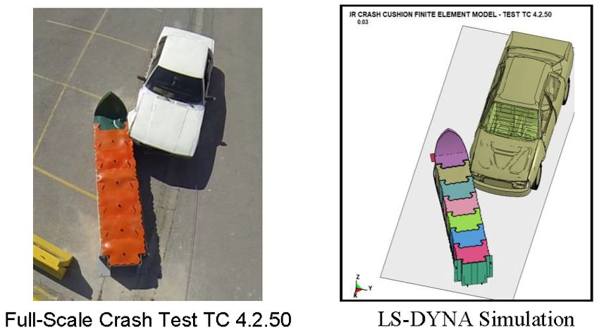
Safety 2018, 4, 48                                                                                                            9 of 11
Safety 2018, 4, x FOR PEER REVIEW                                                                                             9 of 11

           Figure 10. Sequential pictures comparison of UCC after TC 4.2.50 crash test and simulation.
                      Sequential pictures
           Figure 10. Sequential
           Figure                pictures comparison
                                          comparison of UCC after TC 4.2.50 crash test and simulation.

             Figure 11. Deformed shape comparison of UCC after TC 4.2.50 crash test and simulation.
             Figure 11. Deformed shape comparison of UCC after TC 4.2.50 crash test and simulation.
             Figure 11. Deformed shape comparison of UCC after TC 4.2.50 crash test and simulation.
5. Full-Scale Crash Testing
     After performing
5. Full-Scale            two successful simulation studies for tests TC 1.1.50 and TC 4.2.50, same tests
              Crash Testing
were performed using two
      After performing         successful
                          full scale crashsimulation  studies
                                           cushion. Crash      forwere
                                                            tests  testsrun
                                                                         TC 1.1.50 and TC
                                                                            in Istanbul   4.2.50,
                                                                                        during thesame tests
                                                                                                    summer
     After performing two successful simulation studies for tests TC 1.1.50 and TC 4.2.50, same tests
were
of    performed
   2016.           using
         These tests  werefull scale crash
                            intended       cushion.
                                       to both verifyCrash  tests werefindings
                                                      the simulation    run in Istanbul during theprove
                                                                                 and conclusively   summer
                                                                                                        the
were performed using full scale crash cushion. Crash tests were run in Istanbul during the summer
of 2016. Theseoftests
acceptability     UCCwere   intended
                        design         to both
                                for 50 kph     verify the simulation findings and conclusively prove the
                                            conditions.
of 2016. These tests were intended to both verify the simulation findings and conclusively prove the
acceptability of UCC design for 50 kph conditions.
acceptability
5.1. Crash TestofTC
                  UCC   design for 50 kph conditions.
                    1.1.50
5.1. Crash    Test TC
       As shown         1.1.50 6 and 7, a full-scale crash test was performed on UCC design according to
                     in 1.1.50
                        Figures
5.1. Crash   Test TC
EN 1317     part 3 TC
       As shown          1.1.50 conditions
                     in Figures    6 and 7, a[9].     The UCC
                                                  full-scale  crashdesign    wasperformed
                                                                       test was    installed ononconcrete      pavement
                                                                                                      UCC design            and the
                                                                                                                      according    to
impactAs   shown     in Figures    6  and   7, a  full-scale  crash   test  was   performed      on   UCC    design  according     to
EN 1317point,
            part 3asTC described     in EN 1317
                         1.1.50 conditions       [9].part
                                                      The3,   wasdesign
                                                            UCC     a 1991wasmodel     Ford Taurus,
                                                                                   installed   on concretewhich   used as and
                                                                                                               pavement     the test
                                                                                                                                  the
EN   1317 The
vehicle.    parttotal
                  3 TCmass
                         1.1.50ofconditions
                                   the   tested  [9]. The UCC 900
                                                   vehicle         design   was installed      on concrete  kg pavement     and the
impact point,      as described      in EN    1317   part 3,was
                                                              was a 1991 kg when
                                                                              model  empty
                                                                                       Ford and
                                                                                              Taurus,1300which with
                                                                                                                  usedtheasaddition
                                                                                                                             the test
impact
of dummy  point,  as  described     in   EN   1317   part 3, was    a  1991  model     Ford   Taurus,     which   used   as the test
vehicle.   Theandtotalmeasurement
                        mass of the testeddevices.    The was
                                                 vehicle    vehicle
                                                                 900 positioned
                                                                       kg when empty  in the  test1300
                                                                                             and     track
                                                                                                         kgaccelerated     towards
                                                                                                             with the addition     of
vehicle.
the        The total
     test article  at anmass   of the
                           angle        tested
                                   ofdevices.
                                       zero      vehicle
                                              degrees     was a900
                                                        using         kg when
                                                                   cable   pullyinempty
                                                                                   mechanismand 1300     kg  with the
                                                                                                   andaccelerated
                                                                                                         impacted    theaddition   of
                                                                                                                          barrierthe
                                                                                                                                   at
dummy       and measurement                       The vehicle     positioned         the test track                    towards
dummy
51.5  kph.and     measurement
             Behavior     of the     devices.
                                           and The     vehicleare positioned     in the   test track   accelerated    towards    the
test article   at an angle     of UCC
                                   zero degrees   the using
                                                      vehicle a cable illustrated   in Figure
                                                                          pully mechanism         7. As
                                                                                                  and     expected,the
                                                                                                        impacted       vehicle  was
                                                                                                                          barrier   at
test
not   article  at an   angle   of  zero    degrees    using   a  cable   pully   mechanism        and   impacted    the  barrier   at
51.5able
       kph.toBehavior
               damage of   thethe
                                cushion
                                   UCC and  significantly.
                                                  the vehicle Only     the first and
                                                                 are illustrated     insecond
                                                                                         Figure containers      compressed
                                                                                                   7. As expected,     vehicle and
                                                                                                                                 was
51.5  kph. Behavior
absorbed                  ofenergy
                             the UCC       andvehicle.
                                                 the vehicle     are  illustrated   in Figurein7.an   Asacceptable
                                                                                                          expected, manner
                                                                                                                       vehicle was
not able tothe    kinetic
                damage     the cushion of thesignificantly. The   vehicle
                                                               Only         slowed
                                                                       the first  anddown
                                                                                        second containers       compressed and   and
not
came able
        to ato damage
              stop.   Data the  cushion
                            collected       significantly.
                                          from    the         Only
                                                      accelerometer,  the  first
                                                                           which  and
                                                                                    was second    containers
                                                                                          installed    at the   compressed
                                                                                                              vehicle’s         and
                                                                                                                           center  of
absorbed the kinetic energy of the vehicle. The vehicle slowed down in an acceptable manner and
absorbed
gravity,     the  kinetic   energy     of  the  vehicle.   The    vehicle   slowed     down     in  an  acceptable    manner    and
came towere       used
            a stop.      to calculate
                      Data  collectedthe  fromoccupant    injury risks. which
                                                  the accelerometer,       Due towas the softened
                                                                                           installednose
                                                                                                       at thedesign  of the
                                                                                                               vehicle’s      barrier
                                                                                                                           center  of
came
and     to aspeed
      low     stop. of
                     Data   collected
                        vehicle   occupantfrom injury
                                                 the accelerometer,
                                                         risk,  the  valueswhich
                                                                              were  was   installed at
                                                                                      determined       to the
                                                                                                           be vehicle’s center
                                                                                                              negligible.   Resultsof
gravity, were used to calculate the occupant injury risks. Due to the softened nose design of the
gravity,
of TC 1.1.50werecrash
                   usedtestto calculatethat the theoccupant    injuryisrisks.    Due to to  thecontain
                                                                                                 softened andnose   design    of the
barrier   and low     speed showed
                               of vehicle occupant    UCC    design
                                                           injury   risk, soft enough
                                                                           the values     were   determined    stop  annegligible.
                                                                                                                 to be    impacted
barrier
vehicle   andanlow    speed ofmanner.
                                  vehicle occupant injury risk, the values were determined to be negligible.
Results in of TCacceptable
                    1.1.50 crash     test showed that the UCC design is soft enough to contain and stop an
Results of TC 1.1.50 crash test showed that the UCC design is soft enough to contain and stop an
impacted vehicle in an acceptable manner.
Impact Performance Evaluation of a Crash Cushion Design Using Finite Element Simulation and Full-Scale Crash Testing - MDPI
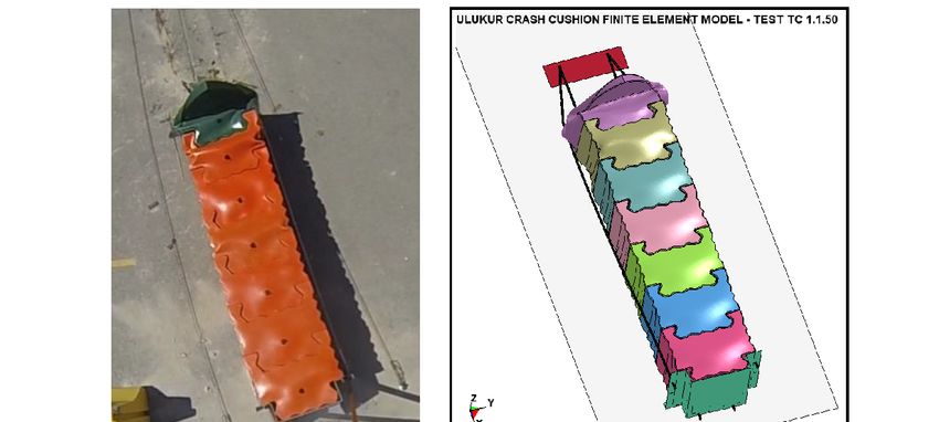
Safety 2018, 4, 48                                                                                          10 of 11

5.2. Crash Test TC 4.2.50
      After repairing damaged containers and rotating the cushion 15 degrees, a second crash test
was performed on UCC design according to EN 1317 part 3 test TC 4.2.50 conditions [10]. As shown
in Figure 9, a 1320 kg Ford Taurus impacted the barrier with a speed of 51 kph and at an angle of
15 degrees. The impact point was 1.5 m away from the nose, which is equal to one third of the distance
of the UCC. Following the initial contact, as shown in Figure 10, first two containers that received the
impact force began to deform and absorb the initial impact loads. As the vehicle continued to slide on
the side of the UCC, as in the simulation study, it contacted barriers number three and four, which
reduced the vehicle speed a further 0.1 s; after the initial impact, the first four containers received
moderate damage and the vehicle’s velocity was almost 32 kph. As shown in sequential pictures in
Figure 10, 0.22 s after the initial impact, cushion was able to contain and redirect the impacting vehicle
in an acceptable manner. Damage to the UCC and vehicle were moderate. The vehicle left the UCC
in a stable and upright position. Energy absorption performance of the UCC was acceptable, which
resulted in low occupant risk values measured inside the vehicle. A picture of the deformed shape
of the barrier after TC 4.2.50 crash test is shown in Figure 11. As predicted by LS-DYNA simulation
study, UCC design successfully passed the 50 kph test requirements described in EN 1317 part 3 [6].

6. Summary and Conclusions
     This paper deals with designing, analyzing, and testing a new, reusable, low-cost, and simple
crash cushion, UCC, for roads with 50 kph speed limits. UCC design included LLDPE containers
with embedded LLDPE energy-absorbing tubes as dampers. The design was strengthened by steel
cables and steel plates. The crashworthiness of the system was evaluated both numerically and
experimentally. Finite element analysis of the UCC design showed that the design is flexible enough to
contain, and successfully stop, a 900 kg car impacting head-on and rigid enough to successfully redirect
the 15 degree side impact of a 1300 kg vehicle at one third of the location of the design. Following the
promising simulation study, the design was installed at a test facility and two full scale crash tests
were performed on UCC to conclusively determine its performance under 50 kph vehicle impacts.
Both simulation and crash test results agreed well, proving the crashworthiness and acceptability of
the design at 50 kph. Damage to UCC was moderate, and the occupant risk factors were below injury
threshold. Since UCC design is composed of modular elements, the design could be easily repaired
and put back to service. Finally, performing further crash tests at higher speeds, such as 80, 100, and
110 kph, is recommended to fully assess the acceptability of the new crash cushion system developed.

Author Contributions: A.O.A. and M.B. carried out the finite element simulations performed full-scale crash
tests and constructed the manuscript. K.K. provided the crash cushion design, materials and prepared the setup
to perform full-scale crash tests.
Funding: This research received no external funding.
Conflicts of Interest: The authors declare no conflict of interest.

References
1.    Istanbul Metropolitan Municipality (IMM). Istanbul Traffic Safety Strategic Plan; Technical Report IBB-3-TS04;
      Istanbul Metropolitan Municipality: Istanbul, Turkey, 2016.
2.    TRA. Traffic Safety Handbook; Turkish Road Association, Department of Transportation: Ankara, Turkey, 2011.
3.    American Association of State Highways and Transportation Officials (AASHTO). Roadside Design Guide,
      4th ed.; American Association of State Highways and Transportation Officials: Washington, DC, USA, 2011.
4.    FHWA. Online Guide to Crash Cushions. Federal Highway Administration, U.S. Department of
      Transportation, Washington, DC, USA, 2013. Available online: https://safety.fhwa.dot.gov/roadwaydept/
      countermeasure/docs/CrashCushionsNov2013Safelogo.pdf/ (accessed on 6 March 2018).
5.    TUİK. Vehicle data on Turkish Highways; Turkish Statistics Organization: Ankara, Turkey, 2016.
Safety 2018, 4, 48                                                                                        11 of 11

6.    CEN. European Committee for Standardization. European Standard EN1317, Road Restraint Systems—Part 3:
      Performance Classes, Impact Test Acceptance Criteria and Test Methods for Crash Cushions; Committee European
      de Normalization (CEN): Brussels, Belgium, 2010.
7.    Livermore Software Technology Corporation (LSTC). LS-DYNA Keyword User’s Manual; Livermore Software
      Technology Corporation: Livermore, CA, USA, 2017.
8.    Cozzi, A.C.; Briasco, B.; Salvarani, E.; Mannucci, B.; Fangarezzi, F.; Perugini, P. Evaluation of Mechanical
      Properties and Volatile Organic Extractable to Investigate LLDPE and LDPE Polymers on Final Packaging
      for Semisolid Formulation. Pharmaceutics 2018, 10, 113. [CrossRef] [PubMed]
9.    Ulukur. TC 1.1.50 Crash Tests on UCC Crash Cushion; Test No. 001/ITU/17; Crash Test Facility: Istanbul,
      Turkey, 2017.
10.   Ulukur. TC 4.2.50 Crash Tests on UCC Crash Cushion; Test No. 002/ITU/17; Crash Test Facility: Istanbul,
      Turkey, 2017.
11.   Atahan, A.O.; Bonin, G. Numerical analysis of an H4a heavy containment level transition. Int. J. Heavy Veh.
      Syst. 2006, 13, 351–365. [CrossRef]
12.   Vesenjak, M.; Borovinsek, M.; Ren, Z. Computational and experimental crash analysis of the road safety.
      Eng. Fail. Anal. 2005, 12, 963–973.
13.   FEMA. Finite Element Model Archive, FHWA/NHTSA National Crash Analysis Center, Virginia, 2002.
      Available online: http://www.ncac.gwu.edu/vml/models.html (accessed on 6 March 2018).
14.   Atahan, A.O. Vehicle crash test simulation of roadside hardware using LS-DYNA: A literature review. Int. J.
      Heavy Veh. Syst. 2009, 17, 52–75. [CrossRef]

                       © 2018 by the authors. Licensee MDPI, Basel, Switzerland. This article is an open access
                       article distributed under the terms and conditions of the Creative Commons Attribution
                       (CC BY) license (http://creativecommons.org/licenses/by/4.0/).
You can also read