Impact Factor: 7.569 Volume 10, Issue 7, July 2021 - IJIRSET
←
→
Page content transcription
If your browser does not render page correctly, please read the page content below

Volume 10, Issue 7, July 2021

Impact Factor: 7.569

International Journal of Innovative Research in Science, Engineering and Technology (IJIRSET)

                       | e-ISSN: 2319-8753, p-ISSN: 2320-6710| www.ijirset.com | Impact Factor: 7.569|

                                        || Volume 10, Issue 7, July 2021 ||
                                         |DOI:10.15680/IJIRSET.2021.1007101|

      Methodology of Designing and Failure
    Analysis of Concrete mixer Machine Blades
                                 Shubham B. Babhale *1, Dr. R. R. Gawande *2
           PG-Student, Department of Mechanical Engineering, Bapurao Deshmukh College of Engineering,
                                      Sewagram, Wardha, Maharashtra, India. *1
            Professor , Department of Mechanical Engineering, Bapurao Deshmukh College of Engineering,
                                      Sewagram, Wardha, Maharashtra, India. *2

ABSTRACT:Wainganga spun pipe industries pvt. Ltd , Sewagram used special types of Concrete mixer machine for
making concrete mixture required for making RCC spun pipe . In this machine ,there is horizontal shaft on which 4
blade assembly bolted which mixes the concrete mixer. all concrete mixtures homogeneously mix by rotating blade on
shaft of mixer machine. In this project Design and Analysis of blades of concrete mixer machine has done. The main
objective of this analysis is to optimize the design of blades of concrete mixer machine . mixer blades directly affect
the mixing performance. Good mixing performance obtain by designing the mixing arm and mixing blade Mixing
blades force the Concrete material along the circumference for mixing, and also along the shaft for transport during the
mixing process While mixing concrete material, machine blades does not mix mixture uniformly and pull all material
on one side cause high stresses induced in blade & blade get breaks. Also low quality concrete mixture reduce the
efficiency of concrete mixer machine. Present design of blades is not strong enough to bear stresses & not satisfactory
for making mixture. so this study is made for Design And Failure Analysis Of Blades of concrete mixer to make it
effective. Study done on existing concrete machine blades & with the help of existing blades, modified blades
design.by making this study blades work more effectively, uniformly mixes all material & increases efficiency of
machine. The analytical results which are done on FEM ansys also show that existing model of blade has high value
for deformation, max shear stress and von mises stress.so the deformation , maximum shear stress and von mises shear
stress reduced in modified blade assembly design shown by FEM ansys.

KEYWORDS: Horizontal shaft concrete mixer machine, Modification of blade , failure analysis on blade of
concrete mixer , T shape blade of concrete mixer.

                                                I. INTRODUCTION

Concrete mixer machine is utilized for mixing cement, sand, gravel and water uniformly. in Wainganga spun pipe
industries pvt. Ltd , Sewagram road ,MIDC Wardha. In concrete mixer machine rotating blades mix concrete material
uniformly. In Wainganga Spun Pipe Industry, it has been observed that the blades of mixer not mix concrete mixture
uniformly also blade ger break . While working of machine ,concrete mixture between blades remains unmixed.
Existing blade design push all concrete material unevenly causes high stresses on one blade & blade get break. So in
this project research is done to identify the causes of blade failure & modified design of existing blade which is
capable to withstand heavy stresses.
      In this project I studied the existing concrete machine at Wainganga industry and takes measurement of blade
assembly & parameters required for design . then I studied various literatures papers on designs of concrete
machine ,shapes of blades, material of blades & working of machine and reasons behind the failure of blade. then
created the CAD model of blade assembly with existing material and properties . analyse it using ANSYS software for
deformation value, maximum shear stress value and von misses shear stress & then this value reduced in modified
blade assembly .

IJIRSET © 2021                                   |   An ISO 9001:2008 Certified Journal |                         9326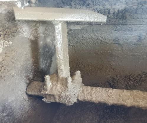
International Journal of Innovative Research in Science, Engineering and Technology (IJIRSET)

                        | e-ISSN: 2319-8753, p-ISSN: 2320-6710| www.ijirset.com | Impact Factor: 7.569|

                                         || Volume 10, Issue 7, July 2021 ||
                                         |DOI:10.15680/IJIRSET.2021.1007101|

                                                     II. RELATED WORK

a)Number of Blades on shaft
  Konstantin (2020)It states that impact of the number and tallness of sharp edges of a substantial blender on the
combination quality. point of this investigation was to develop the effect of the number and stature of forefronts of a
drum blender on the idea of the set up mix of concentrated feed. The execution of the used investigation reasoning for
the action of the drum blender made it possible to develop an adequate helpful dependence of the effect of the amount
of edges and their height on the idea of the mix. The amount of sharp edges used essentially doesn't impact the
coefficient of assortment of the substance of the control part. Methods and Materials obliged the foundation of
replaceable working bodies (L-shaped edges) on the inside surface of the turning drum of the blender, changing in
number and height; confirmation of the idea of the coordinated mix and quantifiable examination of the results (2).
  Wankhede (2016) It expresses that The property of edge and shaft improved either by changing material or by
changing its measurement . Shaft is a huge stuff of considerable blender machine use for significant mix arranging and
for help a turning drum. The essential objective of this assessment is to upgrade the arrangement of generous blender
machine. To research this shaft using FEM, as a matter of first importance a suitable CAD model is made using Pro/E
lowlife programming. By then by using ANSYs programming FEM assessment is done to choose the different sorts of
stresses and redirection made. After did the examination it has been found that the current arrangement of shaft of
significant blender machine isn't suitable and therefor I had proposed to change the material of the shaft for capable
working and to withstand the unmistakable static and dynamic weight (10).

b)Fixing Angle Of Blade
Zechen YAO (2019 ) investigates that the blender sharp edges load increments with the cutting edge setting point.
Additionally blending arm is exposed to the consolidated impact of ductile and twisting anxieties. at the point when
point between the blending arm and the blending shaft is θ=90 º, the pressure arrives at its most extreme . The
inspiration driving this paper is to improve the numerical limits of the mixing paddle of CSAM blender from the
mechanical assessment viewpoint. In this paper, the improvement of a mixing arm and sharp edge's numerical limits
was finished ward on mechanical assessment using the Matlab programming group and FEA. It offers speculative
assistance for the arrangement and smoothing out of mixing paddles for CSAM blenders. It justifies raising that the
examination procedure depicted here can be applied to the arrangement of mixing paddle of blender for various
organizations. The assessment results are summarized: A mixing edge's stack FN'is influenced by such factors as the
material thickness ρ, mixing edge area A, mixing rotational speed ω, distance between mixing bleeding edge and center
r, and the mixing edge point setting α. The FN'on a mixing sharp edge increases with the state of the art setting point
(3).

Zhang (2020)explore that The more modest the cutting edge establishment point, the more uniformly the pressing
factor dissemination on edge. This examination can give a reference to the arrangement choice of the foundation point
of the mixing bleeding edge of significant blenders. The surface squeezing factor spreads of the mixing part under the
fve edgefoundation focuses were gotten. The best squeezing factor is scattered at the most elevated mark of the
squeezing factor surface of the mixing edge. The theoretical most outrageous line wear speed of the edges for the five
state of the art foundation focuses was inspected, and the speculative life at fve focuses was controlled by the
contrasting change on the establishments of the scratched spot arrangement of the blender and unpleasant wear formula.
Also, the best foundation point and its span were settled (4).

c)Cross-sectional Shape of Blade

   Khidir(2018)studied that Centrifugal Blades is best from the Other ones for adequacy . This paper deals with the
arrangement and examination of an edge for substantial blender in motivation to find a safe arranged removable
bleeding edge for multi utilize substantial blender. It's a guideline part of a blender which helps mixing the components
of the substantial for better quality concrete. For side bleeding edges type the sharp edges turns with drum
notwithstanding in Centrifugal Blades Type the edges turns clearly. We use the edges a couple of times to find the best
edge shape for better mixing, least disillusionment, easier to supersede and more affordable in esteem consequently
avoiding change in the whole drum when the edge crashes and burns (5).

 Valigi(2019)Studied that the blender with complete system power with the T sharp edges is 3.8% above than the case
with the L shape which grant energy saving and upgraded creation rates. In this paper, the mechanical direct of

IJIRSET © 2021                                   |    An ISO 9001:2008 Certified Journal |                         9327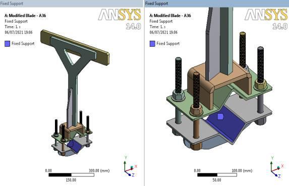
International Journal of Innovative Research in Science, Engineering and Technology (IJIRSET)

                        | e-ISSN: 2319-8753, p-ISSN: 2320-6710| www.ijirset.com | Impact Factor: 7.569|

                                         || Volume 10, Issue 7, July 2021 ||
                                          |DOI:10.15680/IJIRSET.2021.1007101|

generous twin-shaft blenders is destitute down similarly as power usage and exchanged forces between the mix and the
mixing organs during the mixing cycle. The mixing cycle is isolated into two huge scope stages, named transient and
framework stage, where the direct of the blend is exhibited in two unmistakable habits. A force appraisal and power use
assumption model are presented for both the considered stages and they are supported by test campaigns. From the
utilization of this model to different machines and by changing assorted arrangement limits, the smoothing out of the
power use of the significant twin-shaft blenders is analyzed. Eventual outcomes of this work can be used to extend
effectiveness and advantage of generous blenders and lessen energy waste in the endeavors which incorporate mixing
measures (6).

  Maria(2016) investigates that further developed calculation of blending edges for planetary substantial blenders
permitted lower wear rates and longer sturdiness. Wear of machine fragments is one of the principal wonders to control
and limit to work on the show and lessen the creation costs. In this paper, the upgrade of a planetary considerable
blender to the extent wear impediment of sharp edges is proposed and another arrangement of the mixing forefronts'
shape is showed up and analyzed. Test tests performed with two stars planetary significant blenders are portrayed and
achieved preliminary outcomes are showed up. Those results show the progression of sharp edges' wear as time goes on
and exhibit that the proposed changed edge's computation further develops the wear resistance and widens the
important life (7).

d) Material used for making Blade

 Samual(2018) considered that the by choosing hardened steel material as the sharp edge material, there is increment of
solidarity, erosion. Concrete is used comprehensively for advancement reason. Considering the utilization of concrete,
robotization of the cooperation is expected to grow creation yield. This investigation work is based on the arrangement
of an insignificant cost significant blender machine. The machine was viably planned. The efficiency of a blender is
directed by the consistency of the generous made. It could similarly be considered as being directed by the power used
in conveying a given measure of concrete of the important consistency. Others limits like force, and power was
reasonable enough that the outcome conveyed a negligible cost machine(8).

 Torotwa(2018) investigates that the impeller edge design influence the presentation of a blender. Plan and movement
of mixing structures using instigated vessels is a problematic endeavor due to the trial of securing exact information on
impeller-provoked roughness. The usage of CFD can give point by point cognizance of such structures. In this
assessment, test tests and computational fluid components multiplications were performed to take a gander at the
stream characteristics of four impeller plans (anchor, saw-tooth, counter-stream and Rushton turbine), in achieving
course of action homogeneity. It was gathered that, through CFD examination, separated information can be gotten for
ideal arrangement of mixing contraption. These disclosures are significant in picking the best mixing equipment and
gives a reason to expanding mixing errands in greater structures (9).

                                                III. METHODOLOGY
3.1. Identification Of Problem
Problem identified in concrete mixer machine related to Failure of blade at Wainganga Spun Pipe Industry,
Sewagram. For pipe making its important that the concrete mixer should be effectively working In Wainganga
Spun Pipe Industry. but it has been observed that the blades of mixer not mix concrete mixture uniformly. Also
present design of blade is not effective & stronger.It is observed that the blade of mixer machine break due to
overloading of input mixture only at one side and various forces acts on it. This results into low quality of
concrete mixture. So in this project I am researches to identify the different causes of blade failure & design such
blade which is effective & strong.

3.2. Data Accumulation
   Design data related to dimensions and process of concrete mixer machine gathered from Wainganga Spun Pipe
Industry, Sewagram.Study The Present Design Of Blades & Machine .Takes information about concrete mixture
machine machine working, background information about machine, electric motor specification, amount of
concrete material fed into concrete mixer machine from production in charge.Take dimensions of various part of
concrete mixer machine like blade assembly, gear & pinion teeth measurement , mixing tank measurement, shaft
measurement, with the help of measuring tape . Then Draft 2D diagram of concrete mixture machine. Blade

IJIRSET © 2021                                   |   An ISO 9001:2008 Certified Journal |                              9328
International Journal of Innovative Research in Science, Engineering and Technology (IJIRSET)
| e-ISSN: 2319-8753, p-ISSN: 2320-6710| www.ijirset.com | Impact Factor: 7.569|
|| Volume 10, Issue 7, July 2021 ||
|DOI:10.15680/IJIRSET.2021.1007101|
assembly is total combination of blade, arm, blade mounting plate (upper plate , bottom plate with stiffener) &
fixing bolts.
There are 4 blade assemblies (T section) mounted on square shaft as shown in pictures. Blade is made up
of Mild Steel material(A36 Grade)
Blade assembly fixed at 85 degree with respect to axis of shaft.
The peripheral speed of the paddles is approximately 167 RPM.
Cross-sectional area of blade assembly=75530 mm2 or 0.075530 m2
Figure 1 :- Blade Assembly in concrete mixer machine
3.3. Literature Survey
A detailed literature study about design of concrete mixer blade , concrete mixer machine is carried out from
research paper shown in literature review section.
3.4. Design Calculations Of Concrete Mixer Blade Assembly
Design of blade of mixer to modify the existing blade assembly by performing design calculations.Then after
finding reasons behind the breaking of blade from various research papers and books I collected data about shear
stress analysis and shear capacity strength of blade for calculations. I followed many research papers, books and
design data book for material properties of blade to solve calculations.
i)calculation of forces on blade assembly
The loads exerted on the blade include:
1) centrifugal force Fc
2)pressure FN
3)frictional FF
4)gravity G
5)mass of concrete on 1 blade F CM
Combining all force we get total force.
ii) Calculation Of Stress On Blade Assembly
Axial tensile load on blade (σt )=total load/ cross sectional area
Also shear force calculated.
iii) calculation of maximum shear stress & equivalent shear stress by von mises stress (according to distortion energy
theory)on existing blade
by calculating maximum shear stress & Von mises stress, we know that all forces acts on blade is above the allowable
stresses of blade. So blade break.
IJIRSET © 2021 | An ISO 9001:2008 Certified Journal | 9329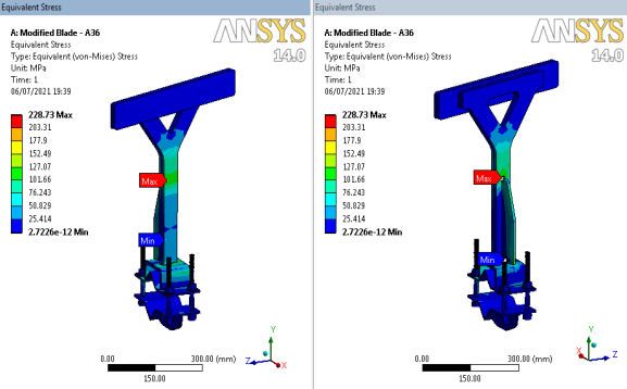
International Journal of Innovative Research in Science, Engineering and Technology (IJIRSET)

                       | e-ISSN: 2319-8753, p-ISSN: 2320-6710| www.ijirset.com | Impact Factor: 7.569|

                                        || Volume 10, Issue 7, July 2021 ||
                                         |DOI:10.15680/IJIRSET.2021.1007101|

3.5. CAD Modeling Of Design
 Develop CAD model of modified machine by using CAD software. The designing of existing blade on the
AutoCAD cad model and designing of Modified blade done.
i) Existing Design Of Blade
There are 4 blade assemblies (T section) mounted on square shaft as shown in pictures.
Blade is made up of Mild Steel material(A36 Grade).
Weight of blade assembly= 10 kg

                                      Figure 2:- Existing Design Of Blade

ii) Modified Design Of Blade
  Shape of blade arm changes from T section to Y section to make it more strong & as blade length increases it is
capable to withstand total deformation, maximum shear stress & equivalent stress as shown in FEM result.
Cross-sectional area of y shape arm= 56850 mm2

                 Figure 3:-Modified Design Of Blade With Dimension Of Arm (Y Shape Arm)

3.6. Finite Element Model Generation( Modified Design Of Blade)
   To discretize a continuous body into Finite Elements, A finite element model of the machine generated by
using CAD model in hyper mesh.

IJIRSET © 2021                                  |   An ISO 9001:2008 Certified Journal |                            9330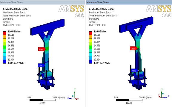
International Journal of Innovative Research in Science, Engineering and Technology (IJIRSET)

                        | e-ISSN: 2319-8753, p-ISSN: 2320-6710| www.ijirset.com | Impact Factor: 7.569|

                                        || Volume 10, Issue 7, July 2021 ||
                                         |DOI:10.15680/IJIRSET.2021.1007101|

i) Geometry Of Blade                                                  ii) Meshing

        Figure 4:-Modified Design Of Blade                                 Figure 5:-Modified Design Of Blade
             CAD Model (Geometry)                                                  CAD Model (meshing)

Meshing of blade assembly done. Mesh Type = Tetrahedral Mesh
Nodes=156118
Elements = 79115

iii)Boundary Condition
a) Fixed Support
  b) Force Applied(78780 N)

a) Fixed Support                                              b) Force

        Figure 6:-Modified Design Of Blade                                Figure 7:-Modified Design Of Blade
               CAD Model (fixed support)                                    CAD Model (force applied)

3.7. Finite Element Analysis
    A Linear Static analysis is performed, for finding displacement and stresses for different boundary conditions.In
FEM analysis there are three inputs geometry, meshing and boundary conditions in boundary condition we give the
data of loading, moment, after that it provide the results in the deformation, max shear stress , von- mises shear stress
by comparing all values we can find out about the result .

IJIRSET © 2021                                   |   An ISO 9001:2008 Certified Journal |                          9331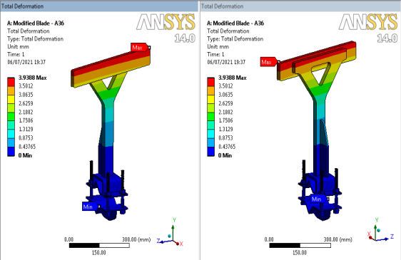
International Journal of Innovative Research in Science, Engineering and Technology (IJIRSET)
| e-ISSN: 2319-8753, p-ISSN: 2320-6710| www.ijirset.com | Impact Factor: 7.569|
|| Volume 10, Issue 7, July 2021 ||
|DOI:10.15680/IJIRSET.2021.1007101|
Material of blade is A36 Grade Steel
i)Material Properties ii)Total Deformation
Figure 8 : A36 Material properties table Figure 9: Total Deformation Developed
On Modified Blade
iii)Max Shear Stress iv)Von-Mises Stress
Figure10 : Maximum Shear stress developed Figure 11: Equivalent stress developed on Modified on Modified
blade. blade.
After applying different boundary conditions analysis is carried out. Maximum shear stress observed is 116.05 Mpa
which is lower than allowable stress . Thus blade design is safe.
Equivalent stress of blade is 228.7 MPa which is lower than allowable stress . Thus blade design is safe.
IV. RESULT DISCUSSION
As per the detailed study and observation from the existing concrete mixer blade assembly from Wainganga spun pipe
industry, modified blade is designed. it consist of selection material for blade, changes size & shape of blade &
designed modified blade.
In a modified blade assembly thickness of blade increases from 15 mm to 20 mm to sustain deformation of blade.
Which will results in increase strength of blade .Also width of modified blade is increased to its now mixes more
concrete uniformly .so there is no concrete remains between gap of two blades. Additional stiffener support gives to
the modified blade arm. So now it not break as it capable to withstand heavy shear stresses. Based on design
calculations graphical representation 3D CAD model of blade assembly and Modified model is generated in Creo 2.0
and to validate the design a finite element analysis is carried out in ANSYS . From the results it is observed that max
shear stress in blade assembly is found to be under allowable stresses and observed that the design is safe for the
given loading conditions.
IJIRSET © 2021 | An ISO 9001:2008 Certified Journal | 9332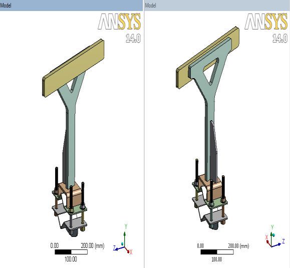
International Journal of Innovative Research in Science, Engineering and Technology (IJIRSET)

                        | e-ISSN: 2319-8753, p-ISSN: 2320-6710| www.ijirset.com | Impact Factor: 7.569|

                                         || Volume 10, Issue 7, July 2021 ||
                                           |DOI:10.15680/IJIRSET.2021.1007101|

                                              Total deformation(mm)             23.49
                      Existing Design =
                      A36 Steel Material      Max shear stress(Mpa)             365.14
                      (F=78780 N)
                                              von-mises stress(Mpa)             687.62

                         Modified Design      Total deformation(mm)             3.93
                         =
                         A36 Steel            Max shear stress(Mpa)             116.05
                         Material
                         (F=78780 N)          von-mises stress(Mpa)             228.73

        Table. 1: Result comparison Between Existing Design & Modified Design Of Blade with same material
                                                   & same force.

                                                     V.CONCLUSION

To increase the quality of concrete mixtures & machine efficiency we have design modified blade. The project includes
accumulation of data of concrete mixture machine, blade assembly , performing design calculations, modification in
existing model, cad modelling of proposed model is done. The performance of concrete mixer machine can be
improved by application of modified blade assembly. Finite element analysis of blade assembly is done. From the
results of finite element analysis, we can see the stresses developed in the design are within the allowable stress which
results in safe design. Modified blade of machine is safer & stronger to existing blade assembly and will become
useful in effective concrete mixture making. The existing blade design which has high max shear stress value , high
deformation value and high von misses stress value and low shear strength value the blade is found to fail. With the
study of the blade and using ansys software we found out the values and keeping with 6 cases we found o ut the best
blade assembly design the shear failure will be overcome. The cases which are consider in this project with the
calculations and stress analysis will help the other people to understand the design and analysis of blade assembly .

                                                     REFERENCES

[1]    Research Survey at- Wainganga Spun Pipe Industry Pvt. Ltd Sewagram Road , MIDC, Wardha.
[2]    Konstantin ,F.,“Regression model of the influence of the height of drum mixer blades on the quality of
       mixture” , E3S Web of Conferences ,175, 05047, 2020.
[3]    Zechen ,Y., “Mechanical Analysis And Optimal Design Of Mixing Paddlesforcsam Mixers”, Academic
       Journal Of Manufacturing Engineering, Vol.17, Issue 4, 2019 .
[4]    Zhang, Pan, F., Wuquan ,Y. , “Abrasive wear and optimal installation angle of concrete double‑horizontal
       shaft mixer stirring blades” , Springer Nature Switzerland AG 2020, Accepted, 15 April 2020 .
[5]    Khidir,T.,“Designing, Remodeling and Analyzing the Blades of Portable Concrete Mixture”, International
       Journal of Mechanical Engineering and Robotics Research , Vol. 7, No. 6, November 2018 .
[6]    Valigi ,M., “Twin-Shaft Mixers Mechanical Behavior Numerical Simulations of the Mix and Phases” ,
       machine article, Published, 2019.
[7]    Valigi,M., “Design of a new improved blade shape and 2D validation” , Elsevier, Tribology International 96 ,
       2016.
[8]    Ukwuaba,S.,“Design of a Low Cost Concrete Mixer Machine” ,American Journal of Engineering Research
       (AJER) ,Volume-7, Issue-5 , 2018.
[9]    Torotwa,I.,“A Study of the Mixing Performance of Different Impeller Designs in Stirred Vessels Using
       Computational Fluid Dynamics “, Designs , 2018.
[10]   Wankhede,A., “ Design Modification and Analysis of Concrete Mixer Machine” , IJRITCC, December 2015.
[11]   B.D. Shiwalkar, “ Design Data for Machine Elements”,Published by Denett & co. , ISBN 9778-81-89904-63-
       0., Revised Edition, 2011.
[12]   V. B. Bhandari Publisher , “ Design of Machine Elements Author”, TataMc Graw-Hill Education, ISBN
0070611416, 9780070611412,2007 .

IJIRSET © 2021                                   |    An ISO 9001:2008 Certified Journal |                         9333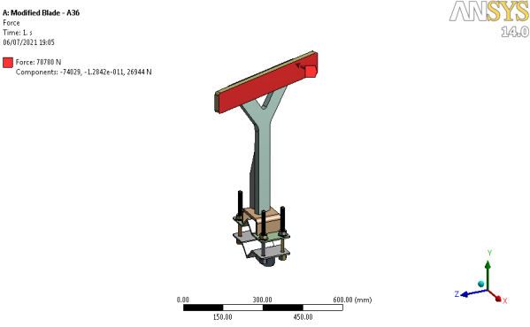
You can also read